
Abstract
To evaluate the reinforcement effectiveness of the grouted rock bolts, a dimensionless parameter’s approach (i.e. bolt density
Keywords
Introduction
Grouted rock bolts have been widely used in all civil engineering fields because of its simple structure, convenient construction, remarkable reinforcement effectiveness, low cost, and engineering adaptability, especially in cracked and softening rock masses. The grouted rock bolts can effectively improve the strength and stabilization of the surrounding rock through convergence control. 1 Although most researchers have contributed to the stress and displacement of tunnels and have solved many technical problems in practice, the effects of strain-softening characteristic on the stress and displacement of a tunnel, reinforced with grouted rock bolts, have yet to be defined clearly. And the method of ground reaction curve of circular tunnel excavated in strain-softening rock mass was initially proposed by Brown et al. 2 based on finite difference method.
The effects of the grouted rock bolts on rock mass have been studied by many researchers. Stille 3 and Stille et al. 4 presented a closed-form elastic–plastic solution of the grouted rock bolts. Five different approaches of bolt performance are considered in this model, and the results agree well with the measured data. Indraratna and Kaiser 5 developed an analytical model in which the elastic–plastic concept was adopted and a proper interaction mechanism between the ground and the grouted bolts was considered. Peila and Oreste 6 presented a new convergence–confinement approach able to model a reinforced rock mass zone surrounding an opening zone with new improved properties. Oreste and Peila 7 presented a new procedure for the computation of the convergence–confinement curves of a bolted tunnel. Fahimifar and Soroush 8 developed solutions for the stress and displacement of the tunnels that were excavated in softening rock mass and reinforced by the grouted rock bolts. Ranjbarnia et al. 9 proposed an analytical solution to determine the stress and displacement of a tunnel that was excavated in a brittle and strain-softening rock mass and reinforced with active grouted rock bolts. This solution is based on the nonlinear peak strength criterion. Osgoui and Oreste 10 developed an elastic–plastic analytical solution of an axisymmetrical problem for a circular tunnel reinforced by the grouted rock bolts. This improved model was based on the approach of Indraratna and Kaiser, 5 and the nonlinear Hoek–Brown (H–B) failure criterion was adopted. B Liu et al. 11 presented an analytical design method for the truss-bolt system in reinforcing underground fractured rock roofs in coal mines. Carranza-Torres 12 proposed the method of quantifying the mechanical contribution of rock bolts installed systematically around tunnels. Reinforcement of the effects of using rock bolt on rock mass with cross-flaws was explored by B Zhang et al. 13 X Li et al. 14 proposed an analytical model of shear behavior of a fully grouted cable bolt subjected to shearing to effectively evaluate the cable shear behavior and the influence of fully grouted cable bolts on joint shear resistance. A comprehensive study including laboratory tests and numerical modeling was performed to investigate factors of rock bolt fracture under varying loading conditions by H Kang et al. 15
In the analyses of engineering problems, the Mohr–Coulomb (M–C) and H–B failure criteria have been used widely by most scholars such as Carranza-Torres, 16 Park and Kim, 17 and Yang and Yin. 18 Lee and Pietruszczak 19 developed a numerical procedure for calculating the stress and radial displacements of a circular tunnel excavated in strain-softening rock mass, which obeyed the M–C and generalized H–B failure criteria. Park et al. 20 proposed the pressure-induced inflatable pipe method. The concept of cavity expansion for tunnel reinforcement was used. The interaction between tunnel supports and ground convergence was also investigated analytically and numerically in this approach. Zou and Li 21 proposed an improved numerical approach to analyze the stability of the strain-softening surrounding rock with the consideration of the hydraulic–mechanical coupling and the variation in elastic strain in the plastic region. In those literatures, the analytical and numerical solutions based on the plane strain assumption are discussed with different constitutive models (e.g. elastic–plastic model, elastic–brittle–plastic model, and strain-softening model) combined with the linear M–C or generalized H–B failure criteria. Although the solutions of the strain-softening surrounding rock based on M–C or H–B failure criterion are obtained by most researchers, the effect of the grouted rock bolts and the position of the neutral point was seldom considered.
The main objective of this article is to explore solutions for the stress and displacement of circular openings excavated in strain-softening surrounding rock. In the presented solutions, a numerical stepwise procedure that considers the reinforcement effectiveness and the neutral point of the grouted rock bolts is adopted and modified, where the deterioration of strength in the plastic region is considered. The improved model which considers the strain-softening behavior and is compatible with M–C and generalized H–B failure criteria was proposed based on model of Indraratna and Kaiser. 5
Theory and methodologies
Statement of the problem
As shown in Figure 1, in a continuous, homogeneous, isotropic, initially elastic rock mass, a circular opening with a radius (a) is excavated. The cross section of the tunnel is subjected to uniform hydrostatic pressure

Axisymmetric model and division of the zones around tunnel.
During excavation of tunnel, pin is gradually reduced. When the internal support pressure (pin) is less than a critical support pressure, plastic region will appear around the surrounding rock. After this initial yielding, the rock strength drops gradually following the post-yield softening behavior.
The strain-softening model is used, and the numerical stepwise procedure is improved for the solution for stress and strain in the plastic region.
The stress–strain relationship of the strain-softening rock mass is shown in Figure 2. Figure 2 displays the idealized relationships of

Strain-softening material behavior model.
Several assumptions below have been made to determine the solution of stress and displacement of the strain-softening surrounding rock incorporating the reinforcement effectiveness and the neutral point of the grouted rock bolts. The rock mass around the circular opening is regarded as an isotropic, continuous, and permeable medium which obeys the M–C or generalized H–B failure criteria under the plane strain condition. The strain-softening constitutive model that follows a non-associated flow rule is employed for formula derivation. The elastic strain in the plastic and softening regions of the surrounding rock obeys Hooke’s law.
Considering the reinforcement effectiveness and the neutral point of the grouted rock bolts, some assumptions are also needed.
Axisymmetric rock bolt patterns consisting of grouted rock bolts are installed with ST spacing around the circumference and with SL spacing along the longitudinal axis of the tunnel as shown in Figure 3.
The deformations between the rock mass and the grouted rock bolts are compatible.
The strength and deformation parameters deteriorate with the development of plastic deformation.

Fully reinforced circular tunnel.
Bolt density parameter and neutral point
As shown in Figure 3, a circular tunnel is reinforced by grouted rock bolts. The bolt density parameter proposed by Indraratna and Kaiser 5 is adopted to describe the global intensity parameter of the reinforced surrounding rock as follows

where
The number of the grouted rock bolts is presumably distributed uniformly on the tunnel surface in both the circumferential and longitudinal directions to maintain model symmetry. The horizontal distance between the two adjacent bolts, in the inner surface of the tunnel, is denoted by ST. The longitudinal space along the axis of the tunnel is represented by SL.
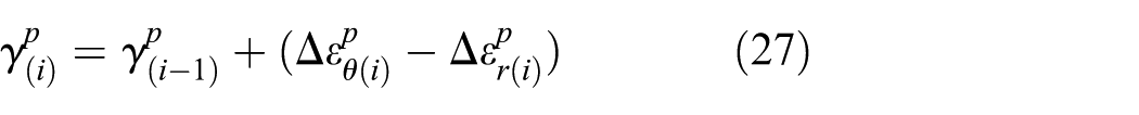
The shear stress is related to the first derivative of the axial stress. Hence, one point where the value of

The shear stress is characterized by the division of the rock bolts, a pick-up length and an anchor length, on either side of the neutral point. By the division of the rock bolts, pick-up side and anchor side, the shear stress is characterized as presented in Figure 4. The location of the neutral point is given by Indraratna and Kaiser 5


Stress distribution model for grouted rock bolts.
Three categories of the equivalent plastic zone
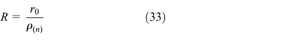
The plastic zone around the surrounding rock reinforced by the grouted rock bolts is redefined as the equivalent plastic zone. Because the location of the plastic zone is related to the neutral point and the bolt length, three cases (as shown in Figure 5) are analyzed and calculated for the determination of the equivalent plastic zone radius (R) and corresponding classifications are shown below.
Case I: minimal yielding:
Case II: major yielding:
Case III: excessive yielding:

Categorization of the yielding extent.
Failure criterion
The M–C failure criterion is given by

where
The following generalized H–B failure criterion is adopted by
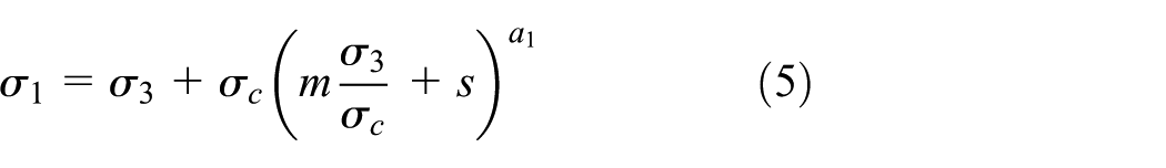
where
The strength and deformation parameters of the strain-softening rock mass are evaluated based on plastic deformation and are controlled by the plastic deviatoric strain19,22

where
The bilinear function that adopts the plastic shear strain to describe the physical parameters of the surrounding rock mass19,22 is presented by

where
Stress and strain solutions based on the M–C failure criterion
Stress and strain solutions in elastic region
The solutions of stress, strain, and displacement in the elastic zone considering the reinforced rock are given by Indraratna and Kaiser 5 as follows


The relationship of the radial stress and the tangential stress at the interface between the elastic rock and the equivalent plastic zone is presented by

Combining equations (4) and (11) leads to

where
Stress and strain solutions of excessive yielding
Zone I:
In zone I, the plastic zone is beyond the reinforced zone. The stress equilibrium equation of an element near an unsupported opening can be represented by

In a bolted element, as shown in Figure 6, the stress equilibrium equation is given by
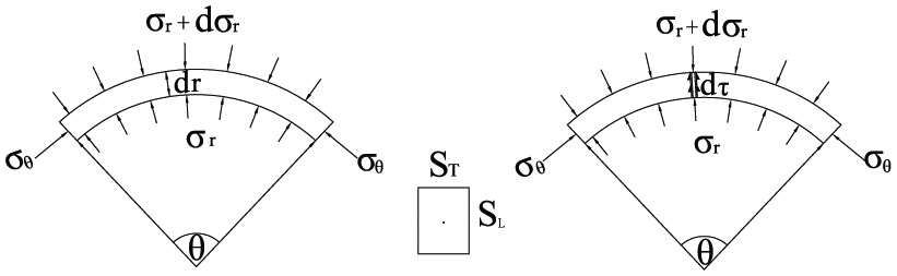
Equilibrium considerations for bolt–ground interaction.
Equations (13) and (14) describe the stress equilibrium condition of the unreinforced and reinforced segments, respectively. If the terms

where
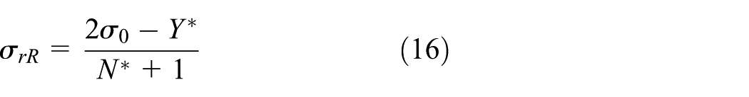
If the bolt density parameter is introduced into the stress equilibrium equation, the radial stress at the interface between the elastic rock and the equivalent plastic zone can be modified by
Considering the reinforcement effectiveness of the grouted rock bolts, the residual strength parameters of rock mass can be represented by
The total plastic region is presumably divided into n connect annuli which are bounded by two annuli of the radius

Normalized plastic region with the finite number annuli.
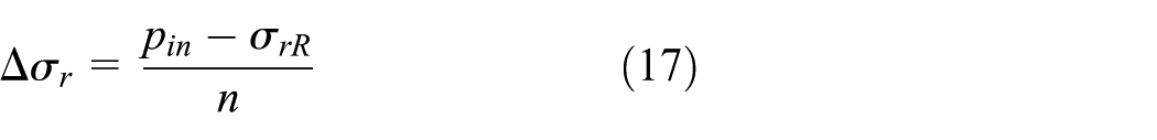
So the radial stress components for ith radius can be

For a large magnitude n, the corresponding tangential stress is given by

where
So the tangential stress components can be represented by

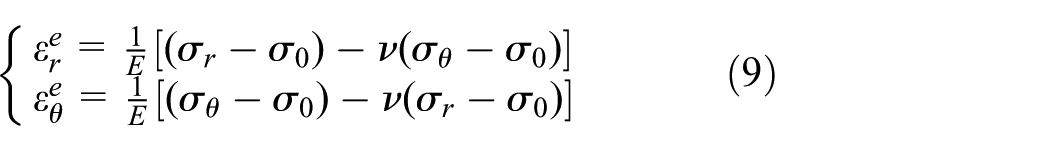
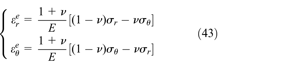
Under the plane strain condition, the elastic strain increments can be obtained using Hooke’s law as follows

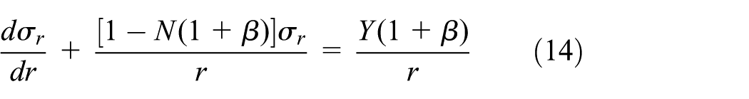
The stress equilibrium differential equation that considers the reinforcement effectiveness of the grout rock bolts for the ith annulus is derived using equation (15) and expressed as equation (22)

where
The normalized inner radius

where
The compatibility equation can be written in the general form as follows
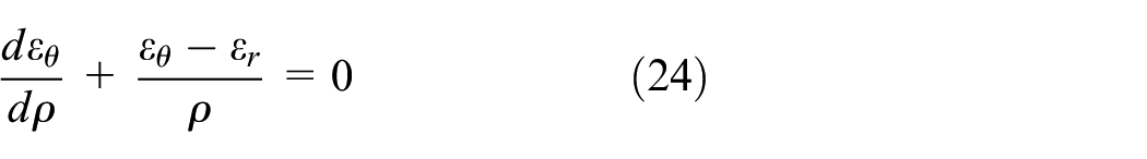
where
The total strain in the plastic zone that is the sum of the elastic strain and the plastic strain is given by

Combining equations (22) and (23) leads to
where
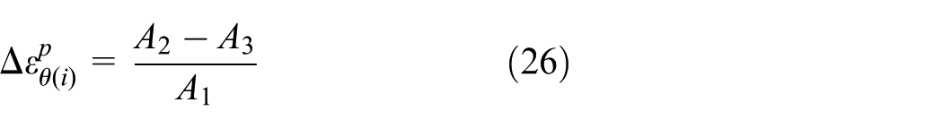
Using equation (6), the plastic deviatoric plastic strain can be expressed by
So the total strain at ith ring is given by

Through the relationship between strain and displacement, the displacement at ith annulus can be obtained as

Thus, the stress and displacement solutions of the reinforced rock in this plastic region are obtained.
Zone II:
This is the middle plastic zone which is confined between the neutral point and the bolt end. Consequently, the rock mass is subjected to the negative shear stress of the rock bolts. So the rock mass has weak values of the strength parameters as follows

If
The first annulus in zone II is the interface between the plastic zones I and II, and the boundary conditions of stress and strain in this region can be obtained. Then as with zone I the stress and strain can be calculated by stepwise method.
Zone III:
This yielded zone is confined by a range between the tunnel boundary and the neutral point. It falls within the pick-up length of the rock bolts and is stabilized by the positive shear stress. The residual plastic zone is reinforced and its strength parameters are effectively increased, and the strength parameters maintain the residual strength as follows

The boundary condition of the stress and strain in region II is used as the initial condition of region III. Then the calculation steps are the same as region II.
Since

The procedure explained above can be repeated for n times until
Stress and strain solutions of major yielding
Zone I:
Zone I is in elastic state and beyond the rock bolts. The stresses in elastic zone are given by

where
Zone II:
This is the inner elastic zone within the reinforced zone. The stress in this zone is given by

Zone III:
This is the outer plastic zone beyond the neutral point. The strength parameters of rock mass begin to decrease from maximum values
The stress and strain of rock mass are solved by the same method explained in section “Stress and strain solutions of excessive yielding
Zone IV:
This yielded zone is confined between the neutral point and tunnel boundary, and the same approach in section “Stress and strain solutions of excessive yielding
Stress and strain solutions of minimal yielding
Zone I:
This is the outermost elastic zone, and the stress is given by

where
Zone II:
The anchor length of the rock bolts is contained in this elastic zone. The stress can be represented by

Zone III:
This elastic zone is confined to the end of the pick-up length of the rock bolts. The stress is given by
Zone IV:
This region is the plastic zone. The stress and strain of rock mass are solved by the same method explained in section “Stress and strain solutions of excessive yielding
Stress and strain solutions based on the H–B failure criterion
Stress and strain solutions in elastic region
Taking excessive yielding

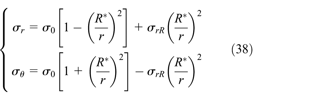
The relationships of the radial and tangential stresses at the interface between the elastic rock and the equivalent plastic zone are presented by

Considering the reinforcement effectiveness of the grouted rock bolts, the radial stress at the interface between the elastic rock and the equivalent plastic zone can be modified as follows
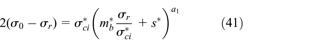
Equation (41) cannot be solved linearly, and the value of
The stress, strain, and displacement in the elastic zone are represented as follows, respectively


Stress and strain solutions in plastic region
Similar to the solutions based on the M–C failure criterion mentioned in section “Stress and strain solutions of excessive yielding
The stress equilibrium differential equation that considers rock bolts’ effectiveness for the ith annulus is expressed as equation (45)

where
The normalized inner radius

The increment of the tangential strain is represented by

where
The displacement at each ring can be obtained using the relationship between the strain and displacement.
We can use the same method in section “Stress and strain solutions in plastic region” to calculate the stress and displacements of another two categories: the major yielding
Validations
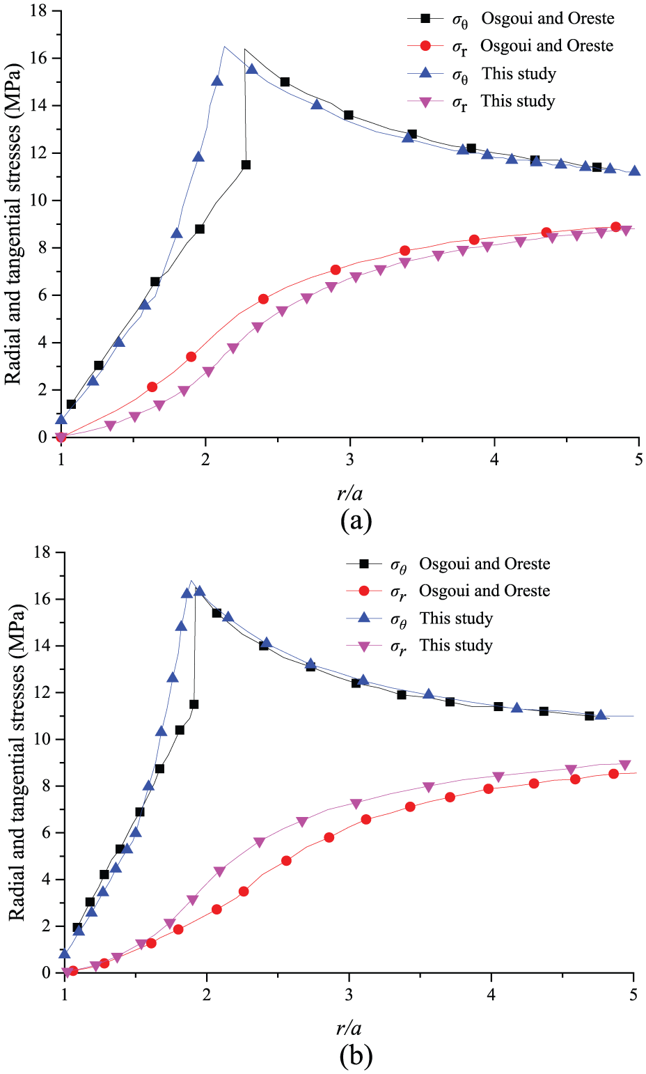
To validate the accuracy of the proposed approach based on the M–C and the generalized H–B failure criteria, the results of the proposed approach for

Stress curve comparison for different
The results of the proposed solution based on the generalized H–B failure criterion incorporating the neutral point of the grouted rock bolts for the cases of β = 0 and β = 0.132 based on the generalized H–B failure criterion are also compared, respectively, corresponding to a = 2.0 m, E = 5.7 GPa, ν = 0.3, σ0 = 10 MPa,
As is demonstrated in Figure 8, for the cases of
Numerical analysis and discussion
Comparison with elastic–brittle–plastic model
To study the effect of strain-softening in combination with the grouted rock bolts on the stress and displacement, the stress and strain curves are plotted to compare the strain-softening model with the elastic–brittle–plastic model proposed by Indraratna and Kaiser 5 and Osgoui and Oreste, 10 respectively.
Figures 9–11 depict the differences between the predicted results of the strain-softening model and elastic–brittle–plastic model with different bolt densities. It is shown from Figures 9 and 11 that stresses presented by the proposed model are larger than those based on the elastic–brittle–plastic model at the same point in the tunnel. Moreover, as is shown in Figures 14 and 15, the plastic radius of the proposed model would be reduced by 10% and 12%, respectively, for β = 0.145 and 0.291. The probable reason is that the strength parameters of strain-softening model are larger than those of the elastic–brittle–plastic model in some annuli of the plastic zone. As can be seen from Figure 9(c) that with the increase in the bolt densities, the stress curves of the proposed model are more agreeable with the curves based on the ideal elastic–plastic model in comparison with the elastic–brittle–plastic model.

Stress comparison for different β: (a) β = 0 and γp = 0.008, (b) β = 0.145 and γp = 0.008, and (c) β = 0.291 and γp = 0.008.

Strain curve comparison for different β: (a) β = 0 and γp = 0.008, (b) β = 0.145 and γp = 0.008, and (c) β = 0.291 and γp = 0.008.
Stress curve comparison for different γp: (a) β = 0 and γp = 0.047 and (b) β = 0.132 and γp = 0.047.
It can be found from Figure 10(a) and (b) that the tangential strains presented by the proposed model are smaller than those presented by Indraratna and Kaiser 5 at the same point. Moreover, as shown in Figure 10(c), when the bolt densities increase, the results are closer to those based on the ideal elastic model in contrast to the elastic–brittle–plastic model.
It can be noted that the displacement in Figure 12 presented by the proposed model is smaller than those presented by Osgoui and Oreste.
10
For example, the radial displacement decreases from 18.2 to 15.3 mm if

Radial displacements’ curve comparison.
Effects of the bolt density parameters
Figure 10(b) illustrates that the stress grows with the increasing bolt densities at the same point. The plastic radius would drop correspondingly for a larger
Several examples are conducted to highlight the effects of bolt density parameters that incorporate the neutral point of the grouted rock bolts on stress and strain.
To examine the effects of bolt density parameters under M–C failure criterion, three cases are performed: (1) β = 0, γp = 0.008; (2) β = 0.145, γp = 0.008; and (3) β = 0.291, γp = 0.008. The input data are the same as those listed in section “Validations.”
The results are displayed in Figures 13.

Results for different
For several given bolt densities, the radial displacements with different hydrostatic pressures and internal support pressures are shown in Figure 14(a) and (b). The tendency that the displacement of the reinforced surrounding rock decreases with the
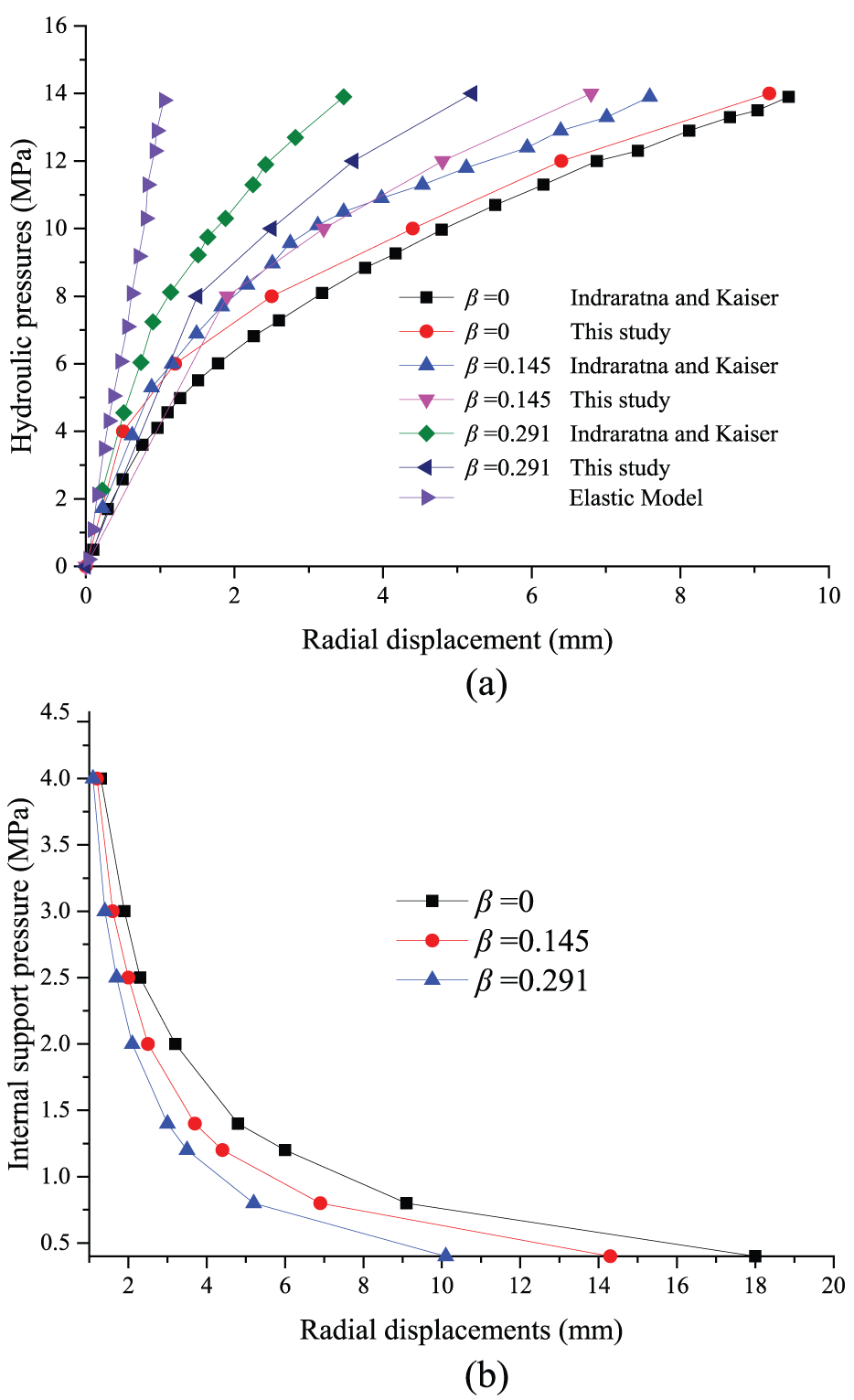
Radial displacement of tunnel under (a) different hydraulic pressures and (b) different internal support pressures.
Based on the H–B failure criterion, two cases are carried out corresponding to (1) β = 0 and γp = 0.0047 and (2) β = 0.132 and γp = 0.0047 to examine the effects of the bolt density parameters. The input data are listed in section “Validations.”
The results are displayed in Figure 15(a)–(c).

Results for different
It can be seen from Figure 15(a) that stress increases with the increasing bolt densities at the same point. The plastic radius would be reduced correspondingly for a larger
As shown in Figure 15(d), the radial displacement in the tunnel wall decreases when the increasing internal support pressure increases. The displacement of the reinforced surrounding rock corresponding to a larger
Effects of the strain-softening parameters
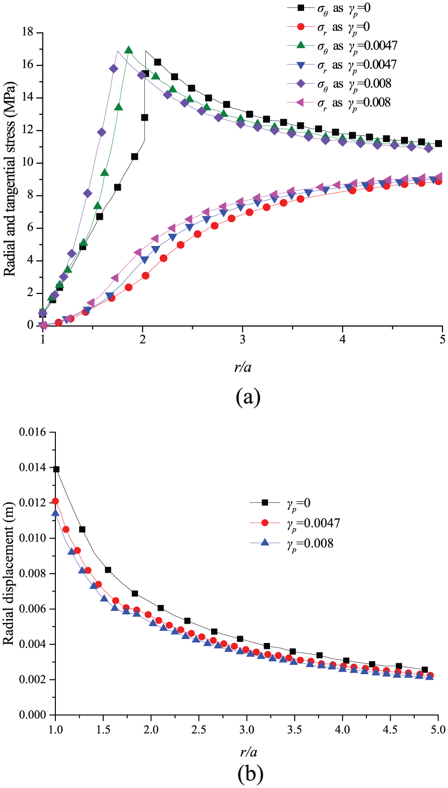
To identify the effect of
It can be seen from Figures 16(a) and 17(a) that the stress increases with the increase in

Result for different
Comparison for different
Hence, it would be easy to note that
The effects of
Comparison with in situ monitoring data
General situation of engineering
Sanchahe Tunnel is located in the slope transition zone between Yunnan Guizhou Plateau and Guangxi hilly. The pile number of the left tunnel of Sanchahe Tunnel is ZK74 + 277–ZK75 + 245, the surrounding rock of the tunnel is mainly the plastic gravel containing silty clay, the length is 968 m, and the maximum buried depth is about 91.3. The zone ZK74 + 277–ZK75 + 615 is the key monitoring object; because the surrounding rock is soft and the stability is pretty poor, the surrounding rock properties are poor, such as joint and fissure, rock mass fragmentation, and the shape of the loose soil. The vertical section profile of ZK74 + 277–ZK75 + 615 is shown in Figure 18.

The vertical section profile of Sanchahe Tunnel: (a) the vertical section profile of Sanchahe Tunnel at ZK74+277-ZK74+895 and (b) the vertical section profile of Sanchahe Tunnelat ZK74+895-ZK75+275.
Measurement of radial displacement
The ground deformation of this tunnel is monitored and measured by multi-point borehole extensometers. Multi-point borehole extensometers are installed within the tunnel ground and they measure the displacement of the tunnel wall relative to the fixed end-point of each borehole extensometer along the direction of radius (Figure 19(a)).

The in situ monitor site: (a) installation of multi-point borehole extensometers and (b) arrangement of measuring points.
The scheme of radial displacement measurement is presented as follows:
First, determination of the location and depth of drilling; next, drilling and instrument installation; finally, grouting and sealing.
The measurement section locates in a representative geological section; we chose ZK74 +290, where the surrounding rock is soft and the stability is pretty poor.
To facilitate the calculation and analysis, each measurement section should be laid on eight multi-point borehole extensometers around the tunnel wall; each borehole extensometer could measure six points along the radius. And the arrangements of multi-point borehole extensometers should be close to the anchor.
The measurement frequency is once a day.
Calculate the radial displacements of six points along the radius by averaging the measured data of eight multi-point borehole extensometers.
Result analyses
Based on geological investigation report, the recommended parameters of rock mass are shown as follows: a = 5.6 m, L = 3.8 m, E = 1500 MPa, ν = 0.35, σ0 = 15 MPa, σC = 3.5 MPa, Pin = 1.5 MPa, γp = 0.008, mp = 2.0, ap = 0.50, sp = 0.0045, mr = 1.0, ar = 0.55, and sr = 0.0025; these are estimated approximately. In order to verify the accuracy of the model, we collected the monitoring data about the relationship between the radial displacement and the radius.
Based on the M–C failure criterion, the results of the improved model that considering the bolt density
Based on the generalized H–B failure criterion, for the relationships between the radial displacements and the radius for the case of

Comparison based on M–C failure criterion.
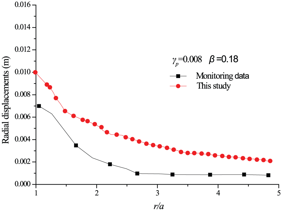
Comparison under generalized (H–B) failure criterion.
Conclusion
Incorporating the strain-softening characteristic of the surrounding rock and the neutral point of the grouted rock bolts, the equivalent plastic zone is divided into three categories (i.e. minimal yielding, major yielding, and excessive yielding). The potential plastic zone is sufficiently subdivided into a large number of concentric annuli; the bolt density parameters are introduced, the solutions of stress and displacement of circular tunnel are presented, and the corresponding calculation approach is proposed as well. Based on the elastic–brittle–plastic model, the proposed model is validated by the special case as
In practical tunnel engineering, the proposed approach can be widely used to evaluate the reinforcement effectiveness due to its simple practicality. In our future work, we will compare our results to in situ monitoring data. Furthermore, the model can be extended to a similar problem in other projects, such as slope engineering, foundation pit engineering, and mining engineering.
Footnotes
Appendix 1
Academic Editor: Jose Ramon Serrano
Declaration of conflicting interests
The author(s) declared no potential conflicts of interest with respect to the research, authorship, and/or publication of this article.
Funding
The author(s) disclosed receipt of the following financial support for the research, authorship, and/or publication of this article: The authors are grateful to the 973 Program (2013CB036004) and National Natural Science Foundation of China (no. 51208523).