
Abstract
Improving control quality in inverter systems has attracted considerable attention, particularly in multilevel inverters for high-power applications. This study suggests a straightforward predictive direct power control system for a five-level Active Neutral Point Clamped inverter connected to the grid. The proposed method offers the benefit of reducing the heavy computational load by implementing a two-stage optimization process for the objective function. In contrast to the conventional finite control set model predictive control which involves comprehensive searches for all possible switching configurations within the iterative optimization process, the suggested approach focuses only on potential voltage vectors based on the desired inverter voltage’s location at the initial stage. Second, the self-balancing flying capacitor voltages are guaranteed by employing the duplicative switching states. Another advantage of the presented algorithm is an obviation of numerous selecting weighting factors. The effectiveness of the advanced strategy is confirmed through extensive comparative simulation and hardware-in-the-loop studies conducted in both conditions during stable states and transitions. Contrasted to the previous technique, this innovative method demonstrates an improvement in the grid’s power ripple and total harmonic distortion of the current by 14.66% and 19.58%. Furthermore, the computational time required for this method is significantly reduced by 64.58%, and 61.36% correlate to the traditional and other approaches, respectively. These results may facilitate the implementation of an effective control approach for multilevel inverters, employing a cost-effective control platform by a limited sampling interval.
Keywords
Introduction
Multilevel inverters (MLIs) have become a subject of considerable fascination in high-power medium-voltage applications because of their ability to minimize voltage stresses, maintain base
Traditional control techniques are commonly employed in power electronic applications, but they have drawbacks related to handling nonlinearities and constraints, parameter tuning, and low transient response. 8 Addressing multi-objective issues using traditional techniques like linear control techniques with modulation methods involving pulse widths or spatial vectors is considered difficult. For instance, in APNC inverters, the task involves not only regulating the output current but also concurrently accomplishing a balance of FC voltages and DC-link capacitor voltages (Figure 2).9–11 Several improved control methods have lately been implemented for multilevel inverters. Among these approaches, model predictive control (MPC) stands out as a promising strategy. There are two types of MPC: continuous control set MPC (CCS-MPC) and finite control set MPC (FCS-MPC). The CCS-MPC involves calculating the desired vector and using a modulation technique to produce switching signals. However, its notable drawback lies in the high computational burden, particularly when constraints and nonlinearities must be considered. On the contrary, FCS-MPC leverages the finite compact set of the inverter’s switch status to specify the best one by minimizing the objective function. The FCS-MPC offers particular advantages, including rapid dynamic response, simplicity, and the capacity to manage numerous control goals and restrictions.12,13 In terms of real-time computations, one of the key obstacle faced by FCS-MPC is the significant computational burden for MLIs due to the comprehensive exploration of all the combinations of switching control gates in an online computational phase, particularly for MLIs at higher levels. This leads to extended execution times, necessitating prolonged control cycles and negatively impacting control performance. The employment of a digital processor with fast computational capabilities is one possibility, but it comes at the cost of increased system prices. The decrease in computational cost of the FCS-MPC has garnered significant interest and continues to be the subject of ongoing investigation.
Unlike two-level inverters, the 5L-ANPC inverter requires the assessment of 512 voltage vectors at every sampling interval, resulting in a heightened computational challenge. Zhang et al.
14
and Zhou et al.
15
introduce a new methodology for the implementation of three-level NPC inverters. The initial step involved the computation of the voltage vector reference, which was then directly compared with the existing voltage vectors to assess the objective function. These approaches led to a considerable decrease in the iteration period required for predicting control objectives associated with voltage vectors, as well as a lowered computational load. Nevertheless, applying these methods to high-level MLIs, particularly those with a significant quantity of duplicative switching status, poses challenges. The evaluation of numerous redundant switching states necessitates extensive calculations, making the application of these methods less straightforward in such cases. A recent MPC technique was introduced in Sun et al.
16
to decrease the number of computations needed for three-level ANPC-fed PMSM. This method involves the calculation of the predictive voltage sign which is incorporated with the switching conditions of a half-bridge module to create a novel set of viable voltage vectors through a hysteresis technique. Nevertheless, this approach doesn’t consider the balance of the FC voltage which is required for the 5L-ANPC inverters. MPC methods implicating numerous vectors17,18 utilize two or three active voltage vectors in each sampling time instead of just one. While these techniques were initially designed for two-level inverters, they cannot be directly adapted for multilevel inverters. MLIs present challenges for direct application primarily thanks to their substantial number of redundant switching states. The selection process for two or three voltage vectors from this pool causes complex calculations. Applying the FCS-MPC with model approximation
19
in the context of the 5L-ANPC reduces the assessed converter states from 512 to 24. However, this reduction in computation results in a decrease in control performance compared with the classic FCS-MPC, leading to inferior tracking accuracy and increased voltage ripples in the FC and DC-bus. The underlying cause of this degradation is the omission of redundancies inherent in the three-phase converter by the system model approximation. An alternative technique
20
is recommended for the one-phase split-capacitor ANPC inverter to circumvent the requirement of forecasting the mid-point voltage of the DC-bus in the objective function. This is achieved by incorporating the balance of the DC-bus directly into the control goal of FC. This approach fails to incorporate the power control of the grid-connected inverter.
21
introduced a method to restrict the level jumps of inverter voltage, which reduces the number of switching states and shortens computation time. However, this strategy may adversely affect control performance by omitting several switching states. Within the framework of Yang et al.22,23 and Liu et al.,
11
a MPC strategy is presented for a 5L-ANPC converter, utilizing a constant switching frequency and employing two or three vectors during each control duration. The initial phase identifies the timing for applying vectors through the analysis of the objective function, whereas the second phase incorporates the concept of the current gradient. However, these approaches require calculating duration times for optimal sequences, resulting in the heightened intricacy of the control strategy.
24
improved a control methodology by incorporating sector distribution into the FCS-MPC for four-level nested NPC inverters. Nonetheless, the approach remains somewhat cumbersome due to the differing effects of the redundant switching vector on the balance of FC voltages, which limits the practicality of implementing the algorithm with a brief sampling interval. Wu and Wang
25
presented a new approach for controlling the current of four-level T-type NPC inverters with
Effectively managing various objectives stands out as a primary advantage of FCS-MPC. Nonetheless, the process of coordinating multiple weighting coefficients to attain satisfactory performance across all objectives is complex and burdensome. Incorporating topology-related objectives is vital for ensuring the proper operation of MLIs, which largely depends on the inverter’s configuration. An illustrative example is the necessity for balancing the FC voltage and the neutral point voltage of the DC bus, a critical purpose for 5L-ANPC inverters. The recommendations outlined by Harbi et al. 13 focus on the empirical determination of suitable weighting factors, employing a heuristic algorithm in the process. Alternative approaches involve optimizing a cost function with an artificial neural network, 26 utilizing a normalized weighted sum model, 27 employing an auto-tuning procedure for dynamically choosing weighting elements in real time based on fuzzy logic, 28 and implementing multiobjective optimization using decision-making multiple criteria. 29 However, these approaches elevate the computational load and add complexity to the control process of FCS-MPC. Several methods are suggested to eliminate the impact of coefficient factors on the cost function. A hybrid MPC is presented in Dehong et al. 30 for 5L-ANPC converters. This method ensures control objectives by separating the low-frequency and high-frequency components of the converters. However, it necessitates determining the optimal duty cycle for tracking current and modulating control switching signals. In Xiao et al., 31 a novel cascaded MPC is introduced for induction motor drives that are powered by a 3L-ANPC inverter. This framework sequentially assesses the flux vector and neutral point voltage. While it is feasible to eliminate the weighting factors, this technique demands a higher level of calculation to identify the optimal solution.
Inspired by the issues outlined earlier and the prior efforts to handle the limitations of traditional FCS-MPC and the previous techniques, our study introduces a straightforward predictive direct power control scheme for a grid-connected 5L-ANPC inverter with flying capacitor voltage self-balancing. A predictive model is employed to estimate the grid current and the neutral point voltage of the DC bus. The control variables are derived from the anticipated state variables of the system alongside the observed measurements. Control objectives, such as the regulating of grid power, the equilibrium of FC voltages, and the stabilization of neutral point voltage, are realized through the established cost function via three stages. In the first stage, the suggested approach identifies the desired inverter voltage’s location based on the predictive powers, their reference, and grid voltage. The viable voltage vectors of 5L-ANPC inverters for the optimization loop are reduced from 125 to 35 during the second stage. At the final stage, the inverter achieves its optimal switching state by combining the most effective inverter voltage from the minimization loop with the appropriate redundant switching states for FC voltage balancing. The primary advancements highlighted in this article include:
The offered strategy notably decreases the computational load by about 91% compared to the traditional FCS-MPC.
13
This reduction is achieved through the elimination of the computational load needed for predicting FC voltage and, additionally, by decreasing the number of predictions for grid current and neutral-point voltage, along with the evaluations of the cost function. Contrasted to the previous method,
25
the mean computation time of the proposed approach is reduced by 56.4% from 39
The proposed technique balances the FC voltages by utilizing a straightforward logic state to choose the appropriate combination control gate among the redundant switching vectors. Three control goals of the system only use one weighting element, simplifying control intricacy by eradicating the burdensome task of coordinating multiple weighting factors.
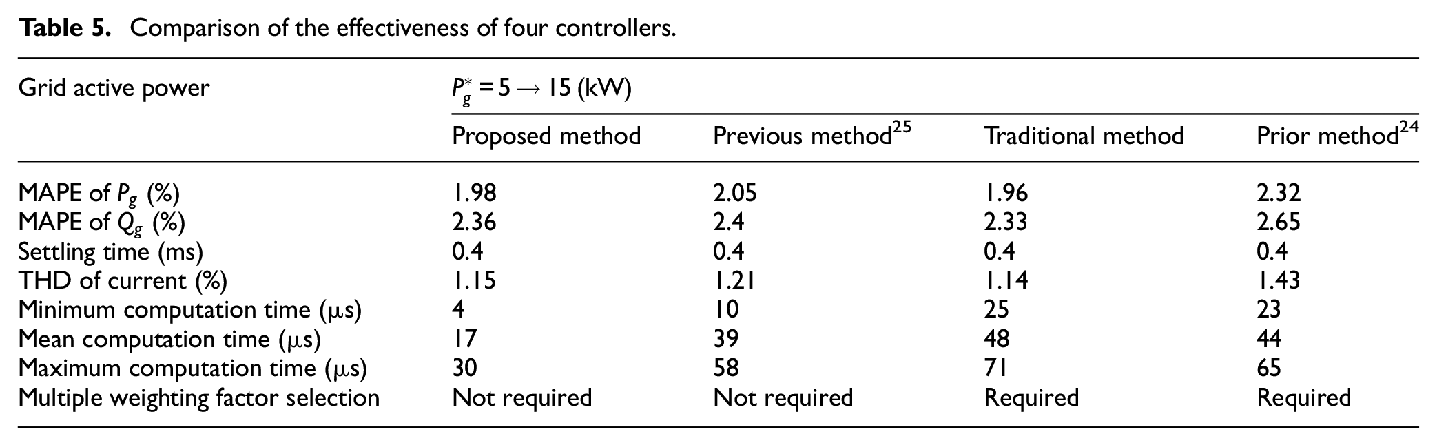
The offered approach performs as well as traditional FCS-MPC in both dynamic and steady-state operations, including time taken for stabilization, power fluctuations, and total harmonic distortion (THD) of the current, while extremely decreasing computational cost. The algorithm put forth an improvement in steady-state performance compared to the other methods,24,25 primarily due to its successful mitigation of the issues related to the selection of multiple optimal weighting factors. The mean absolute percentage error of power ripples is diminished by 3.41% and 14.66% compared to the previous method 25 and prior technique, 24 respectively. The proposed strategy resulted in a THD of 1.15% in the grid current, contrasting with the 1.28% found in the technique mentioned in Wu and Wang 25 and the 1.43% recorded for an alternative approach. 24
The format of this paper is as follows: Section “Description and modelling of the grid-tie five level ANPC inverter” outlines the 5L-ANPC configuration and the mathematical model. The details of the suggested straightforward FCS-MPC strategy are provided in Section “Direct power control with simplified self-balancing of the flying capacitor voltage approach based on the FCS-MPC scheme.” Section “Simulation and processor-in-loop results” includes simulation verification, comparison analysis, and results discussion. In conclusion, Section “Conclusions” summarizes the paper.
Description and modelling of the grid-tie five level ANPC inverter
The reduced configuration of the grid-tie five-level ANPC inverter is illustrated as Figure 1.10,23 Every stage of the inverter is made up of eight power switches and one FC. The switches for each phase work in a way that complements each other, such as (
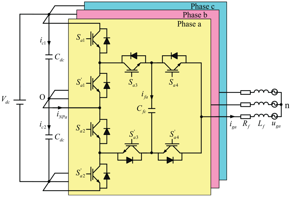
Structure of the grid-connected 5L-ANPC inverters.
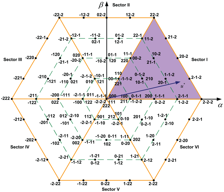
Voltage vector sector distribution provided by the 5L-ANPC inverter.
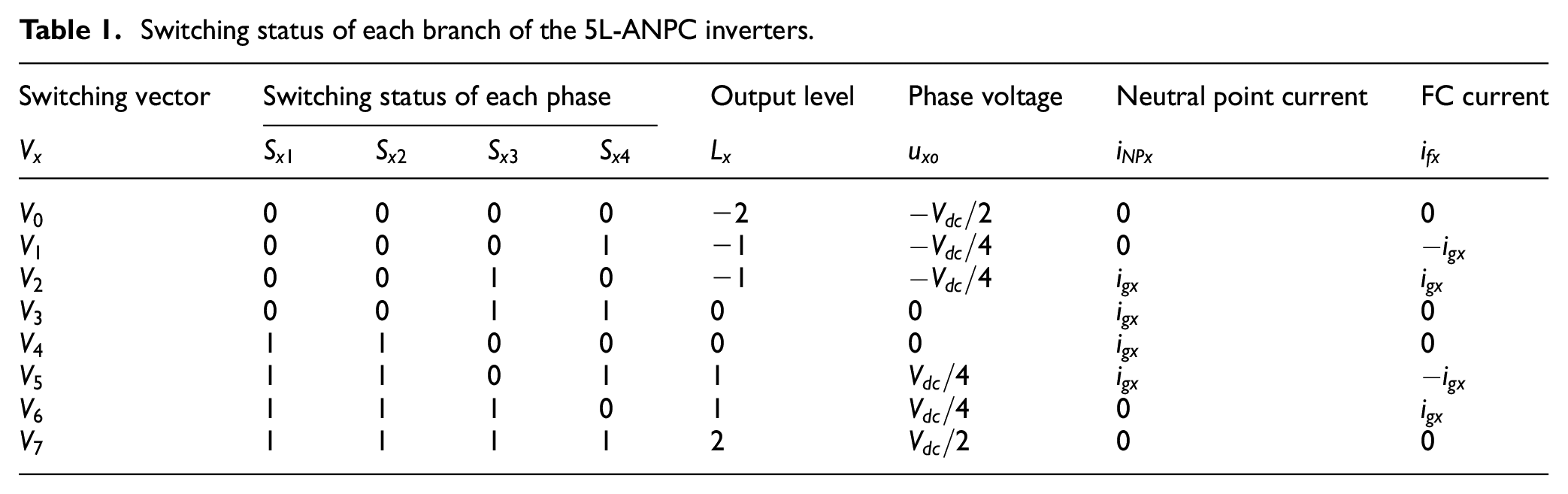
Switching status of each branch of the 5L-ANPC inverters.
The dynamic model of the grid-connected 5L-ANPC inverters is simplified under the assumption of symmetrical three-phase grid voltage and constant DC-bus voltage.
The inverter’s output phase voltage concerning neutral-point

where
The voltage equations that depict the dynamic behavior of each phase are stated as follows11,21:
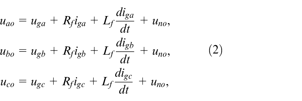
where the filter resistance and inductance are indicated by
Supposing the output three-phase voltage is symmetrical, the reduced dynamic model of the inverter-connected grid can be derived as21,25:

where
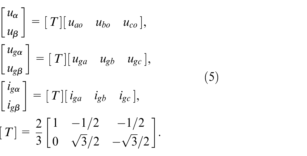
Referring to (3), the continuous-time presentation of the current can be rewritten as a stationary frame:

where
With the assumption of constant DC-bus voltage, the mathematical model of the capacitor voltage is expressed as 13 :
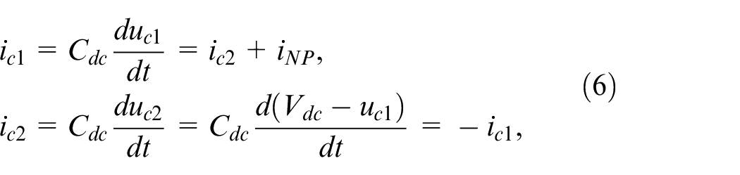
where

The behavior of voltage oscillation in a flying capacitor can be expressed as:

where

Employing forward-Euler discretization method to the dynamic model of a system described in (4), (6), (7), and (8), the discrete-time presentation is given by12,13:
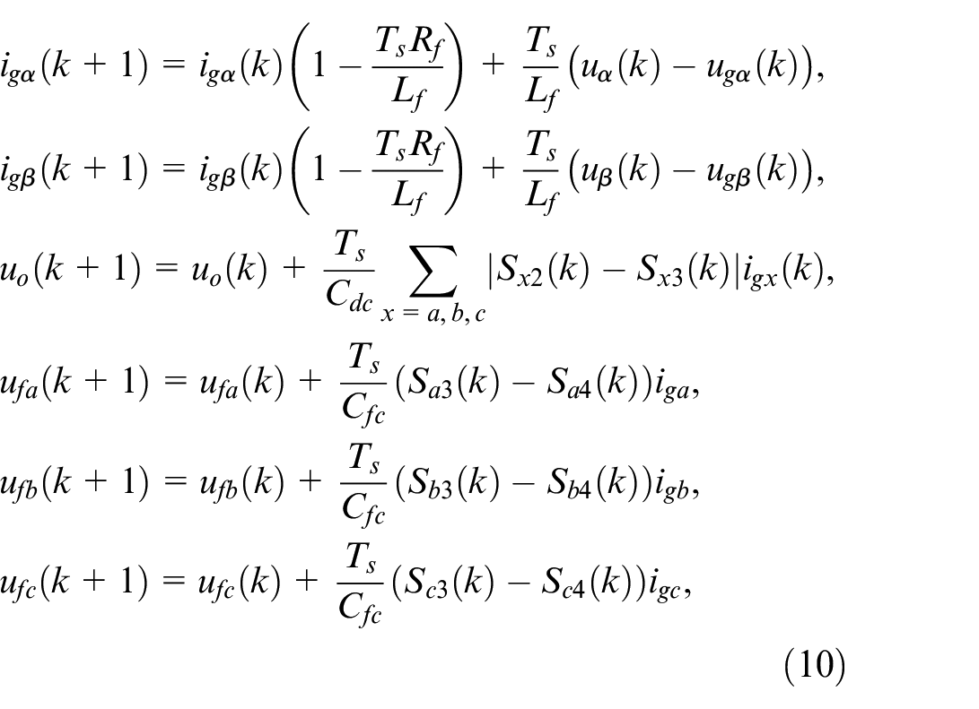
where
The active and reactive power can be determined the components of the grid voltage and current 24 :

Direct power control with simplified self-balancing of the flying capacitor voltage approach based on the FCS-MPC scheme
The main goals of the control strategy are:
Monitor and regulate the desired levels of active and reactive power in the grid.
Keep equilibrium of the DC-bus capacitor voltage.
Balance the voltage of the FC.
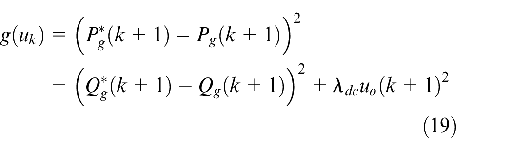
To accomplish these aims, the traditional FCS-MPC utilizes an appropriate cost function, given by12,13:
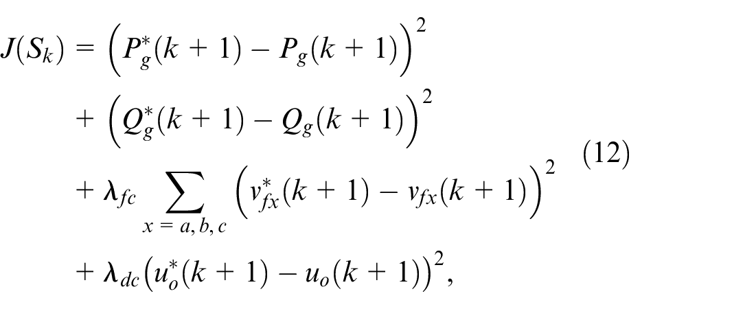
where
The expected future grid power transfer values are derived using the Lagrange extrapolation method 12 :
The control switching inputs refer to the different combinations of operational statuses, which consist of three subsets:

Table 1 shows that the voltages of FC are significantly influenced by two redundant combinations of switches (
Facilitated logic condition for determining the proper switching vector of balancing FC voltage.
If we disregard the resistance of the filter, equation (4) can be rephrased in the
Assuming that the grid voltage remains steady because of a brief sampling term
The purpose of our approach is to follow the reference value of grid power. Therefore, it can be inferred:
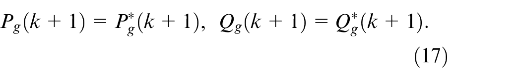
The desired inverter voltage is obtained by substituting (15) and (17) into (16):
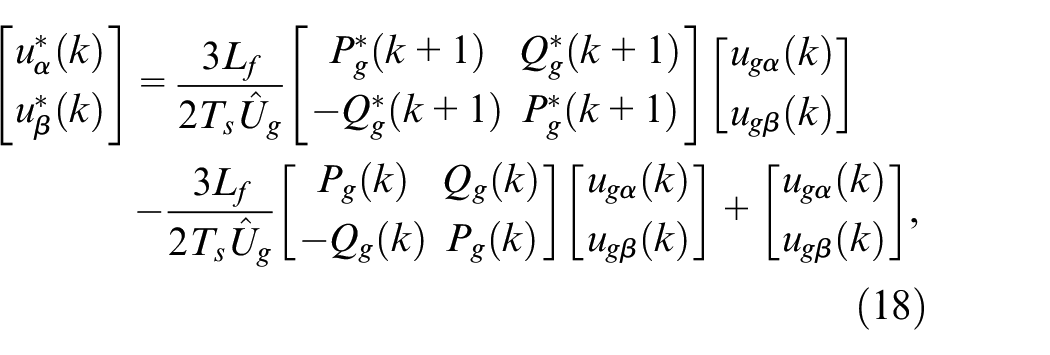
where
The typical FCS-MPC method utilizes 512 potential control inputs from the 5L-ANPC inverters to optimize the control objective and achieve the best combination sequence of the switches Consequently, this approach results in a significant computational workload, necessitating either a robust processor or an extended sampling time. Unfortunately, longer sampling times can negatively impact the performance of the control system. Various approaches have been suggested to alleviate the computational load associated with multilevel inverters.
21
suggested the level jump limitation technique of inverter voltage to minimize the number of switching states, leading to a decrease in computation time. However, the control performance deteriorates due to eliminating several switching states. In addition, the choice of numerous weighting elements is the drawback of this technique.
24
enhanced a control technique by integrating sector distribution into the FCS-MPC for four-level nested NPC inverters. Nevertheless, it is still a bit extensive because of the varying influence of the duplicative switching vector on the equilibrium of FC voltages. This leads to the unfeasibility of executing the algorithm with a short sampling interval. To solve the problems above, our research paper introduces a proposed method that not only effectively tackles the heavy computational burden but also ensures the FC voltage self-balancing without the need for a weighting factor. The control approach comprises a three-phase strategy. During the initial phase, the needed inverter voltage’s sector position is determined by utilizing predictive power and its reference in conjunction with grid voltage. In this case, we can select the inverter voltage vector from sector I to VI. For example, there are 35 feasible inverter voltage vectors of sector I as indicated by Table 3. However, the 5L-ANPC inverter has 150 possible switching states due to the different impact of the FC voltage and neutral-point voltage. Moreover, two redundant vectors,
Possible switching signal applicable to sector I.
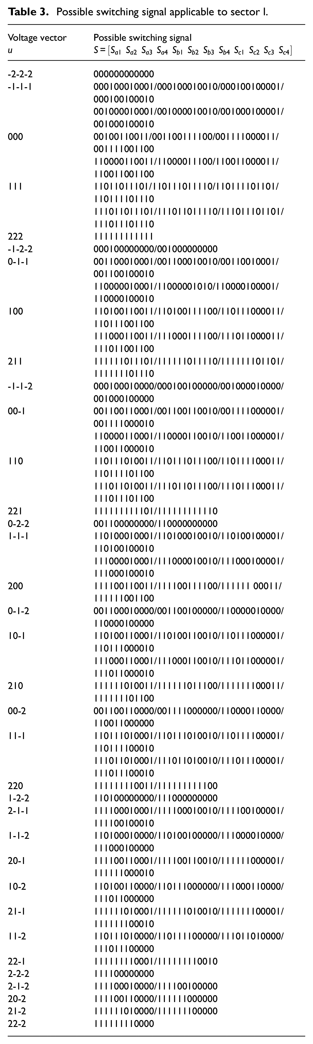
In the final stage, the optimal switching state of the inverter is realized by combining the most suitable inverter voltage from the optimization loop and the proposed FC voltage balancing. If the best inverter voltage belongs to the voltage level
Step 1: Determine the required inverter voltage
Step 2: Evaluate the cost function
Step 3: FC capacitor voltage balancing by employing the condition of Table 2.
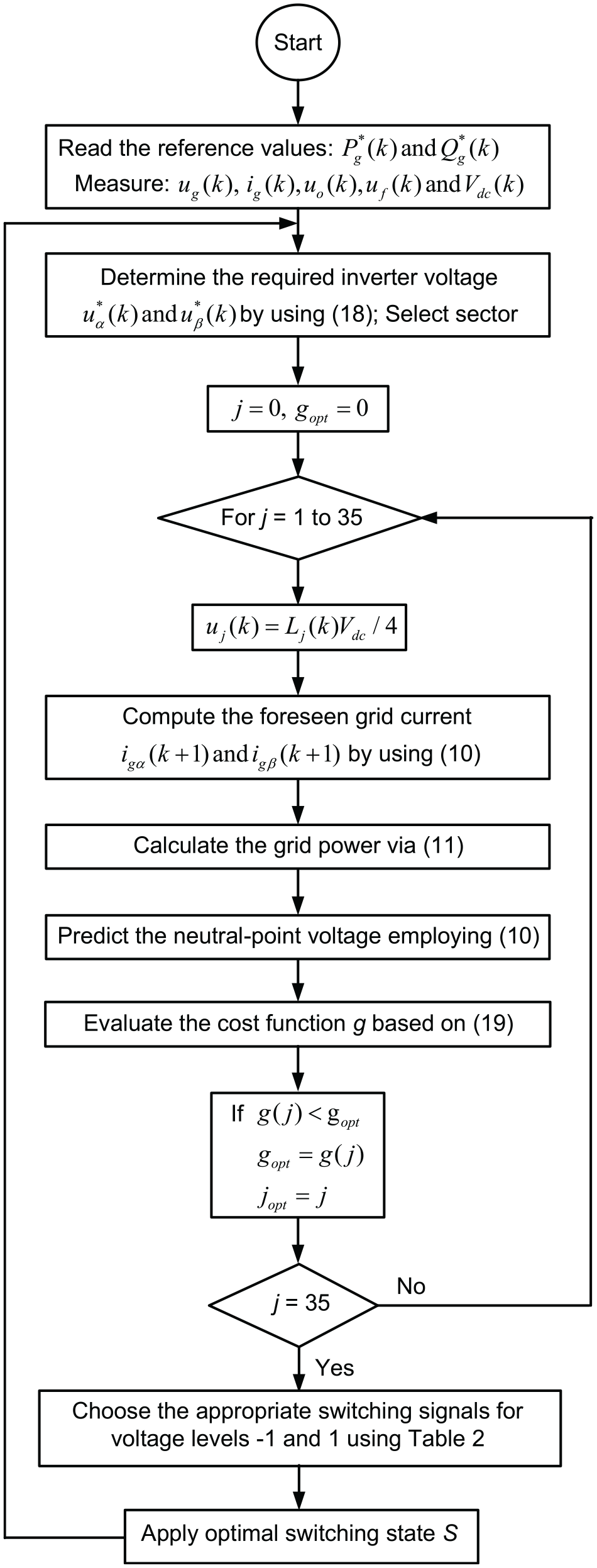
The diagram illustrating implemented proposed method.
Simulation and processor-in-loop results
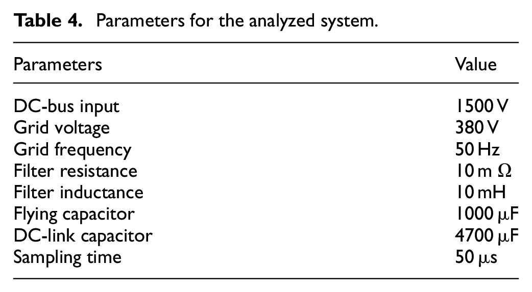
The suggested control strategy’s effectiveness is confirmed in Matlab, whereas the 5L-ANPC inverters are built using Simpowersystem. The parameters associated with the studied approach are detailed in Table 4. The control objectives include tracking the desired grid powers and ensuring the balancing voltage of the DC-bus and FC through dynamic and steady-state conditions.
Parameters for the analyzed system.
Steady-state analysis
The assessment of stable deviation is conducted using the mean absolute percentage error (MAPE), formulated as 12 :

where
The suggested formulation in Rodriguez and Cortes 12 allows for an estimation of the mean frequency of the power switches for the 5L-ANPC inverters as:
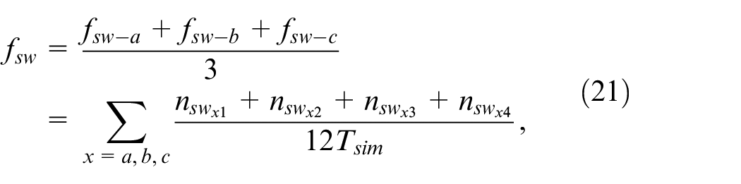
where
Figure 4 displays the consistent achievement of the proposed method at a constant reactive power of 15 kW with operation at a power factor of one. The data presented in Figure 4(a) indicates that the outcome powers can closely track their target with minimal power fluctuations. The MAPE for active power is calculated to be 1.98%, while for reactive power, it is 2.36%. Additionally, the inverter output phase voltage, represented in Figure 4(b), exhibits a step-square waveform. The presented technique effectively generates a high-quality sinusoidal waveform for the grid current, as illustrated in Figure 4(c). The Simulink Fast Fourier Transform (FFT) toolbox is utilized to examine the grid spread and its harmonic spectra under stable conditions. Figure 4(d) demonstrates that the total harmonic distortion of the grid current is 1.15%, meeting the standards specified in the IEEE 519-2014 standard.
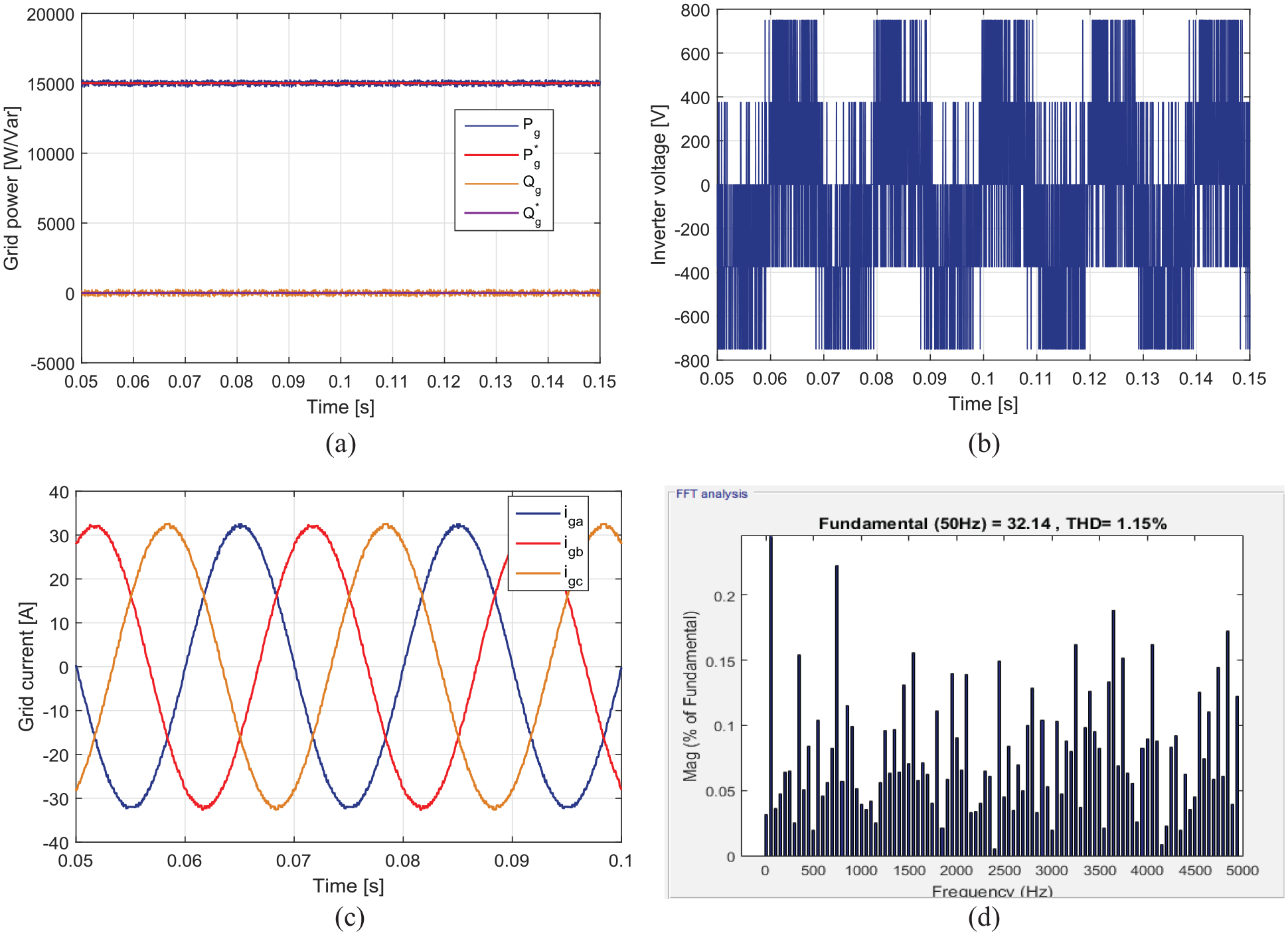
Stable state achievement of the suggested method with
Dynamic analysis
In order to validate that the suggested strategy is both effective and feasible, a comparison is made between it and the standard FCS-MPC,
13
a previous MPC method,
25
and a prior approach
24
under identical operational conditions. The analysis involved switching the active power from 5 to 15 kW at time
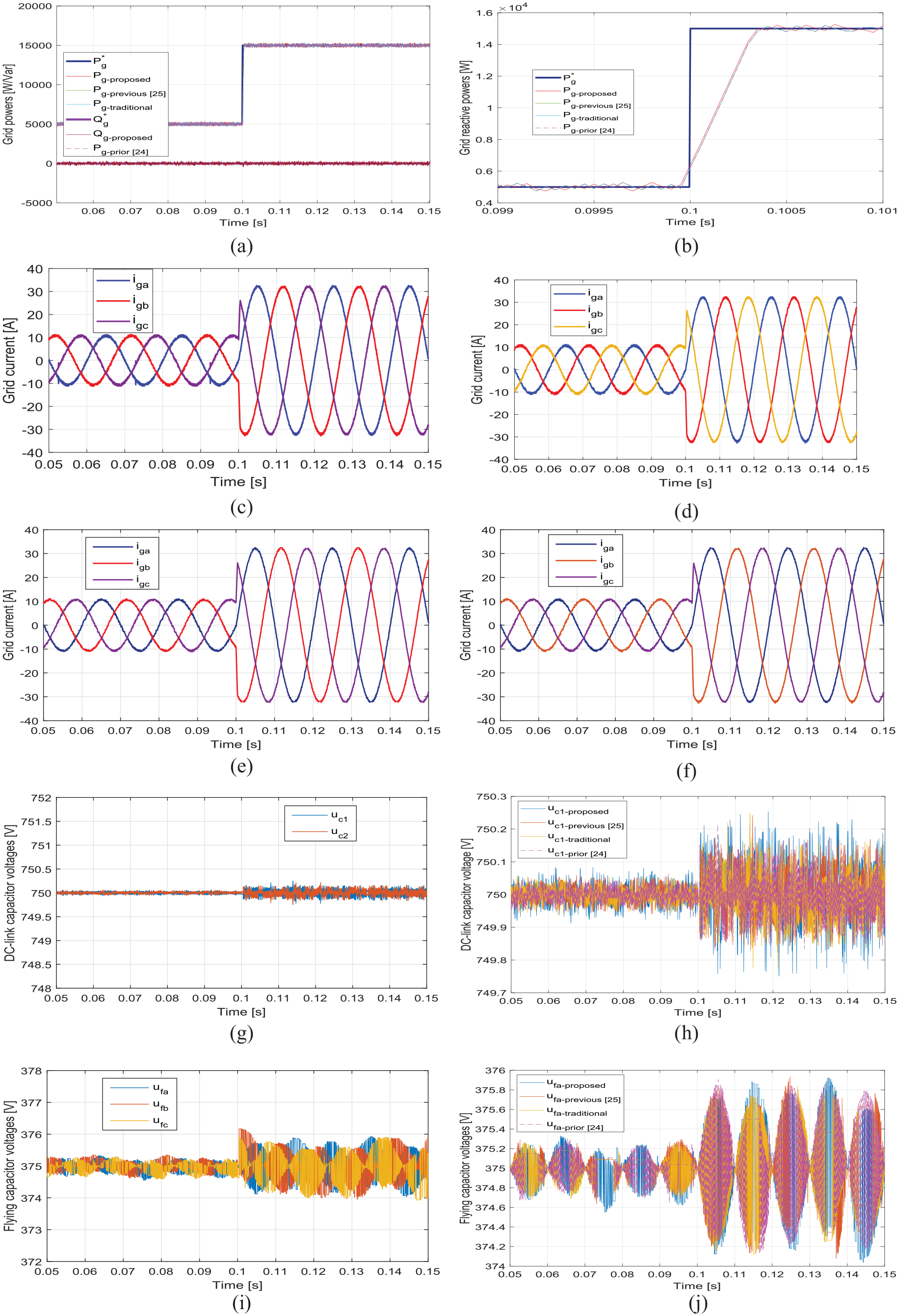
The dynamic reaction to a sudden change in active power: (a) grid power response of four methods, (b) close-up of the active power during the sudden change, (c) grid current of the prior approach, 24 (d) grid current of the previous method, 25 (e) grid current of the suggested approach, (f) grid current of the traditional FCS-MPC, (g) DC-link capacitor voltages of the proposed method, (h) upper capacitor voltages of the DC-bus for four methods, (i) flying capacitor voltages of the proposed method, (j) flying capacitor voltages of phase a for four methods.
In order to further confirm the viability of the presented method, a second study was conducted to examine the impact of varying the power factor. In this investigation, the active power remained constant at 15 kW, while the associated reactive value was adjusted from 0 to 7265 Var at time 0.1 s. The results, depicted in Figure 6(a), clearly demonstrate the effectiveness of the extended approach in accurately tracking such unexpected changes in the power factor. Additionally, it is worth noting that the grid currents, as illustrated in Figure 6(b), maintained their sinusoidal waveform despite the variations, further highlighting the robustness of the proposed approach.
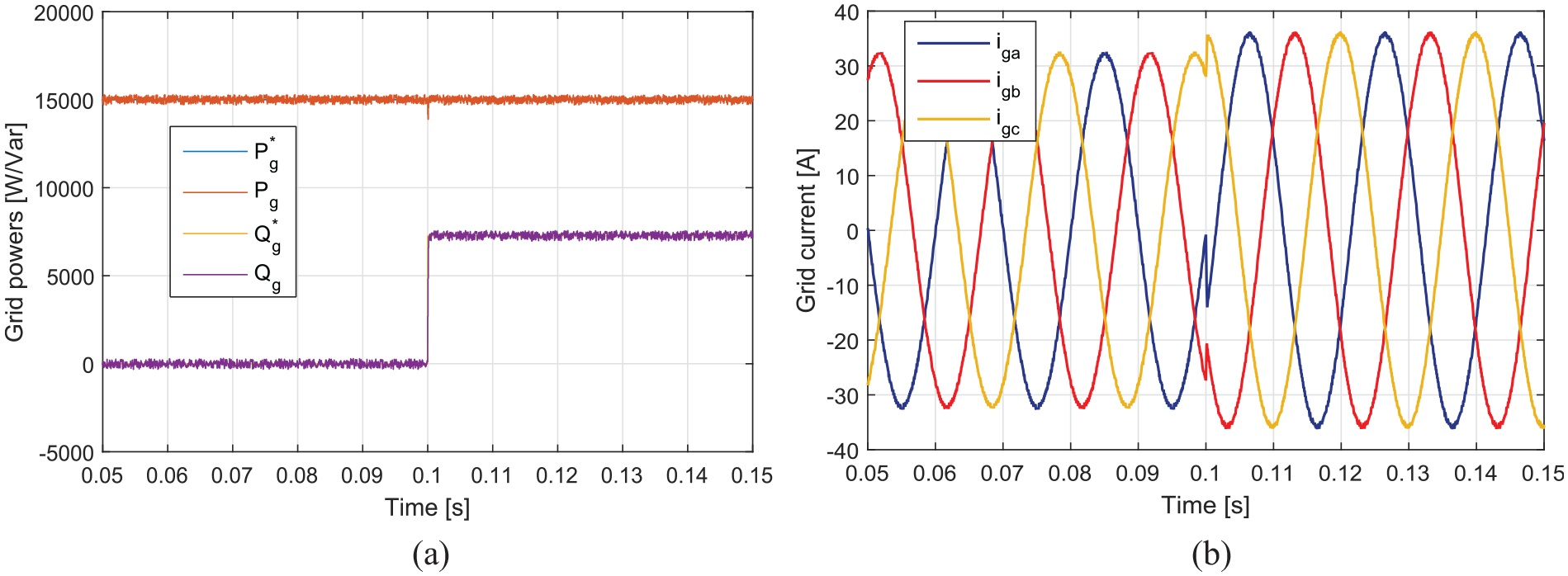
The dynamic behavior of the offered algorithm under different power factor conditions: (a) grid active and reactive powers and (b) three-phase grid current.
Comparison of computation times
In an attempt to confirm the benefits of the suggested approach in reducing computational burden, the tic-toc toolbox in Matlab is utilized to quantify the processing time for three methods. Specifically, employing a 1.6 GHz core i5 8250, the lowest, mean, and highest computation times for the suggested technique are recorded as 4, 17, and 30
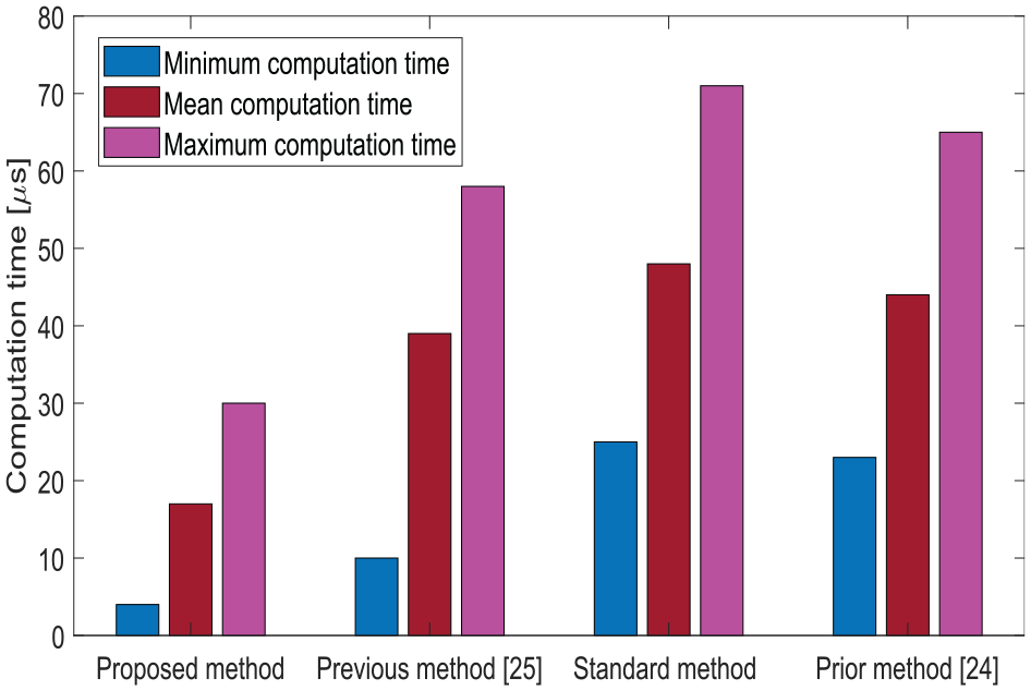
Evaluation of the time taken for computation using four different control methods.
Comparison of the effectiveness of four controllers.
Processor-in-loop verification
This section elaborates on using Processor-in-loop (PIL) verification to determine the practicality of the proposed control approach that incorporates a digital signal processor (DSP) controller. The TMS320F28379D microcontroller from the C2000 series was specifically designed to serve as an PIL emulator, enabling the testing of the proposed system and facilitating a detailed scrutiny of the simulation results.7,32 In this scenario, the PIL emulator operates in a simulated setting, effectively replicating and controlling the configuration components, particularly focusing on the power circuit, which integrates the grid and the 5L-ANPC inverter, facilitated by the Simpower system toolbox. The algorithm awaiting validation is installed within the DSP. Virtual serial transmission ports provide a more streamlined connection between the host system and the real controller. The 5L-ANPC inverters, which are connected to the grid, send their measured signals to the microcontroller board. The controller evaluates these signals to compute the optimal switching status, which is relayed back to the system. Figure 8 presents the fundamental components and signal trajectories pertinent to the PIL simulation of the proposed strategy.
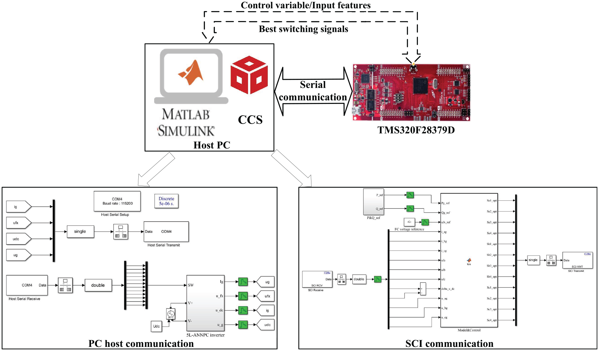
Framework of a PIL testing configuration for a 5L-ANPC inverter integrated with a grid.
Figure 9 presents the findings from the PIL verification of the offered technique. This figure corresponds to a scenario in which the preferred active power of the grid changes from 5 to 15 kW, with a unity power factor at
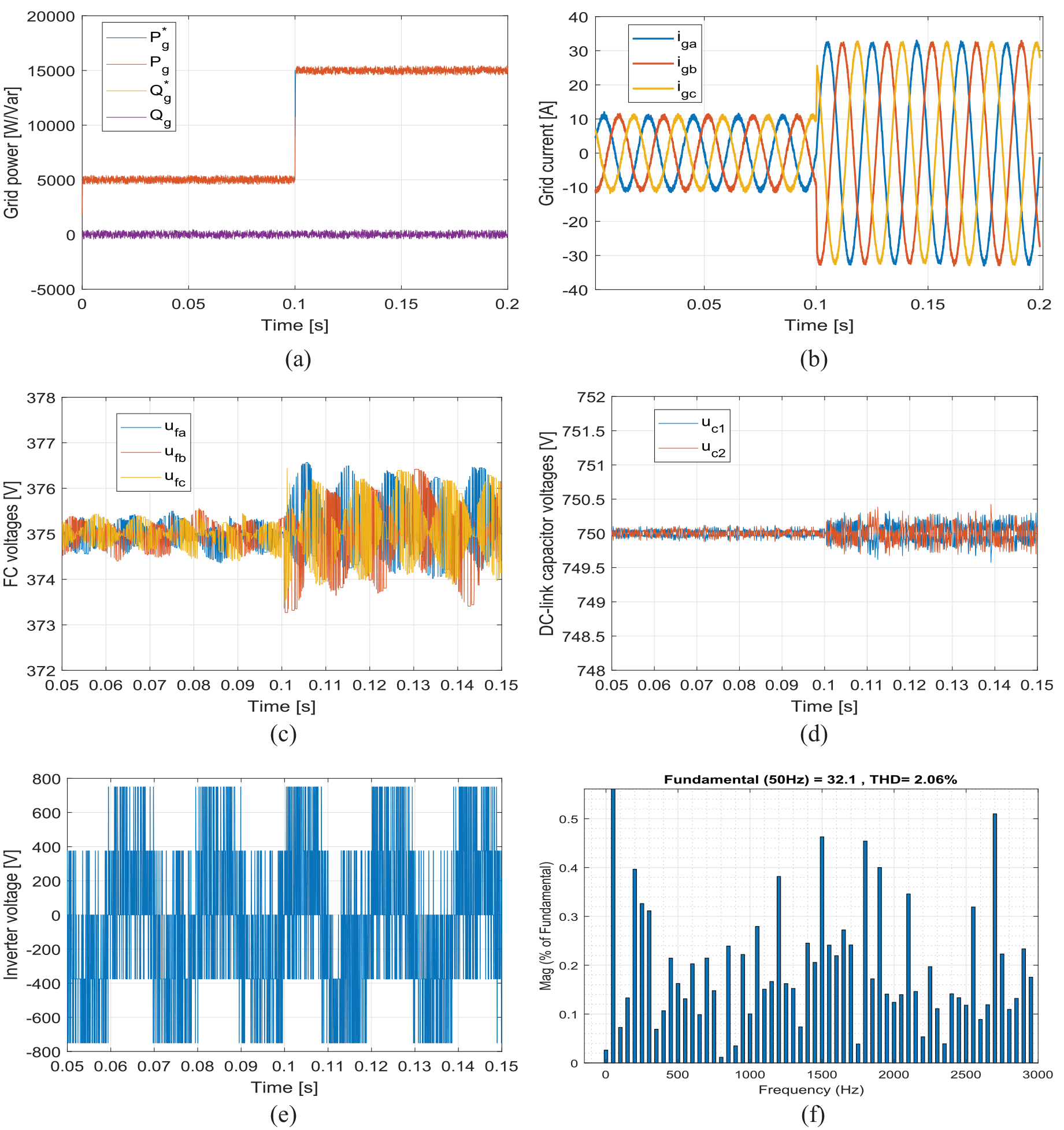
The examination of the recommended technique through the process of PIL verification: (a) grid active and reactive powers: (b) grid current, (c) FC voltages, (d) DC-bus capacitor voltages, (e) inverter output phase voltage, and (f) harmonic spread of grid current.
Conclusions
This paper introduces a scheme-driven FCS-MPC for regulating power transfer in grid-tie 5L-ANPC inverters. The significance of our research is attributed to the integration of the effective FCS-MPC method, aiming to alleviate computational burdens, avoid the challenge of determining multiple optimal weighting factors, and achieve self-balancing FC voltages. This process is carried out in three distinct stages. The first stage involves identifying the sector position of the required inverter voltage by employing predictive power in conjunction with its reference and the grid voltage. In the second stage, the computational complexity is mitigated by refining the cost function through an iterative loop of 35 potential voltages. The final stage results in determining the optimal switching state of the inverter, achieved by integrating the most appropriate inverter voltage from the optimization loop with the suggested FC voltage balancing. The proposed strategy demonstrates performance comparable to conventional FCS-MPC in both dynamic and steady-state conditions, effectively regulating power ripples and the THD of the grid current while achieving a substantial reduction in computational costs of 91%. An improvement in steady-state performance was observed with the proposed algorithm when compared to existing methods. The MAPE of power ripples was lowered by 3.41% and 14.66% when evaluated against the previous method 25 and the earlier approach, 24 respectively. The offered approach yielded a THD of 1.15% in the grid current in contrast to the 1.28% reported in the method from Wu and Wang 25 and the 1.43% noted for an alternative technique. 24 The corresponding decrease in computation time is 56.4% and 61.36%. Our work proposes a structure for deploying the FCS-MPC method on an affordable control platform with a limited sampling interval. These findings might aid in developing a feasible control methodology for MLIs with high-power applications. This approach does not take into account the conditions of the distorted grid. Future research will focus on conducting experiments under these circumstances.
Footnotes
Appendix
Declaration of conflicting interests
The author(s) declared no potential conflicts of interest with respect to the research, authorship, and/or publication of this article.
Funding
The author(s) disclosed receipt of the following financial support for the research, authorship, and/or publication of this article: This work was supported by the Hue University under the Core Research Program [Grant No. NCM.DHH.2022.08].
Data availability statement
Data sharing not applicable to this article as no datasets were generated or analyzed during the current study.