
Abstract
This article demonstrates the fabrication of large-scale micro-structures by two-photon polymerization with an integrated long-stroke precision stage. We first design a three-axial stage that combines a piezoelectric transducer stage and a stepper-motor stage, and we apply gain-scheduling and robust control with a feedforward compensator to achieve nano-positioning within a travel range of 10 cm. We then integrate the precision stage with a two-photon polymerization module to manufacture large-scale micro-structures, including 1 mm linear gratings, 1 cm parallel lines, and 200 µm Fresnel zone plates. We further define performance indexes to evaluate the qualities of these products: the linear gratings achieve an image error of 4.73%, while the 1 cm lines have an average error of 0.2 µm with a standard deviation of 0.05 µm, and the Fresnel zone plates attain a focal error of 0.4% and a focus efficiency of 64%. These results confirm the effectiveness of the proposed use of the precision stage and two-photon polymerization for large-scale micro-structure manufacturing.
Keywords
Introduction
Precision positioning is increasingly important as technology develops and has been applied in industrial applications using advanced control techniques. For example, Yen et al. 1 designed fuzzy scheduling control to improve hard-disk tracking ability. Zhang et al. 2 developed an H∞ almost disturbance decoupling controller with a tracking differentiator for hard disk drive (HDD) head positioning. The experimental results demonstrated the suppression of high-frequency sine disturbances. Herrmann et al. 3 introduced a discrete-time nonlinear adaptive neural network to improve track following and disturbance rejection of a hard-disk system and showed significant reduction in the errors at the first and second nodes.
Another frequently used actuator for precision engineering is the piezoelectric transducer (PZT) which has many favorable properties, such as large driving forces and fast responses with high resolution. For instance, Leng et al. 4 developed a disturbance observer for estimating environmental disturbances and applied H∞ control to attain precise positioning with a static error of ±8 nm. Jeong and Park 5 designed an ultra-precision stage supported by flexure hinges and derived H∞ control to attain a resolution of less than 5 nm. Li and Tian 6 proposed a bridge-type mechanism to amplify PZT displacements and designed proportional–integral (PI) control with fuzzy algorithms to acquire a tracking error of less than 0.02 µm. However, the PZT displacements are limited and might constrain large-scale applications. Therefore, much research has combined PZT and large-stroke actuators. For example, Ito et al. 7 proposed a dual stage that consisted of a linear motor and PZTs inside a CD/DVD laser pickup head and attained a static error of 15 nm with a travel distance of 500 mm. Lin et al. 8 combined PZT with an XY gantry stage and applied iterative learning control to achieve a tracking accuracy of 4 µm within a travel of 30 cm. Kwon et al. 9 presented a dual stage that consists of a PZT stage and a motor stage and designed a robust perturbation compensator. Yang et al. 10 combined a PZT and a high-speed linear motor to achieve a moving speed of 250 mm/s for a 300 × 300 mm stage. Wang et al. 11 discussed the impacts of different sensor layouts for a combined stage that consisted of a PZT stage and a motor stage. The results showed that a modified sensor layout with loop-shaping robust controllers can achieve a root-mean-square error (RMSE) of 5 nm and a misalignment error of 16 nm for a 10 cm travel.
Micro-structure manufacturing has been developed for decades, with various fabrication techniques and applications. For instance, Pan et al. 12 proposed a process that combined laser-induced plasma-assisted ablation with chemical corrosion to make micro-channels with micro-texture surfaces on glass surfaces. Ha and Yang 13 used a three-dimensional (3D) laser scanning method to make open structures with a functional perspective. Dubov and Boscolo 14 designed buried micro-structure waveguides for fabrication in lithium niobate crystal (LiNbO3) by laser inscription. Rong et al. 15 provided novel periodic hexagonal pyramids on single-crystal silicon by chemical etching.
Another useful technique for fabricating micro-structures is two-photon polymerization (TPP), which is initiated by two-photon absorption (TPA) that simultaneously absorbs the photon energy to stimulate molecules to a higher energy level and solidify the radiation-exposed resin to obtain specific structures. For instance, Du et al. 16 developed a hybrid TPP fabrication method to make a 0.5 mm grating. Sun and Kawata 17 improved the resolution of TPP by considering the 3D voxel images and fabricated 3D micro-structures. Wu et al. 18 used TPP to improve the fabrication of a conventional aspheric micro-lens by femtosecond laser micro-nanofabrication. Chung et al. 19 also used TPP to fabricate a 5 × 5 micro-lens array. Wang et al. 20 integrated TPP with a long-stroke precision stage to fabricate 100 × 100 µm linear gratings and Fresnel zone plates (FZPs) with a radius of 47 µm.
This article extends these ideas to discuss the fabrication of large-scale micro-structures by TPP using a long-travel precision stage. The stage consists of a nano-precision PZT stage and a long-travel step-motor stage that achieves nano-positioning within large travels. We further apply gain-scheduling, robust loop-shaping control, and feedforward compensation to improve the positioning performance. We then integrate the combined stage with a TPP module to fabricate large-scale micro-structures, including 1 mm linear gratings, 1 cm parallel lines, and 200 µm FZPs. We further define performance indexes to discuss the fabrication qualities. This article is arranged as follows: section “System descriptions” describes the PZT stage, the stepper-motor stage, and the TPP module; section “Stage identification and control design” derives mathematical models and designs controllers for the stages; section “Stage integration and experiments” combines the PZT and motor stages and conducts experiments for precision positioning; section “Micro-fabrication by TPP” integrates the combined stage with the TPP module to fabricate micro-structures, including linear gratings, parallel lines, and FZP. We also propose performance indexes to evaluate the qualities of these samples; section “Impacts of controllers on fabrication performance” discusses the influences of different controllers on these performance indexes. Finally, we draw conclusions in the final section.
System descriptions
This section introduces the system components, including the PZT stage, the stepper-motor stage, and the TPP module. We combine a two-dimensional (2D) PZT stage and a 3D motor stage to achieve nano-positioning over long travels. We further integrate the combined stage with a TPP module and fix the laser to fabricate micro-structures. The integrated system is shown in Figure 1(a), with the specifications as illustrated in Table 1.

System specifications.

PZT: lead zirconate titanate; TPP: two-photon polymerization.
The structure of the combined stage is illustrated in Figure 1(b), where we apply data acquisition (DAQ) for transmitting sensor and control signals and Visual Studio C++ 2010 to implement the designed controllers. The PZT stage is driven by analog voltage signals (
The structure of the TPP module is shown in Figure 1(c), 19 where the laser is filtered by the attenuator and adjusted by the beam expander. The dichroic mirror reflects the laser with a specific wavelength, and the objective lens focuses the laser beam into the resin. We fabricate micro-structures by moving the stage and observing the processes through the complementary metal-oxide semiconductor (CMOS) camera. An inverted OLYMPUS IX51 microscope is adopted to provide a solid frame for mounting the laser module and the objective lens. The specifications of the laser module and materials are illustrated in Table 1. We switch the laser power by dividing the manufacturing paths into several segments. For instance, referring to Figure 1(c), we make three vertical lines by the following procedures: turning on the laser and moving the stage along some segments (1, 3, and 5) and switching off the laser during other segments (2 and 4). The laser-off time that presents the delay between paths is preset before the manufacturing processes. 19
Stage identification and control design
This section derives the transfer functions of the PZT stage and stepper-motor stage by identification experiments. We then select the nominal plants and design robust control with feedforward compensators and gain-scheduling control to improve the system performance.
Identification of the stage models
We derive the transfer functions of the stages by applying input swept sinusoidal signals with specific amplitudes and frequency ranges and measuring the corresponding output signals. For the PZT stage, the input voltage signal has an amplitude of 1 V with a frequency range of 0.01–100 Hz. For the motor stage, the input signal has an amplitude of 10,000 pulses per second (pps), with a frequency range of 0.01–20 Hz. The input and output signals are shown in Figure 2, where the y-axis responses are not illustrated because they are similar to the x-axis responses.
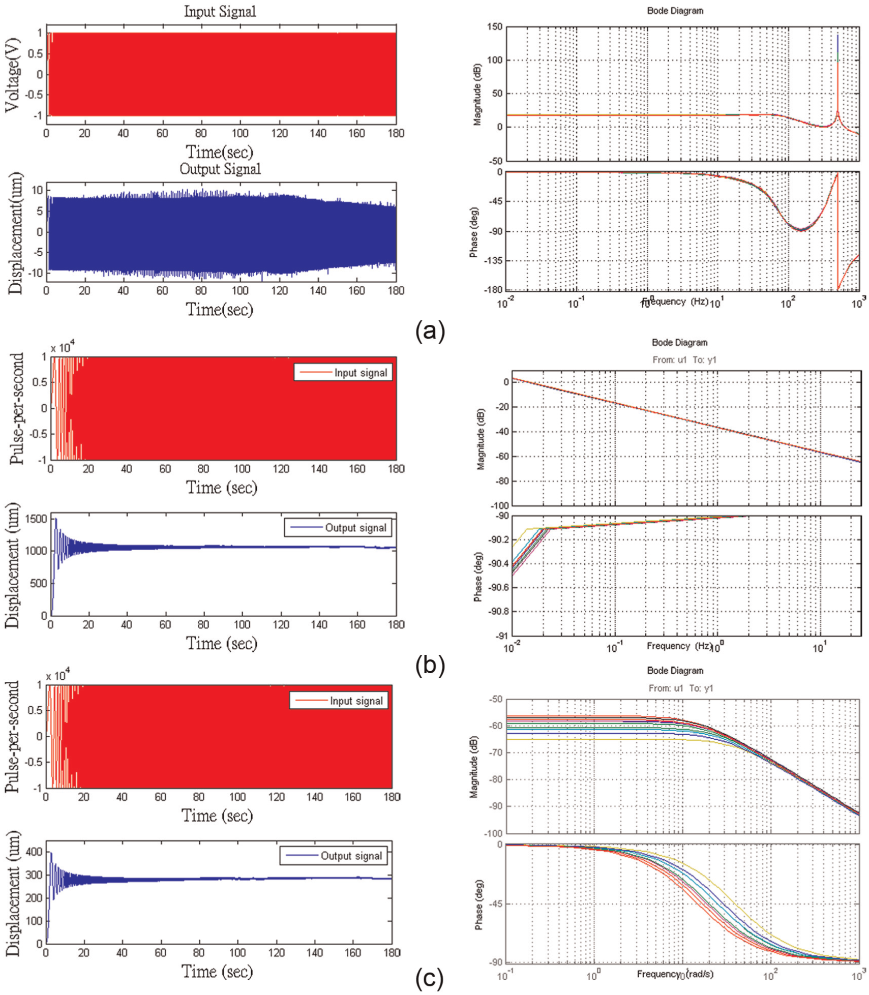
Input/output signals and Bode plots for system identification: (a) x-axis of the PZT stage, (b) x-axis of the motor stage, and (c) z-axis of the motor stage.
We apply the numerical subspace state-space system identification (N4SID) 21 to derive their transfer functions. Considering the system uncertainties, we repeat each experiment 10 times and represent the model transfer functions as follows
where
We note the model variation of the PZT and stepper stages in Figure 2. Therefore, we can consider the systems as linear models with uncertainties that are described by a gap metric. Assume that a nominal plant has a left coprime factorization (LCF) 22 as follows

where

in which
The smallest value of
Thus, we can select the nominal plant

Considering the models identified from Figure 2, we can select the nominal plants as follows

where
Robust control with feedforward compensator for the motor stage
A closed-loop system with a perturbed plant

Thus, we can further define the system’s stability margin

Therefore, the system is internally stable for all uncertainties if and only if
We apply the loop-shaping technique 25 to improve system performance. The main idea is to increase system gains at the low-frequency range for disturbance rejection and to decrease system gains at the high-frequency range for noise attenuation. In addition, the slope of the magnitude plots around cross-over frequencies should not be steeper than −40 dB/decade for stability consideration. We iteratively adjust the weighting functions and verify the system performance by experiments, and we select the following weighting functions for the motor stage

The corresponding robust controllers are designed as

with the stability margins of
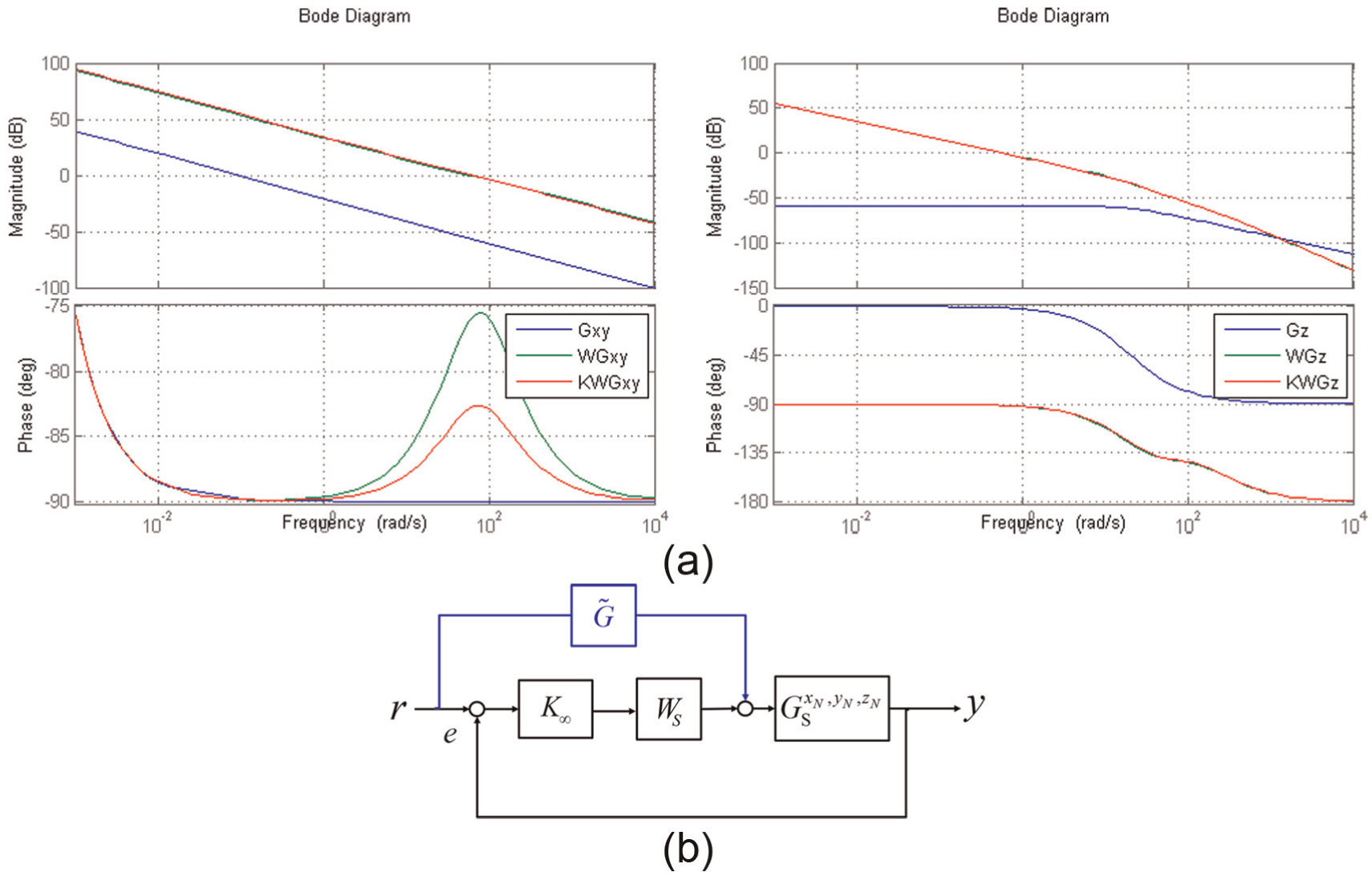
Control design for the stepper-motor stage: (a) Bode plots for robust loop-shaping design and (b) the feedforward compensator.
We note from Figure 3 that the phase lags at the high-frequency ranges, which might result in delayed responses. Therefore, we design a feedforward compensator, as shown in Figure 3(b), to improve the tracking performance. That is, the closed-loop transfer function

by setting the compensator
Gain-scheduling control for the PZT stage
The PZT stage has high resolution and is used to improve positioning and tracking precision. Therefore, we apply an integral to eliminate the steady-state errors, with the following varied gain

The gain is decided by the tracking errors because the system should have fast transient responses to adjust system errors and smooth steady-state responses to attenuate noise and disturbances. Note that the parameters are selected by iterative experiments.
Stage integration and experiments
This section integrates the PZT and the stepper-motor stages and designs a sensor layout to improve system performance, as shown in Figure 4.

Control block diagram: (a) x- and y-axes and (b) z-axis.
In the x- and y-axis, as shown in Figure 4(a), we use a double-loop structure, in which the motor stage makes large displacements and the PZT stage provides subtle adjustments. We apply robust control with feedforward compensation for the motor stage, and we use gain-scheduling control for the PZT stage. In addition, we design a local sensor layout that summarizes the encoder signals to obtain the global displacements. The misalignment errors of the encoders are compensated by a global interferometer sensor to improve manufacturing precision. 11 We also apply the anti-locking function to prevent the PZT stage from exceeding its maximum stroke. In the z-axis, as illustrated in Figure 4(b), we only use the motor stage because the z-axial movement is used to compensate the tilting errors with the scale of micrometer.
Tilting correction
In Figure 1(a), the adaptor can be slightly oblique during operation, as illustrated in Figure 5(a). Therefore, we need to compensate for this tilting phenomenon by converting the commands to a new coordinate system, as shown in Figure 5(b). Assume the laser beam is on the Z-direction and the stage surface is on the oblique plane of ABC, which has rotating angles of

The tilting effects and correction: (a) the tilting effects and (b) the tilting model.
Therefore, the tilting effect can be corrected by the following transformation

Hence, the input command becomes

where
Tracking experiments
We conduct two experiments to inspect the tracking ability of the combined stage. First, we use the stage to draw the characters “NTU,” as shown in Figure 6(a), which have a scale of 100 mm × 50 mm. The corresponding commands on the x- and y-axis are illustrated in Figure 6(b) and (c), respectively, while the errors of the stepper-motor and the combined stage are shown in Figure 6(d) and (e), respectively. The statistical data are given in Table 2, where we compare the RMSEs of the combined stage and the motor stage. The RMSEs have been significantly decreased from 5.00 µm (9.82 µm) to 204 nm (940 nm) in the x-axis (y-axis).

2D tracking experiment: (a) character drawing, (b) x-axis command, (c) y-axis command, (d) stepper-motor errors, and (e) combined stage errors.
Experimental results of stage tracking.
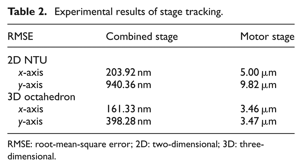
RMSE: root-mean-square error; 2D: two-dimensional; 3D: three-dimensional.
Second, we use the stage to track a three-dimensional octahedron with a scale of 10 mm × 10 mm × 1 mm, as shown in Figure 7(a). The corresponding commands on the x-, y-, and z-axes are illustrated in Figure 7(b)–(d), respectively. The statistical data are shown in Table 2, where the RMSEs have also been improved from 3.46 µm (3.47 µm) to 161 nm (398 nm) in the x-axis (y-axis). The RMSE on the z-axis is 1.69 µm which is larger than the other two axes because there is no PZT on the z-axis to compensate the errors. Based on these experiments, the PZT stage can effectively reduce the positioning errors and improve the stage precision.

The 3D tracking experiment: (a) the 3D plot, (b) x-axis commands, (c) y-axis commands, and (d) z-axis commands.
Micro-fabrication by TPP
In this section, we apply the combined stage to the TPP module to make the following micro-structures: linear grating, parallel lines, and FZPs. We also show the scanning electron microscope (SEM) images of these products to inspect the quality of these samples by the proposed performance indexes.
Linear grating
We fabricate two kinds of linear gratings: 0.5 mm with a pitch of 50 µm and 1 mm with a pitch of 100 µm. The experimental result of the 0.5 mm is shown in Figure 8(a), where the maximum error is less than 1 µm. We binarize the image (see Figure 8(b)) and compare it with an ideal image model (see Figure 8(c)). The image percentage error is defined as follows

where

Image error estimation for the 0.5 mm linear grating: (a) the SEM image, (b) the binary image, (c) the ideal model, and (d) image error.
Parallel lines
We test the precision of large-scale commands by making 1 cm parallel lines with gaps of 0.6 and 1.2 µm, as shown in Figure 9(a). The magnified picture of the 0.6 µm gap is shown in Figure 9(b). We binarize the SEM image (see Figure 9(c)) and detect the edges (see Figure 9(d)) to estimate the distances between the parallel lines. For example, the image has a resolution of 1280 × 1024 pixels, and the distance between the two lines can be calculated through the scale conversion from pixels to lengths. Hence, we obtain 1280 distance records from Figure 9(d), whose average and deviation are 1.07and 0.02 µm, respectively. We take five images in different sections along the 1 cm travel and illustrate the results in Table 3, where the average distances for the 1.2 µm (0.6 µm) parallel lines are 1.35 µm (0.8 µm). The standard deviations at each section are smaller than 0.05 µm, which indicate the gap remains steady. Because the resin sample needs to be washed and dried after laser fabricating, the gaps between the lines might vary significantly.
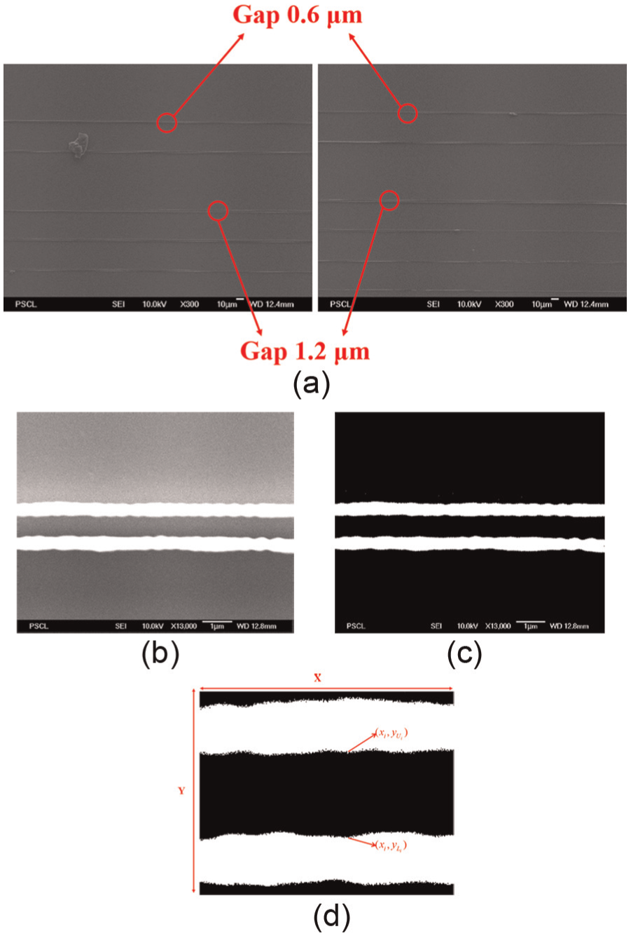
Image processing for the parallel lines: (a) the SEM images, (b) 0.6 µm gap, (c) binarization, and (d) edge detection.
Image gap data.

FZPs
The FZP is a planar micro-lens designed to focus light. We design a FZP with a radius of 99.4 µm to focus the 632.8 nm wavelength red light at an ideal focal length of 500 µm. 20 The experimental results are shown in Figure 10(a). We propose the following performance indexes to quantify the quality of the FZP sample:
Focal error

where
Intensity and sharpness: we observe the light spot at the ideal focal length with the CMOS camera, as shown in Figure 10(b). The intensity is the image brightness along the red line, while the sharpness is the derivative of the intensity curve, as shown in Figure 10(c).
Focus efficiency: the focus efficiency

where
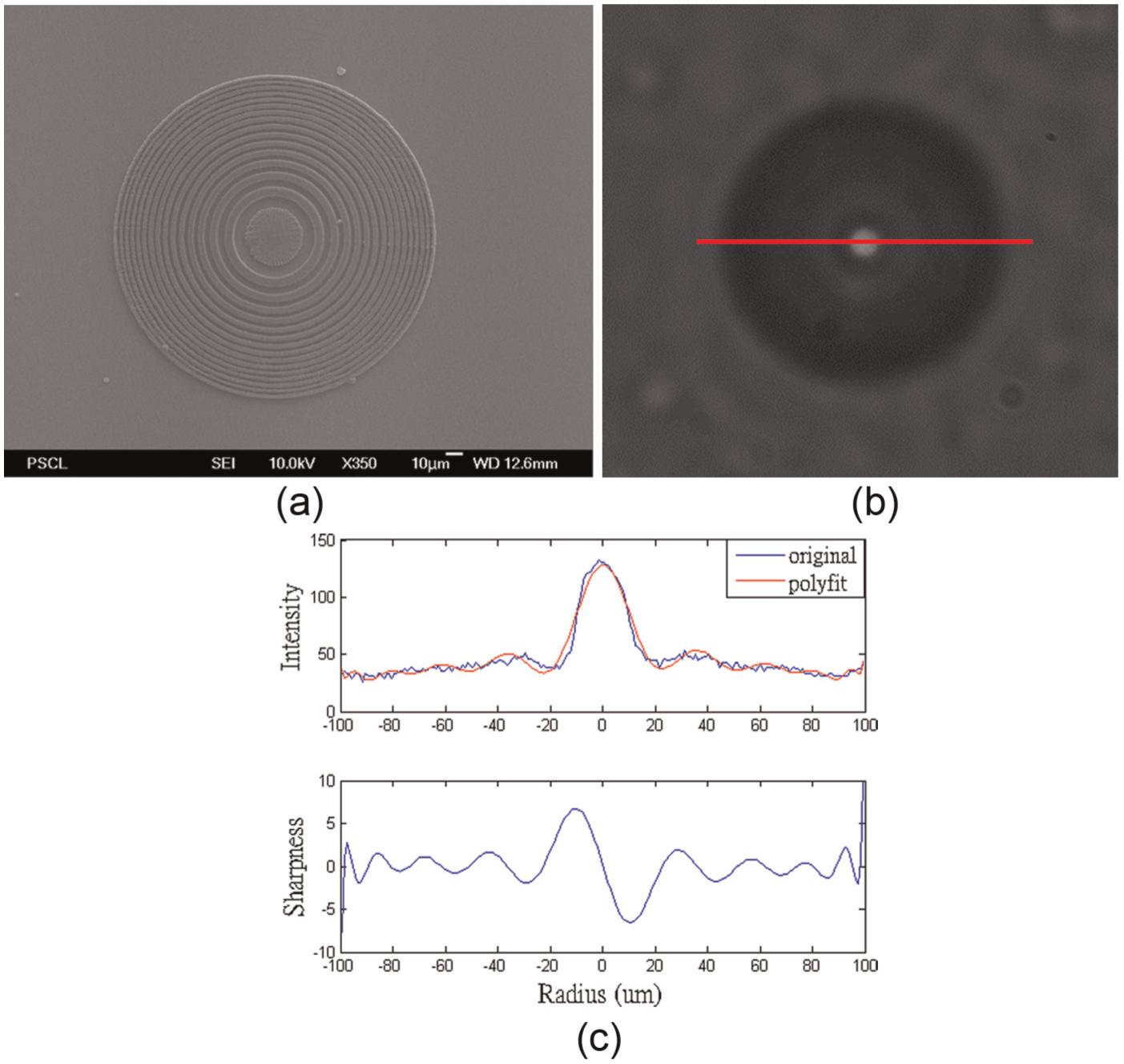
FZP and optic performance: (a) SEM image, (b) focal spot from CMOS, and (c) intensity and sharpness.
A fine FZP should have a small focal error, high intensity, high sharpness, and high focus efficiency. For example, the FZP sample in Figure 10(a) has a focal error of 0.4%, a sharpness of 9.151, and a focus efficiency of 64.74%. In the next section, we will use these performance indexes to discuss the effects of controllers.
Impacts of controllers on fabrication performance
This section discusses the influence of controllers on the manufacturing performance based on the previously described indexes. We use the PZT stage for the fine tuning and the z-axis motor-stage to adjust the tilting effect; therefore, our discussion will focus on the x- and y-axial motor-stage control. We apply five different weighting functions, as illustrated in Table 4, to design robust controllers for the x- and y-axes.
The weighting functions for robust control design.

We implement these controllers to fabricate 0.5 mm linear gratings. The SEM images are shown in Figure 11(a), and the quantified data are listed in Table 5. First, the image percentage error is improved from (i) to (v) because their gains are increased to provide better command tracking and disturbance rejection. Second, the RMSEs and the rise time are also improved from (i) to (v). That is, these two specifications can be used to evaluate the effects of controllers on grating performance without taking SEM images in the future. We further apply controllers (iii)–(v) to make larger 1 mm linear gratings, as shown in Figure 11(b) and Table 5. It is clear that controller (v) provides the best performance.
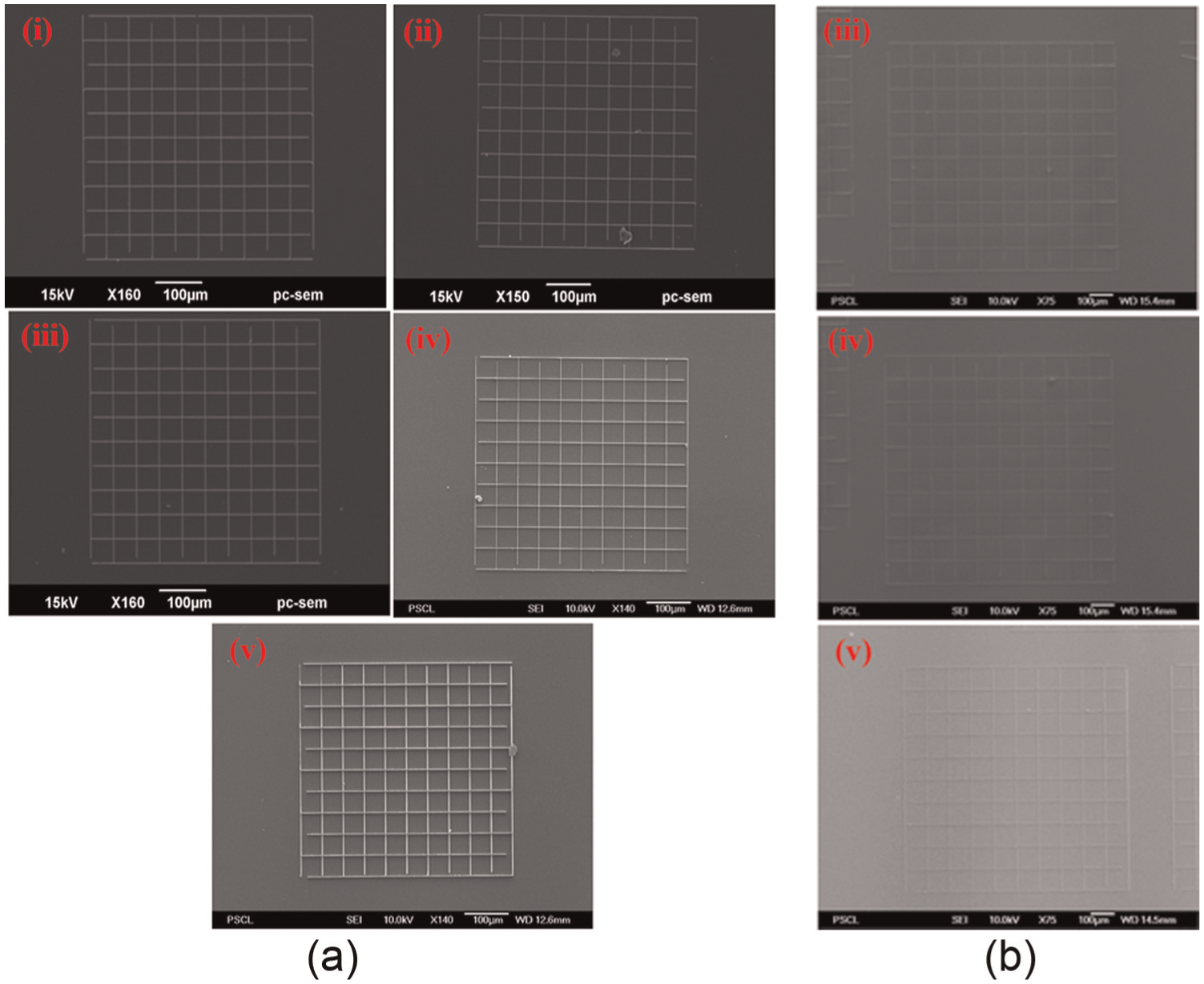
SEM images for linear gratings by different controllers: (a) 0.5 mm and (b) 1 mm.
Impacts of controllers on linear gratings.

RMSE: root-mean-square error.
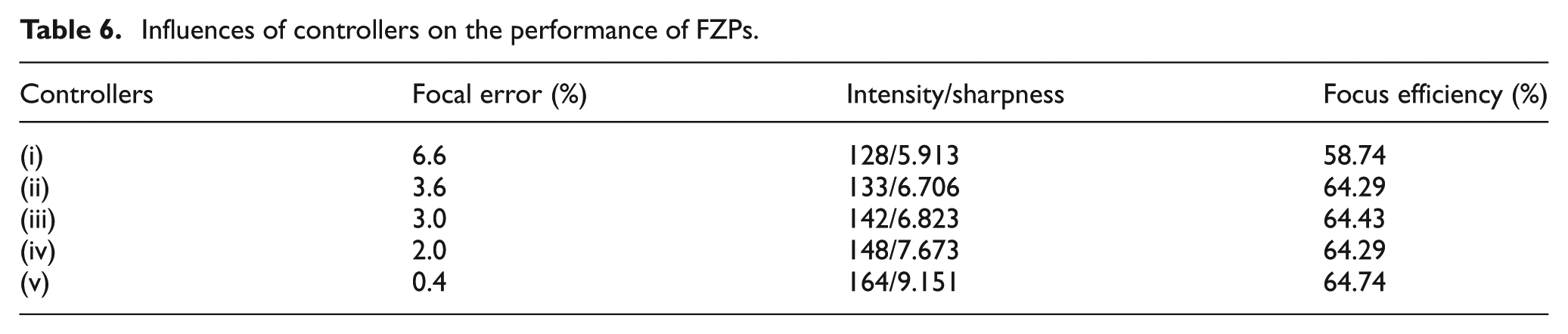
We also apply these controllers to fabricate the FZPs. The SEM images and their intensities/sharpness are shown in Figure 12, and the performance indexes are illustrated in Table 6. The focal errors and intensities/sharpness are significantly improved from controllers (i) to (v). That is, we can also use the controller performance to estimate the FZP qualities, without conducting optical examinations in the future. However, the focus efficiency does not show significant differences imparted by these controllers.

FZP SEM images and performance by different controllers: (a) SEM images and (b) intensity and sharpness.
Influences of controllers on the performance of FZPs.
Conclusion
This article demonstrates the fabrication of large-scale micro-structures by a long-stroke precision stage and a TPP module. The long-stroke stage consists of a PZT stage and a stepper-motor stage. First, we derived the transfer functions and designed controllers for the stages. We then combined the stages and conducted experiments to demonstrate the ability to achieve nano-positioning over large travel distances. Second, we integrated the combined stage with a TPP module to make large-scale micro-structures, including 1 mm linear gratings, 1 cm parallel lines, and 0.2 mm FZPs. We also proposed performance indexes to evaluate the quality of these micro-structures. The linear grating achieved a percentage image error of 4.72%, while the parallel lines attained an average error of less than 0.2 µm over a length of 1 cm. The FZP provided a focal error of 0.4%, a sharpness of 9.151, and a focus efficiency of 64.74%. Finally, we discussed the impacts of these controllers on fabrication performance. The results indicated that the fabrication qualities were related to the tracking performance of the controllers. That is, in the future, we can estimate the qualities of micro-structures by the controllers.
Footnotes
Acknowledgements
The authors would like to thank Mr Yi-Kai Peng for helping in the revision.
Academic Editor: Xiaotun Qiu
Declaration of conflicting interests
The author(s) declared no potential conflicts of interest with respect to the research, authorship, and/or publication of this article.
Funding
The author(s) disclosed receipt of the following financial support for the research, authorship, and/or publication of this article: This work was financially supported in part by the Ministry of Science and Technology of Taiwan with grants MOST 102-2221-E-002-150 and MOST 103-2221-E-002-198.