
Abstract
To avoid catenary collision in a multi-rope friction mine hoist, in this study, the relevant hoisting parameters based on the multi-source coupled vibration characteristics of hoisting catenaries are optimized. First, the multi-source coupled vibration characteristics of hoisting catenaries were investigated based on an established theoretical model, indicating that the hoisting acceleration is the weak coupled hoisting parameter, and the constant hoisting velocity, hoisting load, and catenary length are the strong coupled hoisting parameters. Subsequently, a safety threshold of 50 mm for the transverse amplitude of a catenary in this work was defined and the criterion of parameter optimization was established. Finally, by applying the multi-source coupled vibration model of the catenary, the strong coupled hoisting parameters, the constant hoisting velocity, the hoisting load, and the length of the catenary were optimized to make the transverse amplitude of the catenary less than the safety threshold of 50 mm. The proposed methods of parameter optimization may be new constraints to determine the optimal hoisting parameters in the design or maintenance phase of the floor-type multi-rope friction mine hoist.
Keywords
Introduction
With floor-type multi-rope friction mine hoists being popularly applied to coal mines, catenary collision induced by large-amplitude transverse vibrations, which can damage the rope surface and therefore accelerate the rupture of rope, sometimes occurs. As shown in Figure 1(a), a hoisting headframe in coal mines is usually equipped with two sets of floor-type multi-rope friction mine hoist. In addition, a set of floor-type multi-rope friction hoist, which comprises a friction pulley, four hoisting ropes, two sets of head sheaves, three tail ropes, and two skips, is shown in Figure 1(b). The hoisting steel wire ropes between the friction pulley and the head sheaves are named hoisting catenaries which are often the locations where transverse vibrations of hoisting ropes are more intense. As shown in Figure 1(c), due to the large-amplitude transverse vibrations, catenary collision, which can seriously shorten the service life of hoisting ropes, can be resulted. Therefore, the characteristics of transverse vibrations of hoisting catenaries are important to be investigated in order to conduct necessary optimizations and thereby realize the avoidance of catenary collision.

Diagram of a floor-type multi-rope friction hoist: (a) hoisting headframe, (b) assembly layout sketch, and (c) catenary collision.
The hoisting catenaries are moving ropes with constant length. In mine hoists, few scholars have focused on the lateral vibrations of the catenaries and the potential catenary collision. In a single-rope mine drum hoist, Gong 1 proposed that catenary resonance will be excited when an external excitation frequency approaches one mode of natural frequencies of the rope, but he did not study other factors and any optimization measure. However, the dynamic analyses about the transverse vibrations of hoisting rope with variable length have been performed in recent years.2–8
Axially moving hoisting catenaries with constant length in mine hoists can be viewed as taut axially moving strings that offer no resistance to bending. Theoretical analyses about the string vibrations have been studied for a long time.9–13 Furthermore, the theoretical researches concerning the control of transverse vibrations of moving strings have drawn attention of some scholars. Li et al. 14 introduced vibration controllers for an axially moving string system consisting of a controlled span coupled to a disturbed span via an actuator. Chen and Zhang 15 investigated adaptive vibration control for axially moving strings with a tensioner, and they treated the tensioner as an actuator and employed the Lyapunov analysis to design a control law that can asymptotically stabilize the moving string. Nguyen and Hong 16 employed a hydraulic actuator equipped with a damper as the control actuator at the right boundary of the string and therefore studied a robust adaptive boundary control for an axially moving string that shows nonlinear behavior resulting from spatially varying tension. Boundary control of an axially moving string via Lyapunov method 17 and fuzzy sliding-mode control 18 has also been studied.
From the literature studies mentioned above, it can be seen that controls of transverse vibrations of moving strings were focused on the adaptive control and boundary control using an external actuator which needs large amounts of energy supplement. It is worth noting that few literatures have been focused on the dynamic analysis and vibration reduction of hoisting catenaries in a multi-rope friction mine hoist. Considering the control reliability and the high safety required by the industrial field in coal mines, the mentioned existing control measures such as the adaptive control and boundary control are not suitable for the reduction of transverse vibrations of hoisting ropes in large-scale mine hoists.
The engineering novelty of this article is to optimize the hoisting parameters of a multi-rope friction mine hoist according to the vibration characteristics of hoisting catenaries in order to realize collision avoidance. In this work, the source factors influencing the transverse vibrations of hoisting catenaries were first analyzed. A multi-source coupled vibration model was established to investigate the vibration characteristics of hoisting catenaries, and then, the strong and weak coupled hoisting parameters were determined. Finally, according to the multi-source coupled vibration characteristics of hoisting catenaries, the strong coupled hoisting parameters were optimized to reduce the large-amplitude transverse vibrations of hoisting catenaries.
Analysis of source factors influencing transverse vibrations of hoisting catenaries
To investigate the characteristics of transverse vibrations of hoisting catenaries, the source influencing factors must be first determined. According to Gong, 1 rope resonance will be excited when the excitation frequency is close to any of the natural frequencies of the rope. Therefore, in a multi-rope friction mine hoist as shown in Figure 1(b), collision between adjacent catenaries will be certainly resulted in if the catenary resonance occurs. From the above, it can be concluded that the source influencing factors are the factors that influence the external excitation and inner natural frequency of the hoisting catenaries.
In a multi-rope friction mine hoist, due to the inevitable coaxial errors, the transverse vibrations of hoisting catenaries are usually excited by the axial fluctuations of head sheaves or friction pulley. The mathematical formulas of the axial fluctuating displacements of head sheave and friction pulley can be expressed in the following equations

where eh(t) and ef(t) are the axial fluctuating displacements of head sheave and friction pulley with respect to time t, respectively; Ai and Bi are the ith-order axial fluctuating amplitudes of head sheave and friction pulley, respectively; m and θ are the fluctuating order and phase, respectively; and w0 represents the fundamental excitation angular frequency which is also called the rotating frequency of the head sheave or friction pulley. According to equation (1), w0 is determined by the hoisting velocity and the diameter of rope groove. In this study, the diameter of rope groove was not considered as an external influencing factor because it has a constant value. Therefore, the external influencing factors of lateral vibrations of hoisting catenaries can be concluded as the fluctuating amplitude, fluctuating order, and hoisting velocity as shown in Figure 2.
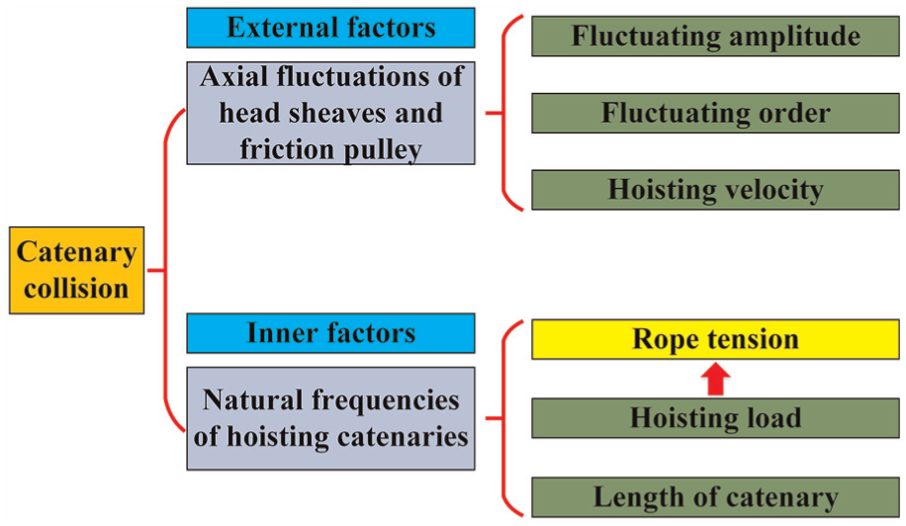
Source factors for transverse vibrations of hoisting catenaries.
The natural frequencies of catenaries are associated with rope tension and the length of catenary. In mine hoists, rope tension is mainly determined by hoisting load. Therefore, as shown in Figure 2, the inner influencing factors of lateral vibrations of hoisting catenaries are the hoisting load and the length of catenary.
According to the above-mentioned analyses, the transverse vibrations of hoisting catenaries are typically multi-source coupled vibrations. To reduce the large-amplitude transverse vibrations of hoisting catenaries and thereby realize collision avoidance, the multi-source coupled vibration characteristics of hoisting catenaries must be first investigated.
Multi-source coupled vibration characteristics of hoisting catenaries
Multi-source coupled vibration model
A theoretical model, which comprehensively considers various coupled factors such as the fluctuating amplitude, fluctuating order, hoisting velocity, hoisting load, and the length of catenary, must be first established in order to investigate the characteristics of transverse vibrations of hoisting catenaries.
Considering that the gravity effect of a catenary can be neglected compared to its large axial tension, the hoisting catenary shown in Figure 1(c) can be modeled as a horizontal axially moving string as shown in Figure 3. In modeling, ef(t) and eh(t), which act as the boundary excitations, are the axial fluctuating displacements of the friction pulley and the head sheave, respectively; v(t) represents the hoisting velocity; and L denotes the length of the catenary.

Axially moving string model with boundary excitations.
Due to the fact that the ratio of the diameter to the length of the catenary is so small, the transverse vibration of a catenary can be viewed as string vibration. According to the literature, 11 a linear model can be used to describe string vibration if the string vibration conforms to the following two assumptions:
The transverse displacements are far less than the length of the string.
The tension of the string is so large that the elastic extension of the string can be neglected.
In floor-type multi-rope friction mine hoists, the maximum transverse displacement of the catenary usually ranges from 0 to 200 mm, which is far less than its length ranging from 40 to 60 m. Compared to the catenary length, the catenary vibration can be viewed as the string vibration with small amplitude, which conforms to the above-mentioned assumption 1. Additionally, in mine hoisting systems, the hoisting load is so large that the elastic extension of the hoisting rope can be ignored, which conforms to the above-mentioned assumption 2. Therefore, according to the literature, 11 the transverse vibration of a hoisting catenary can be governed by the following equation

where ρ, a(t), and T(t) represent the linear density of the catenary, the hoisting acceleration, and the catenary tension, respectively, and the subscripts t and x denote partial differentiation. According to the literature, 19 due to the continuity of rope deflection across the head sheave, the gravity effect can be neglected because the catenary inclination is very small compared to the total quasi-static tension, and the axial tension of a catenary can be approximated by the quasi-static tension at the sheave end of the vertical hoisting rope. In this work, there are four hoisting ropes and three tail ropes. The axial tension of a catenary can be expressed as

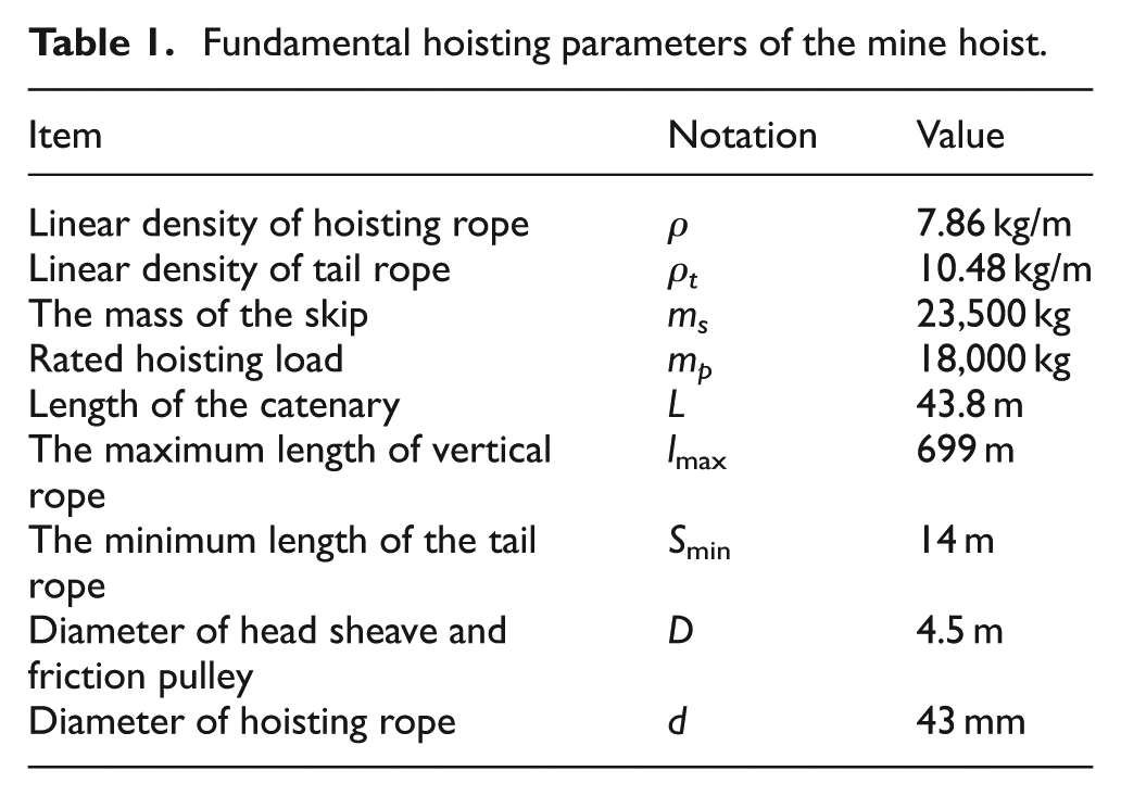
where ms and mp denote the mass of the skip and the mass of the hoisting payload, respectively; ρt is the linear density of the tail rope; Smin is the minimum length of the tail rope; and lmax represents the maximum length of the vertical hoisting rope.
The nonhomogeneous boundary conditions of the governing equation are

To transform the nonhomogeneous boundary conditions into the homogeneous boundary conditions, using the method proposed in the literature, 6 the transverse displacement can be expressed as

where u(x, t) and h(x, t) denote the parts that satisfy the homogeneous and the nonhomogeneous boundary conditions, respectively. According to the literature, 6 the excitation displacement at an arbitrary point of a catenary can be expressed as

Substituting equation (5) into equation (2), the following can be obtained

where f(x, t) is the additional force term after the boundary conditions were homogenized.
By applying Galerkin method, to transform the infinite-dimensional partial differential equation (7) into finite-dimensional ordinary differential equations, a new independent variable ξ = x/L was introduced, and the spatial domain [0, L] with respect to x can be converted to [0, 1] with respect to ξ. Applying assumption modal method, the transverse vibration displacement at an arbitrary point of a catenary at instantaneous time t can be expressed as

where qi(t) and φi(ξ) represent the generalized coordinate and the trial function, respectively, and n is the number of included modes. The partial derivatives of u(x, t) and h(x, t) with respect to ξ and t are

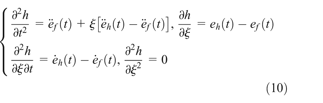
Substituting equations (9) and (10) into equation (7), multiplying equation (7) by φj(ξ) (j = 1, 2, 3,…, n), and then integrating equation (7) over the interval of 0 and 1, the ordinary differential equations can be obtained as follows

where


where the superscript denotes differentiation with respect to time. According to the literature, 20 four-term Galerkin truncation is of enough precise for the solution of linear string vibration; therefore, the included number of modes, n, can be determined as 4 in this case. Eventually, the mathematical formula of the transverse vibration displacement of the hoisting catenary can be expressed as

Model validation
In order to analyze the dynamic properties of the hoisting catenaries and thereby obtain the optimal hoisting parameters, it is imperative to guarantee the validity of the established vibration model.
Real object tests were performed on a multi-rope friction mine hoist with four hoisting catenaries. In this work, using a high-speed camera and the mean shift tracking algorithm which have been introduced in our previous work, 21 the transverse vibration displacements at the center of the lower hoisting catenary 4 (shown in Figure 4(a)) are demonstrated in Figure 4(b), and the corresponding amplitude spectrum is shown in Figure 4(c).
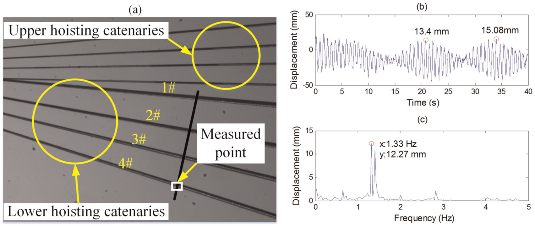
(a) The testing image of catenary vibration, (b) time-domain data, and (c) frequency-domain data.
At the same time, due to the transverse vibrations of the lower catenary 4 that were induced by the axial fluctuations of the lower head sheave 4 or the friction pulley, a measure-distance laser sensor and an inductive displacement transducer were used to detect the time-domain axial fluctuating displacements of the lower head sheave 4 and the friction pulley as shown in Figure 5. With the practical hoisting velocity shown in Figure 6(a), the truly measured axial fluctuating displacements of the lower head sheave 4 and the friction pulley are shown in Figure 6(b) and (c).
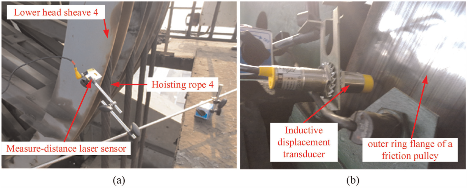
Tests of the axial fluctuating displacements: (a) the lower head sheave 4 and (b) the friction pulley.

(a) The hoisting diagram of the mine hoist, (b) axial fluctuating displacement of head sheave, and (c) axial fluctuating displacement of friction pulley.
To validate the established dynamic model, according to the practical hoisting velocity diagram shown in Figure 6(a), the truly measured external excitation displacements shown in Figure 6(b) and (c) were adopted as the inputs of equations (11) and (16) to calculate the responses of the transverse vibrations at lower catenary 4. The corresponding parameters used were ρ = 7.86 kg/m, L = 43.8 m, D = 4.5 m, and T = 9633.9 × (g + a), where g is the gravitational acceleration and a is the hoisting acceleration. The responses of transverse vibrations at the center of the lower catenary 4 from the established model are shown in Figure 7.

The responses of transverse vibrations at the center of the lower catenary 4 from the established model: (a) time-domain displacement from model output and (b) frequency spectrum of the data from model output.
It can be seen from Figure 7(a) that the time-domain waveform of the transverse vibration at the center of the catenary from the model output is well consistent with the practically measured vibrating waveform as shown in Figure 4(b). The maximum transverse displacement shown in Figure 7(a) is 15.8 mm, which is much close to the practically measured value of 15.08 mm. In addition, according to the simulation result shown in Figure 7(b), the dominating vibration frequency component is 1.33 Hz with amplitude of 8.8 mm, which is close to the measured value of 1.33 Hz with amplitude of 12.27 mm as shown in Figure 4(c). Minor numerical errors induced by detection errors may be acceptable. Therefore, it can be concluded that the established coupled model is valid.
Effects of various hoisting parameters on the vibration characteristics of catenaries
Description of the external excitations
Due to the inevitable coaxial errors, the external excitations of catenary vibration mainly result from the axial fluctuations of head sheaves and friction pulley. According to the literature, 22 angular misalignment such as the coaxial errors may subject the shaft and the component on the shaft to axial vibrations at the 1×, 2×, and 3× r/min frequency. Therefore, the fluctuating order m in equation (1) was determined as 3. A simplified three-stage hoisting diagram is shown in Figure 8. The fundamental hoisting parameters are given in Table 1.
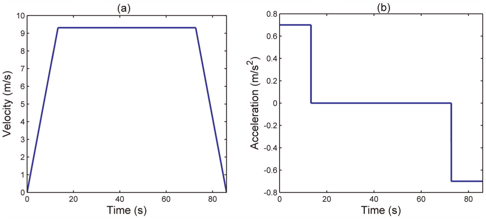
Simplified three-stage hoisting diagram for a mine hoist: (a) hoisting velocity and (b) hoisting acceleration.
Fundamental hoisting parameters of the mine hoist.
Comparison of the responses under the excitations from the axial fluctuations of head sheave and friction pulley
Considering the amplitude difference and phase difference, this part is primarily to compare the effects of the axial fluctuations of head sheave and friction pulley on the transverse vibrations of a hoisting catenary.
Applying equation (1) and ignoring the initial phase of the axial fluctuations of head sheave, the first three-order fluctuating displacements of the head sheave can be expressed as A1 sin(2tv(t)/D), A2 sin(4tv(t)/D), and A3 sin(6tv(t)/D). By introducing a coefficient fco, which is the ratio of the fluctuating amplitude of the friction pulley to that of the head sheave, the first three-order fluctuating displacements of the friction pulley can be expressed as fco × A1 sin(2tv(t)/D + θ1), fco × A2 sin(4tv(t)/D + θ2), and fco × A3 sin(6tv(t)/D + θ3). In numerical simulation, the first three-order fluctuating amplitudes of the head sheave were determined by the maximum permitted value of 4 mm given by the equipment perfectness norm in coal mines, that is to say, A1 = A2 = A3 = 4 mm.
By varying the coefficient fco from 0 to 1 and the phase difference (θ1, θ2, θ3) from 0° to 360°, the numerical responses of the maximum transverse displacements at the center of a catenary under the conditions of no and full payload are demonstrated in Figures 9 and 10.
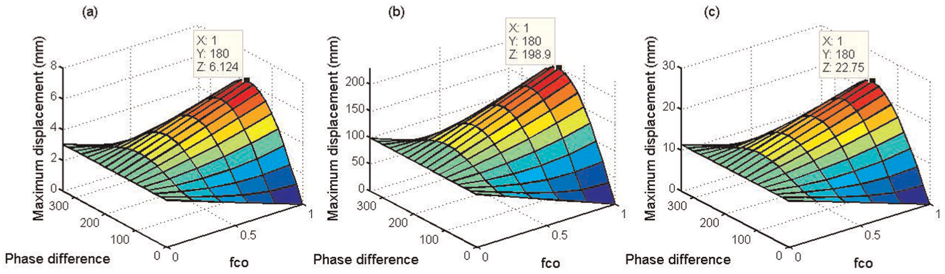
The maximum transverse displacements at the center of a catenary under the conditions of no payload: (a) under the first-order excitation, (b) under the second-order excitation, and (c) under the third-order excitation.

The maximum transverse displacements at the center of a catenary under the conditions of full payload: (a) under the first-order excitation, (b) under the second-order excitation, and (c) under the third-order excitation.
According to Figures 9 and 10, it can be seen that (1) if the axial fluctuating amplitude of the friction pulley equals to that of the head sheave (fco = 1), the maximum transverse displacements of the catenary will vary with the phase difference obviously; (2) if the axial fluctuating amplitude of the friction pulley is far less than that of the head sheave (fco ≈ 0), the axial fluctuating amplitude of the friction pulley and the phase difference can be omitted.
In practical applications, due to the industrial fact that the friction pulley is fixedly installed on the shaft while the head sheave is non-fixedly installed on the shaft, the axial fluctuating displacement of the head sheave is much larger than that of the friction pulley. In this work, by ignoring the influence of the small axial fluctuating amplitude of the friction pulley, the axial fluctuating displacement of the head sheave was adopted as the main boundary excitation to conduct the latter research.
Effects of fluctuating amplitude and hoisting acceleration on the catenary vibration
From equation (2), it can be observed that besides the influencing factors mentioned in Figure 2, hoisting acceleration is also a coupled hoisting parameter for the catenary vibration.
In this section, the effects of fluctuating amplitude and hoisting acceleration on the catenary vibration are investigated. According to the safety regulations in coal mines, the hoisting acceleration should not exceed 1.2 m/s2; therefore, by varying the hoisting acceleration from 0.3 to 1.2 m/s2 and maintaining the constant hoisting velocity of 9.31 m/s unchanged as shown in Figure 11, under the external excitations from the head sheave specified by A1 sin(2tv(t)/D), A2 sin(4tv(t)/D), and A3 sin(6tv(t)/D) mm where the fluctuating amplitudes A1, A2, and A3 were commanded to vary from 1 to 10 mm, the numerical responses of the maximum transverse displacements at the center of a catenary under the conditions of no and full payload with varying accelerations and excitation amplitudes are demonstrated in Figures 12 and 13.

The ascending velocity diagram with different hoisting accelerations.

The maximum transverse displacements at the center of a catenary under the condition of no payload with varying accelerations and excitation amplitudes: (a) under the first-order excitation, (b) under the second-order excitation, and (c) under the third-order excitation.

The maximum transverse displacements at the center of a catenary under the condition of full payload with varying accelerations and excitation amplitudes: (a) under the first-order excitation, (b) under the second-order excitation, and (c) under the third-order excitation.
Effect of fluctuating amplitude
From Figures 12 and 13, it can be observed that during the hoisting process with no and full payload, the transverse vibration displacement of the catenary increases with the increasing fluctuating amplitude of head sheave. However, it can also be noted that there is significant numerical difference of the maximum transverse displacement of the catenary under the different hoisting conditions and different fluctuating orders. Therefore, the fluctuating amplitude of the head sheave, which just acts as the excitation source of the catenary vibration, is not the main factor that excites the large-amplitude transverse vibrations of the catenary.
Effect of hoisting acceleration
From Figures 12 and 13, it can be observed that when the excitation amplitude is a constant value and the hoisting acceleration ranges from 0.3 to 1.2 m/s2, the maximum transverse displacement of a catenary varies ups and downs. To clearly illustrate this issue, according to Figures 12 and 13, when the excitation amplitude is a constant value of 5 mm, a two-dimensional diagram that demonstrates the numerical responses of the maximum transverse displacements of the catenary with varying accelerations is shown in Figure 14.
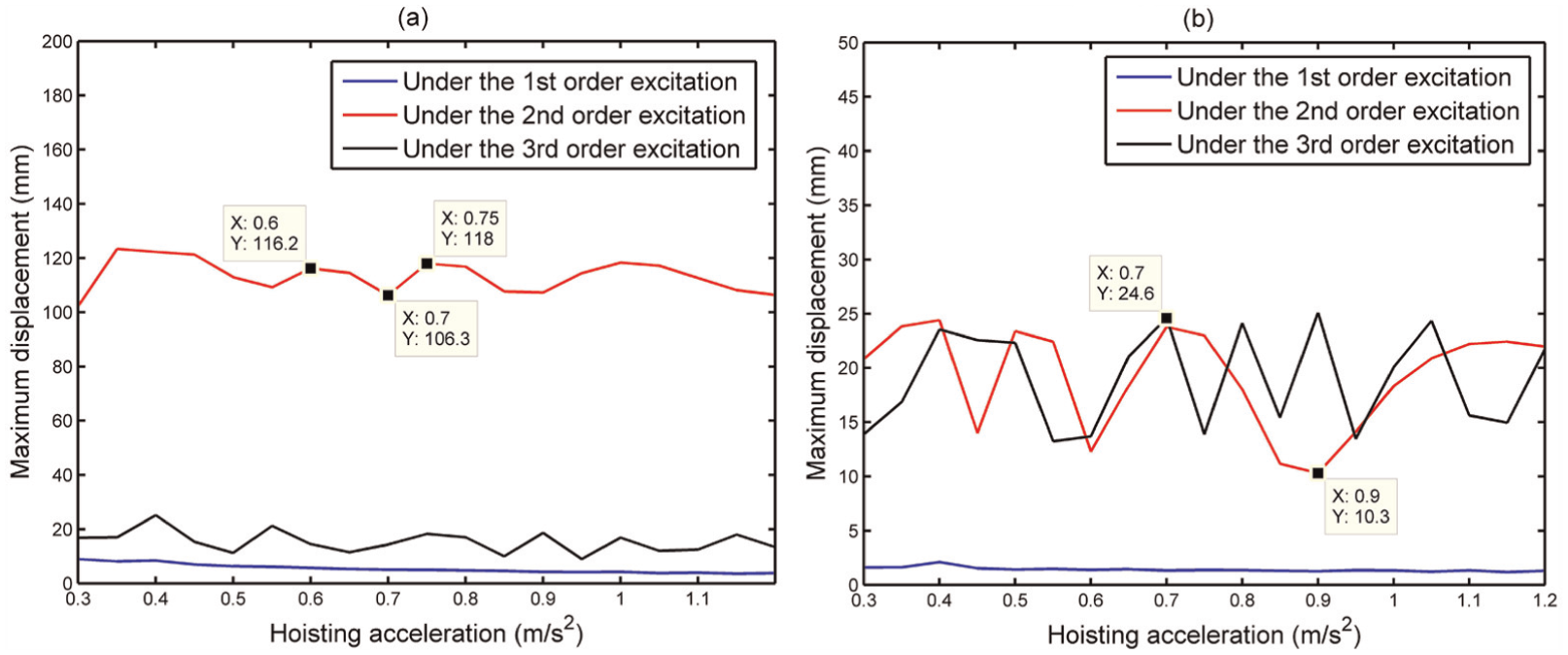
The numerical responses of the maximum transverse displacements of the catenary with varying accelerations when the excitation amplitude is a constant value of 5 mm: (a) with no payload and (b) with full payload.
The following can be observed from Figure 14:
With the hoisting acceleration ranging from 0.3 to 1.2 m/s2, the maximum transverse displacement of a catenary varies, but the peak-to-peak values are small.
The fluctuating order is an important parameter to the catenary vibration; for example, under the circumstance of no payload as shown in Figure 14(a), the maximum transverse displacement of a catenary under the second-order axial fluctuations of the head sheave is obviously larger than that under the first- and third-order axial fluctuations of the head sheave.
Therefore, it can be concluded that the hoisting acceleration is a weak coupled parameter for the large-amplitude transverse vibrations of hoisting catenaries, and the axial fluctuating order of the head sheave is a non-ignorable excitation factor in the investigation and optimization of the catenary vibration.
Effects of hoisting velocity and hoisting load on the catenary vibration
In this section, the effects of hoisting velocity and hoisting load on the catenary vibration are investigated. According to The handbook of chief coal mine engineers, 23 the permitted maximum hoisting velocity of the JKMD-4.5 × 4(III)E floor-type multi-rope friction mine hoist which is the studied machine in this work is 14 m/s. Therefore, the constant hoisting velocity vc was varied from 6 to 14 m/s and the original acceleration of 0.7 m/s2 was maintained unchanged as shown in Figure 15.

Schematic hoisting diagram with varying constant velocities.
Two typical hoisting conditions (no and full payload), which relate to the hoisting payload of 0 and 18,000 kg, were considered. Under the first three-order external excitations from the head sheave specified by A1 sin(2tv(t)/D), A2 sin(4tv(t)/D), and A3 sin(6tv(t)/D) mm, the fluctuating amplitudes A1, A2, and A3 were commanded to be the maximum permitted value of 4 mm given by the equipment perfectness norm in coal mines. The numerical responses of the maximum transverse displacements at the center of a catenary under the conditions of no and full payload are shown in Figure 16.

The maximum transverse displacements at the center of a catenary with varying constant velocities: (a) with no payload and (b) with full payload.
From Figure 16, it can be seen that with the constant velocity increasing from 6 to 14 m/s, there is no obvious difference in the maximum response displacements of the catenary under the first-order excitation, and two spans with discrepant large displacement appear under the second- and third-order excitations. For example, in Figure 16(a), under the second-order excitation, when the constant hoisting velocity is 9.5 m/s, the corresponding response displacement is 477.5 mm which has seriously exceeded the rope spacing of 350 mm in this work and the rope collision will certainly be resulted in.
Additionally, the dangerous spans are different under the two hoisting conditions with different payloads. For example, the dangerous constant hoisting velocities under the second-order excitation according to Figure 16(a) and (b) are 9.5 and 11.3 m/s, respectively.
To clearly address this issue, a calculation formula of the natural frequency of an axially moving string given by Sack 9 is employed as follows

where n is the mode order; ls and ρs are the length and the linear density of the string, respectively; vs is the axial velocity; and Ts is the axial tension of the string.
Considering the dangerous constant hoisting velocities (6.4, 9.5, 7.5, and 11.3 m/s) in Figure 16 and substituting the corresponding hoisting parameters given in Table 1 into equations (3) and (17), the intrinsic frequencies of a catenary corresponding to the dangerous velocities under the circumstances of no and full payload are given in Table 2. The first three-order excitation frequencies from the head sheave corresponding to the dangerous velocities were calculated as shown in Table 3.
Intrinsic frequencies of a catenary corresponding to the dangerous velocities under the circumstances of no and full payload.

The first three-order excitation frequencies from the head sheave corresponding to the dangerous velocities.

According to Tables 2 and 3, for instance, under the condition of no payload (mp = 0), when the constant hoisting velocity is 6.4 m/s as shown in Figure 16(a), the corresponding third-order fluctuating angular frequency is 8.52 rad/s, which equals to the first-order intrinsic frequency of the catenary. It can be concluded that (1) the hoisting velocity has little influence on the intrinsic frequency of the catenary, (2) hoisting load determines the intrinsic frequency of the catenary and the resonance velocity span, and (3) when the constant hoisting velocity locates into the resonance velocity span, a discrepant large transverse displacement will be excited.
Additionally, from equation (17), it can also be noted that the length of the catenary is also an important parameter that can dominantly change the intrinsic frequency of the catenary. Therefore, it can be concluded that the constant hoisting velocity and the hoisting load are the strong coupled parameters to the large-amplitude transverse vibrations of hoisting catenaries.
Optimization of the strong coupled parameters to reduce the large-amplitude catenary vibration
In the design and maintenance phase of the floor-type multi-rope friction mine hoist, to avoid the catenary collision resulting from the large-amplitude transverse vibrations, the strong coupled hoisting parameters such as the constant hoisting velocity, the hoisting load, and the length of the catenary are primarily optimized.
Definition of safety amplitude
So far, due to the existence of various kinds of floor-type multi-rope friction mine hoists with various rope spacings, almost no standard has given a universal definition of safety amplitude for the hoisting catenaries. The JKMD-4.5 × 4(III)E floor-type multi-rope friction mine hoist is the machine that this work focuses on, and the rope spacing of this kind of machine is 350 mm. That is to say, if the sum of the two maximum transverse amplitudes of the adjacent catenaries exceeds 350 mm, catenary collision will certainly be resulted in. Thereby, to be on the safe side, the maximum safety amplitude of a catenary was limited as 50 mm.
Optimization criterion
By varying the corresponding strong coupled hoisting parameters, applying the ordinary differential governing equations of the catenary vibration, and calculating the sum of the maximum response displacements of the catenary under the first three-order excitations, the optimal hoisting parameters that can make the transverse amplitude of the catenary less than the safety threshold of 50 mm can be determined.
The optimization criterion can be formulated as

where R is the sum of the maximum response displacements of the catenary under the first three-order excitations and fi() is the function that represents the maximum response transverse displacement of the catenary under the ith-order excitation.
Determination of the optimal hoisting velocity
In this work, the permitted maximum hoisting velocity of the JKMD-4.5 × 4(III)E floor-type multi-rope friction mine hoist is 14 m/s. Therefore, under the first three-order external excitations from the head sheave specified by 4 sin(2tv(t)/D), 4 sin(4tv(t)/D), and 4 sin(6tv(t)/D) mm, where the fluctuating amplitude of 4 mm is the maximum permitted value given by the equipment perfectness norm in coal mines, by varying the constant hoisting velocity vc from 1 to 14 m/s and considering the three hoisting conditions (no payload, half payload, and full payload), the optimal span of the constant hoisting velocity can be determined as shown in Figure 17.
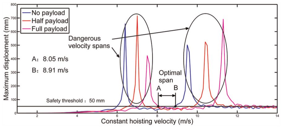
The optimal span of the constant hoisting velocity.
From Figure 17, it can be seen that with the constant hoisting velocity increasing from 1 to 14 m/s, there are two dangerous velocity spans which may make the adjacent catenaries collide with each other. By selecting the constant hoisting velocities that can make the transverse amplitude of the catenary less than the safety threshold of 50 mm, the optimal span from 8.05 to 8.91 m/s was thereby determined. Eventually, the catenary collision can be successfully avoided in the design and the maintenance of the machine. The proposed velocity optimization can be a new constraint in the determination of the hoisting velocity.
Determination of the optimal hoisting load
In coal mines, if a smaller transverse amplitude of a hoisting catenary must be realized by decreasing the hoisting velocity, a lower financial reward will be resulted in due to the decreased yearly output of coal. Under this circumstance, velocity optimization is not an economic way to reduce the catenary amplitude.
Hoisting load, one of the strong coupled hoisting parameters, can be optimized to reduce the large-amplitude transverse vibrations of catenaries without changing the hoisting velocity. Under the first three-order external excitations from the head sheave specified by 4 sin(2tv(t)/D), 4 sin(4tv(t)/D), and 4 sin(6tv(t)/D) mm, where the fluctuating amplitude of 4 mm is the maximum permitted value given by the equipment perfectness norm in coal mines, by varying the hoisting capacity from 0 to 30,000 kg, the optimal span of the hoisting capacity can be determined as shown in Figure 18.

The optimal span of the hoisting capacity.
From Figure 18, it can be noted that when the hoisting capacity varies from 0 to 4078 kg, the maximum response displacements of the catenary are discrepantly large, exceeding the safety threshold of 50 mm. Therefore, to be beyond the dangerous span from 0 to 4078 kg, by maintaining the original rated hoisting capacity of 18,000 kg unchanged, the own weight of the hoisting conveyance can be increased by 4078 kg.
However, the load optimization can reduce the large-amplitude transverse vibrations of catenaries, but at the same time it should be noted that the fatigue life of the rope can be decreased due to the higher mean stress resulting from the increasing preload. In this work, the permitted maximum rope tension of the JKMD-4.5 × 4(III)E floor-type multi-rope friction mine hoist is 900 kN. After optimization, according to equation (3), the maximum rope tension is 176.59 kN which is still far less than the permitted 900 kN. Additionally, according to the literature, 24 to ensure the necessary service life of the mine hoisting rope, the stress value at the arbitrary cross section of the rope should not exceed 165 N/mm2. In this work, the diameter of the rope is 43 mm, and the maximum stress value of the rope can be thereby calculated as 121.6 N/mm2 which is still less than the permitted 165 N/mm2. Therefore, load optimization, which has provided a new constraint in the determination of the hoisting load in mine hoists, can be a good method to realize resonance avoidance of the catenaries without changing the hoisting velocity.
Determination of the optimal length of catenary
The velocity optimization and load optimization have been proposed to reduce the transverse displacement of a catenary, but the two methods have their own advantages and disadvantages, such as the decrease in the hoisting velocity may decrease the yearly output of coal and the load optimization may shorten the service life of the hoisting rope.
The length of the catenary, one of the strong coupled hoisting parameters, can be optimized in the initial design phase of the machine to avoid the potential large-amplitude transverse vibrations of hoisting catenaries without changing the hoisting velocity and the hoisting capacity.
In this work, according to the literature, 24 the maximum length of a catenary is always limited within 60 m. Therefore, by varying the catenary length from 20 to 60 m and considering the three hoisting conditions (no payload, half payload, and full payload), under the first three-order external excitations from the head sheave specified by 4 sin(2tv(t)/D), 4 sin(4tv(t)/D), and 4 sin(6tv(t)/D) mm, where the fluctuating amplitude of 4 mm is the maximum permitted value given by the equipment perfectness norm in coal mines, the optimal span of the catenary length can be determined as shown in Figure 19.
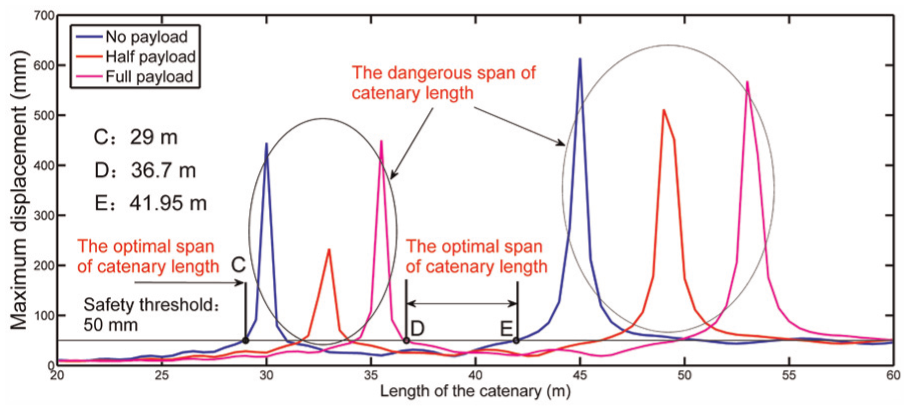
The optimal span of the catenary length.
From Figure 19, it can be seen that with the catenary length increasing from 20 to 60 m, there are two dangerous spans which may make the adjacent catenaries collide with each other. By selecting the catenary length that can make the transverse amplitude of the catenary less than the safety threshold of 50 mm, the optimal spans of 36.6 and 41.95 m and 0 and 29 m were thereby determined. Eventually, the catenary collision can be successfully avoided.
But what we want to emphasize is that the optimization of the catenary is only suitable for the initial design phase of the machine in order to avoid the potential catenary collision. It will also be a new constraint in the determination of the catenary length.
Conclusion
This article mainly focuses on the optimization of hoisting parameters in a multi-rope friction mine hoist in order to avoid catenary collision. First, the source factors influencing transverse vibrations of hoisting catenaries were analyzed, finding out that the transverse vibrations of hoisting catenaries are typically multi-source coupled vibrations. Second, a multi-source coupled vibration model that comprehensively considers the excitation amplitude, excitation order, hoisting acceleration, hoisting velocity, hoisting load, and the length of catenary was established and experimentally validated, and the ordinary differential governing equations of transverse vibrations of a catenary were derived.
Third, based on the established theoretical model, by considering the inevitable fluctuating amplitude and order of the head sheave and the friction pulley, the multi-source coupled vibration characteristics of the hoisting catenary were investigated, revealing that the axial fluctuations of the friction pulley can be omitted when the axial fluctuating amplitude of the friction pulley is far less than that of the head sheave, the hoisting acceleration is the weak coupled hoisting parameter, and the constant hoisting velocity, hoisting load, and catenary length are the strong coupled hoisting parameters.
Finally, to reduce the large-amplitude transverse vibrations of the catenary and then realize the collision avoidance, based on the established safety amplitude and the optimization criterion, by applying the multi-source coupled vibration model of the catenary, the strong coupled hoisting parameters (the constant hoisting velocity, the hoisting capacity, and the length of the catenary) were optimized to make the transverse amplitude of the catenary less than the safety threshold of 50 mm.
To avoid catenary collision and realize the stable operation of the machine, the proposed methods of parameter optimization may be new constraints to determine the optimal hoisting parameters in the design or maintenance phase of the floor-type multi-rope friction mine hoist.
Footnotes
Academic Editor: Anand Thite
Authors note
Jiannan Yao is also affiliated to School of Mechanical and Electrical Engineering, China University of Mining and Technology, Xuzhou, China.
Declaration of conflicting interests
The author(s) declared no potential conflicts of interest with respect to the research, authorship, and/or publication of this article.
Funding
The author(s) disclosed receipt of the following financial support for the research, authorship, and/or publication of this article: This study was supported by National Natural Science Foundation of China (grant no. 51675520). This study was also supported by a project funded by the Priority Academic Program Development of Jiangsu Higher Education Institutions (PAPD).