
Abstract
For the traditional reciprocating pumping unit, it generally starts at the bottom dead point with full load and is accelerated when starting and decelerated when stopping, which not only requires great energy from the motor but also impact on the output torque of motor. In order to tackle the above problems, we propose an energy-saving smooth reversing pumping system, which could store the energy in deceleration by making use of springs, and the stored energy could be reused in acceleration after reversion. This novel system targets to make the motor starting with light load, which could reduce the fluctuation in motor torque, decrease the starting time. In this article, a dynamic model and an efficiency model are established to compute the polished rod load dynamometer card and efficiency of the pumping unit. It is shown that the installed springs could help to reduce the impact on the system when reversing, and significantly decrease the energy consumption. In addition, we set up the real pumping system with load test system to verify the effectiveness of the model establishment. Through the experiment, the proposed pumping system could save energy up to 9.204% as compared to the traditional reciprocating pumping system.
Introduction
With the development of oilfield exploitation, artificial lifting methods by mechanical equipment are becoming increasingly prevalent. 1 In oilfield production, mechanical lifting equipment is one of the major energy-consuming equipment. The 85% of lifting system used in the oilfield production is rod pumping system, which is composed of pumping unit, pumping rod, and motor. 2 In the mid-1920s, Lufkin, a company from the United States, produced the first beam pumping unit in the world. Since then, among the rod pumping system, beam pumping system is widely used traditional pumping equipment. In the system, an AC asynchronous motor is connected to four-bar mechanism and pumping rod through reducer, which could drive the pump under well to do vertical reciprocate motion in order to lift the downhole oil to ground. The beam pumping system has lots of advantages such as simple structure, high reliability, easy maintenance, etc. However, the system owns some drawbacks like low efficiency (around 15%–20%) and high energy consumption.3,4 Additionally, the load exerted to beam pumping unit is periodical alternating load, in which there are big difference between maximum velocity and minimum velocity. Generally, the pumping unit starts from the bottom dead center that requires large moment of inertia. And in the normal working condition, the torque is usually small. However, because we have to choose motor according to the maximum torque required by the system, the output power of selected motor is only one-third of the rated power, which affects the factor of the motor. Furthermore, the load of the pumping system is not equal between up stroke and down stroke. Although the counterbalance could help to improve the imbalance condition, the result is not satisfactory. In practice, in most of the time on down stroke, the pumping unit is driven by the load that makes the motor in state of generator, which severely reduces the system efficiency. 5 To solve the above problems, various pumping systems are introduced by researchers, including back-crank pumping system, suspension biased beam pumping system, belt-driven pumping system, down eccentric barbell pumping system, twin-horse head pumping system, etc. 6 Those systems could only make an improvement in raising system efficiency, but they are not able to solve the above-mentioned problems. In 1990, lively, a company from the United States invented non-beam pumping system and obtained the patent with the title “Long stroke well pumping unit with carriage.” 7 In 2008, linear motor pumping system is developed by Y Gu et al. 8 and Li et al., 9 and so on, which is also a non-beam pumping system. Various non-beam pumping systems have solved the problems because they do not rely on using increased stroke structure, and four-bar linkage structure for reversing. 10 However, there is impact on the output torque of the motor in non-beam pumping system in period of start and stop, which would affect the reliability, system lifespan, and the energy consumption. Therefore, how to further improve the reliability and lifespan of non-beam pumping system is the essential portion of research in this article.
Motivation of these, in this article, we will explore the modeling and experiment on energy-saving long stroke energy storage smooth reversing pumping system. This article is organized as follows. In section “System setup and schematic design,” we provide the system setup and schematic design of the pumping system. In section “ Modeling of the motor output force,” we give an output force model of motor within the system. The polished rod load analysis and efficiency analysis of pumping unit are presented in sections “The polished rod load analysis of pumping unit” and “Efficiency analysis,” respectively. Furthermore, simulation and experimental results are stated in sections “Simulation results” and “experimental results,” respectively. Finally, we conclude our results in section “conclusion.”
System setup and schematic design
For the traditional reciprocating pumping unit, the impact on the output torque of the motor when starting or stopping the unit would increase the energy consumption of the system. To tackle this problem, we offer one solution to achieve rational utilization of energy. The dynamic energy when the pumping unit in the reversing motion could be stored in another mechanical system. And then the energy stored could be reused to accelerate the motor in the pumping system. The proposed solution is presented in detail as follows.
Energy storage system using springs
The schematic diagram of the pumping system is presented in Figure 1. The spring sets (2, 8) are installed in the upper and lower portion of the pumping system frame (3). And the AC frequency conversion motor and reducer (7) are installed on the bottom of pumping unit. On the top and bottom of the pumping system frame, there are sprockets and chain (9). One portion of the chain is fixed with the counterbalance (5). When the sprockets are powered with motor through the reducer, the counterbalance will be moved by the chain. In addition, the pumping rod is connected to counterbalance through belt (4) that is wrapped around the friction gear (1) at the other end. Therefore, when the counterbalance is moving up or down, the pumping rod will move up or down accordingly. Furthermore, the reversing, acceleration, deceleration, and uniform linear motion of the pumping unit are controlled by the electronic control cabinet (6).

Schematic diagram of the pumping system.
When the pumping unit is on the up stroke, the counterbalance is moving downward. The counterbalance then is in contact with the bottom spring set, and continuously moving downward to squeeze the bottom spring set until moving to the bottom dead center. Hence, the elastic potential energy is stored in the squeezed bottom spring set. Then, the motor will rotate in reverse direction, and the pumping unit is on the down stroke, which makes the counterbalance move upward. Obviously, the squeezed bottom spring set will help to accelerate the counterbalance movement until they are disengaged. The counterbalance is in uniform linear motion until in contact with the top spring set. The top spring set would be squeezed by the counterbalance until the top dead center. At this time, the elastic potential energy is stored in the squeezed top spring set. Then, the motor would rotate in reverse direction, and the pumping unit is on the up stroke, which makes the counterbalance move downward. Similarly, the squeezed top spring set will help to accelerate the counterbalance movement until they are disengaged. The counterbalance is in uniform linear motion until in contact with the bottom spring set. The pumping unit will repeat the movement described above continuously.
Velocity curve of the pumping unit
The velocity curve of the traditional linear reciprocating pumping unit is trapezoidal, which is clearly seen in Figure 2. From Figure 3, the acceleration of the traditional pumping unit in the period of start and stop is a constant and the value is a, one can get to zero when the traditional pumping unit is in uniform linear motion. Therefore, there are moments that the value of the acceleration of the traditional pumping unit changes from a to 0 or from 0 to a. The abrupt change in the acceleration could reduce the lifetime of the pumping unit.

Velocity curve (A: velocity curve of the traditional reciprocating pumping unit and B: velocity curve of the energy stored reciprocating pumping unit).

Acceleration curve (A: acceleration curve of the traditional reciprocating pumping unit and B: acceleration curve of the energy stored pumping unit).
In the proposed solution, two spring sets are installed in the pumping system, which changes the velocity curve of the pumping system to be sinusoidal as shown in Figure 2. The resultant acceleration curve is presented in Figure 3. Obviously in Figure 3 curve B, there is no abrupt change in the acceleration, which could reduce the impact on the pumping unit and increase its lifetime.
Modeling of the motor output force
In this section, we only consider some moving components in the pumping system, such as top big friction gears, belt wrapped on the gear, end point of the belt at right-hand side that used to connect with the pumping rod, counterbalance, and top spring set and bottom spring set, which coincides with Figure 1. On up stroke, load on the right-hand side is pumping rod load and load from oil liquid column. While on down stroke, load on the right-hand side is only the pumping rod load (in this case, the load from the oil liquid column is zero). We present the mechanical model of counterbalance and spring sets in Figure 4.
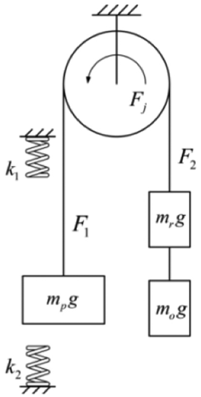
Mechanical model of counterbalance and spring sets.
According to the velocity curve in Figure 2, calculate the output force of motor and the mechanical behavior of the spring sets in six stages (I, II, III, IV, V, and VI).
Up stroke stage (stage I)
Force on the counterbalance can be shown as follows

Among these parameters
Here, the force on the pumping rod and column of oil liquid is expressed as follows

where
If

where
If

Motivated by these, we have

where
When


Here,
Up stroke stage (stage II)
Force on the counterbalance is defined by

Force on the pumping rod and oil liquid column is as follows

If


Up stroke stage (stage III)
From above equations, we have given out the force on the counterbalance of our system as

Force on the pumping rod and oil liquid column is as follows

When

If

where
When


The modeling for stages in down stroke is similar to the modeling for stages in up stroke as presented above. The total distance of the pumping unit in both up stroke and down stroke is computed as follows.
where
The polished rod load analysis of pumping unit
The polished rod load is one of the important parameters to describe the capability of the pumping unit, and it is also crucial in designing and selecting suitable pumping system for real applications.
Static polished rod load


where
Dynamic polished rod load
Here,


where

where the parameter E is the elastic modulus of steel, E = 2.1 × 10⁵ MPa, and
The amount of shortening of oil liquid column is denoted by

where

Here,

where
Vibration load
As we know, the pumping rod is elastomer that can be modeled by a lone spring. Assume that the suspension point is the origin of coordinates. The vibration of the pumping rod can be simplified into the longitudinal vibration of a slender rod with one end fixed and other ends free. 9 The longitudinal vibration of the pumping rod can be described using wave equations as follows

Initial conditions:
Boundary conditions:
The vibration load on suspension point created by the longitudinal vibration of the slender rod can be computed as follows

where
Frictional load
1. Friction force between pumping rod and liquid column.
The friction between pumping rod and liquid column happens on down stroke, which resists the pumping rod moving downward especially when the liquid is thick. The maximum frictional force can be calculated using approximate formula as follows 11
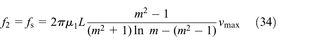
where m is the ratio between inner diameter of pipe and pumping rod diameter.
2. Friction force between liquid and oil pipe.
The friction force between liquid and oil pipe does not directly affect the movement of pumping rod. Nevertheless, it may increase the pressure when the piston moving upwards. Additionally, on account of the liquid flow in the pipe is small on down stroke, the friction between the liquid and oil pipe can be neglected on down stroke. 12
The friction between liquid and oil pipe on up stroke can be computed as follows

where
Efficiency analysis
The work done by the energy storage reciprocating pumping unit
The work done on up stroke is as follows

The work done on down stroke is as follows
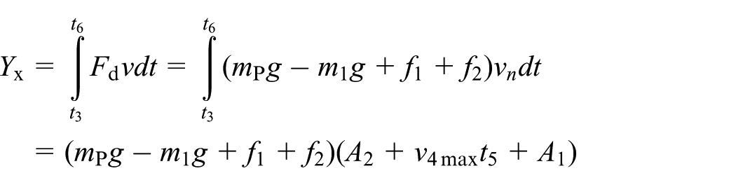
The work done on entire stroke is as follows

where
The work done by the traditional reciprocating pumping unit
Consider the output force of motor on down stroke. In the period of

In the period of

In the period of
The work done by traditional pumping unit on up stroke can be computed as follows 13

where
Consider the output force of motor on down stroke. In the period of

In the period of
In the period of
The work done by traditional pumping unit on down stroke can be computed as follows

The work done in the entire stroke is as follows

The simulation model of system efficiency is as follows 14

where
The effective power of the system
The formula to calculate the effective power recommended by oil industry standard is shown as follows 15
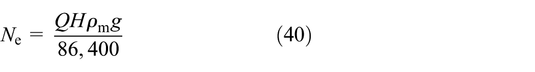
where

where


where D is the diameter of the piston in the pump, n is the number of strokes, and
Simulation results
Assume that
Based on the data in the assumptions above, the dynamometer card of polished rod load of our proposed pumping unit is presented in Figure 5. The dynamic polished rod load of out proposed unit is almost equal to the static load, which means the system is very stable. As mentioned earlier, the output torque of motor in the traditional pumping unit has abrupt change when start and stop the unit, whereas the proposed pumping unit could avoid the unexpected change on output torque of motor. From Figure 6, we can clearly see that the output torque of motor in the proposed pumping unit is very stable with time.

The dynamometer card of polished rod load of energy storage reciprocating pumping unit.

The comparison on motor torque of traditional reciprocating pumping unit and proposed pumping unit.
In the proposed strategy, the energy storage system with spring set could not only assist the motor in reversing motion of pumping unit, but also store the extra energy and reuse it. Therefore, it could reduce the energy consumption as compared to the traditional pumping unit. The energy consumption could be reduced by 10.46% with the proposed energy storage pumping unit shown in Figure 7.

The comparison on system efficiency of traditional reciprocating pumping unit and proposed pumping unit.
Experimental results
Design of the load simulation system
Load simulation system is a device in the laboratory to simulate the force on suspension center of the pumping unit. It can be used to evaluate the performance of pumping system in practice.
Nevertheless, in practice, the value and direction of the velocity and acceleration of the belt are changing with time, which makes it hard to reproduce the loading conditions in the laboratory. Therefore, in order to solve this problem and provide solutions, various researchers have been proposed in several literatures, such as hanging a weight on the polished rod, loading weight on a slope, electric damp loading, etc. However, those methods have some defects such as cannot consider all the components of the polished rod load of the pumping system, weak real time performance, and low accuracy. In our experiment, in order to avoid the defects mentioned above, we make use of actual measured polished rod load dynamometer card to generate the control signal on computer and input it to the control system. Then, the control system will pass the command to the servo valve to control the hydraulic cylinder, which could simulate the actual loading conditions of the pumping system. We aim to utilize the designed loading system in evaluating the static and dynamic performance of our proposed pumping system.
The designed loading system of the pumping unit is actually a servo valve controlled hydraulic system. The loading system is composed of computer control system, servo valve, hydraulic cylinder, force transducer, and signal conditioning circuit, as presented in Figure 8. The computer control system outputs command the servo valve. Then, the hydraulic cylinder does work to the pumping unit controlled by the servo valve. The force exerted on the pumping system is then collected by the force transducer. This signal collected is sent back to the computer control system through signal conditioning circuit. In all, there is a closed-loop control in designed loading system.

Flow chart of the loading system.
The design of test system
The test system is composed of pumping unit and loading system, as presented in Figure 9. The pumping unit is connected to the hydraulic loading system through belt and connection mechanism. The experiment is conducted in our laboratory.

The structure diagram of loading system.
To prevent the counterbalance from swinging, a rail and wheels are added to the pumping unit that ensures the counterbalance moving only in vertical direction. The location arrangement of rail, spring sets, and sensors are shown in Figure 10. The whole pumping system is shown in Figure 11. Additionally, the experiment parameters are presented in Table 1.
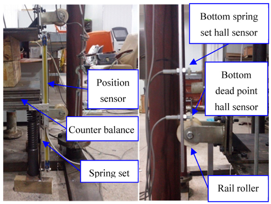
Location arrangement of spring sets and sensors.

Whole proposed pumping system.
Experimental parameters.

The sinusoidal wave, shown in Figure 12, is used to control the speed of motor from starting. The actual speed of motor collected by sensor is shown in Figure 13, which has some fluctuations. We have compared the current collected from motor in the case of pumping system with and without spring sets. From Figure 14, the time used from starting the motor to smooth operation is 1 s. It is obvious that the current of motor is much smaller in the first second from starting when there are spring sets installed in the pumping system. In addition, we have conducted experiment to record the current of motor when the pumping system is nearly reaching the end of up stroke, as shown in Figure 15. From Figure 15, the current of motor is slightly increased when the counterbalance is just contacting with spring set. Then, there is abrupt change in the current until a value maintained by 0.3 s, and finally, the current reduces to zero. We have computed the value of energy saving in whole stroke and the ratio of energy saving is 9.204%, which matches the result with the one obtained in mathematical simulation model.
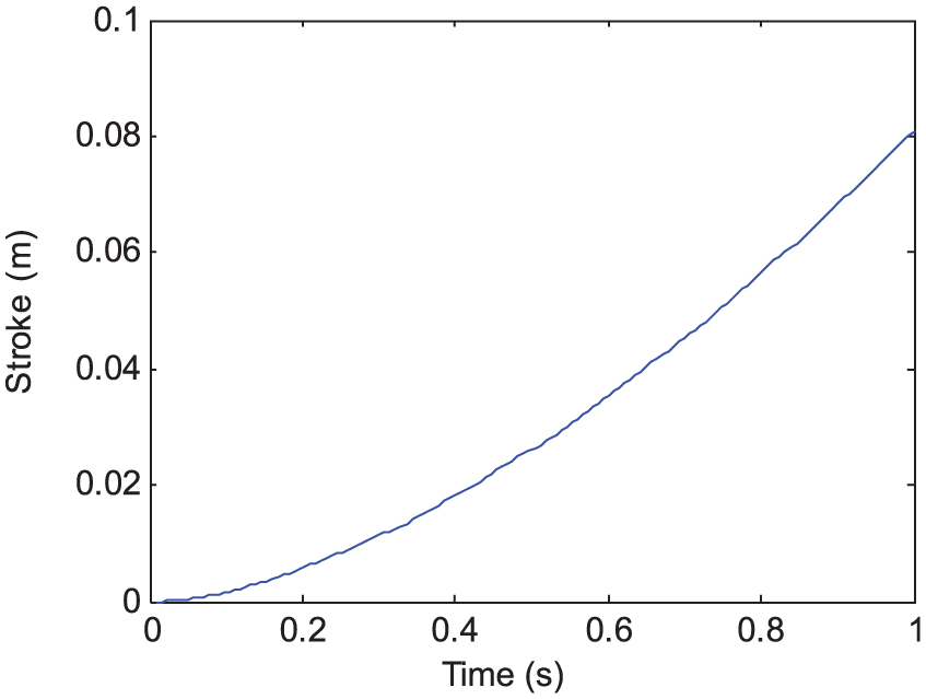
The motor start command signal.

The speed of motor from starting.
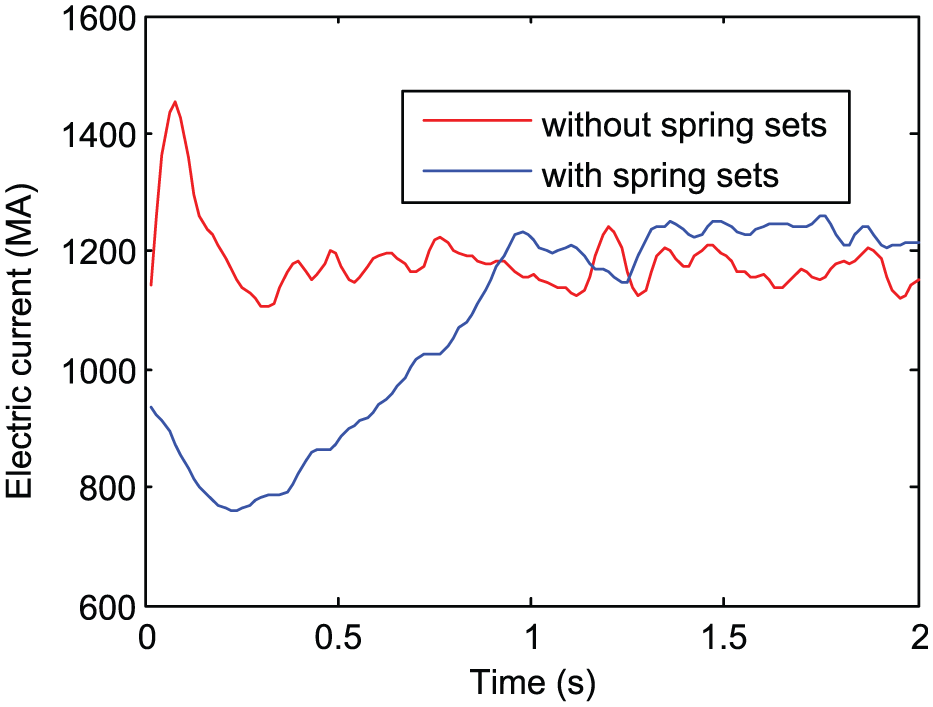
The current from starting the motor in the case of pumping system with and without spring sets.

The current of motor when the motor is decelerating.
Conclusion
A pumping system, with novel springs energy storage devices, has a significant energy-saving effect as compared to the traditional reciprocating pumping system. The development research, including design, modeling, and experiment was done. The conclusions are as follows:
Theoretical estimation and experimental measurement of the ratio of energy saving were carried out. Good matching was observed, and hence the parameters used for the theoretical estimation of the new energy-saving pumping system were validated. Based on characteristic analysis of new energy-saving pumping system, the ratio of energy saving was estimated as 9.204%.
After the pumping system reaching the bottom dead center, it requires a big start torque for the motor to reverse the counterbalance in the traditional pumping system, whereas our proposed pumping system could reduce the start torque of motor, which could increase the lifespan of the motor.
From the experiment, the dynamic polished rod load dynamometer card of proposed pumping system is presented in Figure 5. The dynamic polished rod load matches the static polished rod load in the whole stroke, which reduces the ratio of vibration and inertial energy.
The velocity curve of the motor in proposed pumping system is sinusoidal, which makes the start and stop of the system smoother. Therefore, the proposed strategy could prolong the lifespan of the pumping system.
Footnotes
Academic Editor: Ramoshweu Lebelo
Declaration of conflicting interests
The author(s) declared no potential conflicts of interest with respect to the research, authorship, and/or publication of this article.
Funding
The author(s) disclosed receipt of the following financial support for the research, authorship, and/or publication of this article: This work was supported by the National Natural Science Foundation of China (Grant No. 51605321, No. 51405327) and the Natural Science Foundation for Young Scientists of Shanxi Province, China (Grant No. 2014021024-1).