
Abstract
The multi-type pump configuration equipped with one invert scheme is suitable for the system to operate over a wide range of flow and head at different time periods. Its optimization may be the result of relatively low regulation capability. As a result, a synchronous switch control model was adopted to overcome this defect and to save further energy operation of the pump system. The hardware of synchronous switch control could be achieved by a simple logic control circuit which could be easily programmable and a phase discriminator control circuit which could eliminate the impact current. The software of synchronous switch control could be achieved by the minimum shaft power scheduling model group based on every type pump as variable-speed pump could calculate the optimal operation condition and the minimum switch number could ensure the optimal control regulation scheme. In conclusion, the single invert with synchronous switch control technology was used in an energy-saving reconstruction project of a circulating pump station; it could achieve the gain almost as same as the two invert scheme with the payback time almost the same as the single invert with pony pump scheme. Such is a particularly high quality and reasonable price scheme.
Introduction
Nearly 20.9% of the nation’s electrical energy demand is consumed by pump systems. Thus, pump system should be the highlight of energy reduction and conservation.1,2 In 1970s, some researchers have proposed to use the inverter to adjust the operation of the pump for the operating efficiency visible improvement.3,4
Due to the expensive frequency conversion equipment, one variable-speed equipment with the frequency of water supply was adopted. The wide accepted scheme of multi same model pumps with single invert is improper not only in economy but also in technology. However, some research results show that the multi-type pumps configuration equipped with one invert scheme could have remarkable energy saving effect. 5
However, the multi-type pump configuration equipped with one invert scheme still has a problem—it should operate as variable-speed pump. If the large pump is adopted in the variable-speed pump, then the system could achieve maximum operation ability, and if the small pump was chosen as variable-speed pump, it could achieve high operation efficiency in fine operation course. So, if the variable-speed pump could switch between large and pony pump, it would be an ideal way. 6
At the same time, the synchronous switching control technique between frequency transformer and power frequency electric network has been most widely used in pump system as soft stat-stop device. It is a quite mature technology in engineering practice.7,8
The main work of this study is to apply synchronous switching technique in variable frequency pump real-time switch control. This makes invert to switch between large and pony pump in practical time and to further save energy with almost same initial investment.
The economy of mathematical analysis of the synchronous switch control technology
A pump should be selected so that it operates predominantly closed to the best efficiency point in the so-called “preferred operation range.” This mode of operation is apt to bring about the lowest energy and maintenance cost and to reduce the risk of system problems; hence, it is one of the most important economic indexes that made the whole pump operate in this range.9,10
Math model of the efficient operation area
The range of the preferred continuous operation could be defined, for instance, by the requirement that the efficiency should not fall below 80%–85% of the maximum efficiency of the pump in question, and the allowable ranges could be defined as the efficiency should not fall below 70%.
Considering the general centrifugal pump, the Q–H characteristics could be expressed as follows, considering the preferred operation range11,12

In this interval, the head He and the flow range could be recorded as

When the pump is operated by VFD (variable frequency drive), the range of speed regulation should also be considered. If the speed range exceeds, the operation efficiency will decrease, and the reliability will reduce; hence, the factors of operation should be considered, and the speed regulation range is constrained as [kmin, 1]. 12 The preferred operation range is expressed as shown in Figure 1.

Efficient operation area for the variable-speed pump.
According to the affinity law in pump theory, l1 and l2 are set as similar lines in Figure 1. A, B, C, and D are the boundaries of the operation zone, and the l1 and l2 could be expressed as follows
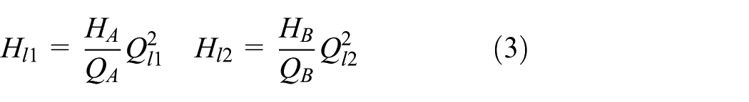
When the head He is needed for this water supply system, then the boundary can be changed as

Parallel operation pump group model
The advantages of multiple pump parallel combinations are flexible, redundant, and capable to meet changing flow needs efficiency in systems. In particular, adjustable speed drive tends to be more efficient to variable demand requirements. As a result, the configuration equipped with an inverter is common in engineering practice.
The operation point of each pump is derived from the intersection of the system characteristic with the combined characteristics of all pumps in operation. In parallel operation, each unit has to pump against the same pressure difference imposed by the system. Thus, the combined characteristic of the pumps is obtained by adding the flow rates of all operating pumps at constant head.
This method can also be used for the operation area by adding each single pump operation area in a head, as shown in Figure 2.

Efficient area of a parallel operation pump group with single inverter.
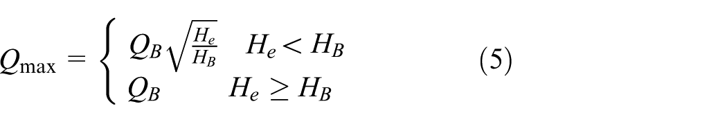
The mathematical model can be shown as follows. When the head He is needed for the water supply system, the boundary can be changed according to equations (4) and (5)

where n is the number of pumps, x expresses the constant speed operation pump, i denotes the ith pump, k is the kth type of pump, and wi is the switch vector. In the configuration of the ith pump selection, if the pump is in operation, we use 1; otherwise, the value is 0.
Economy of mathematical analysis
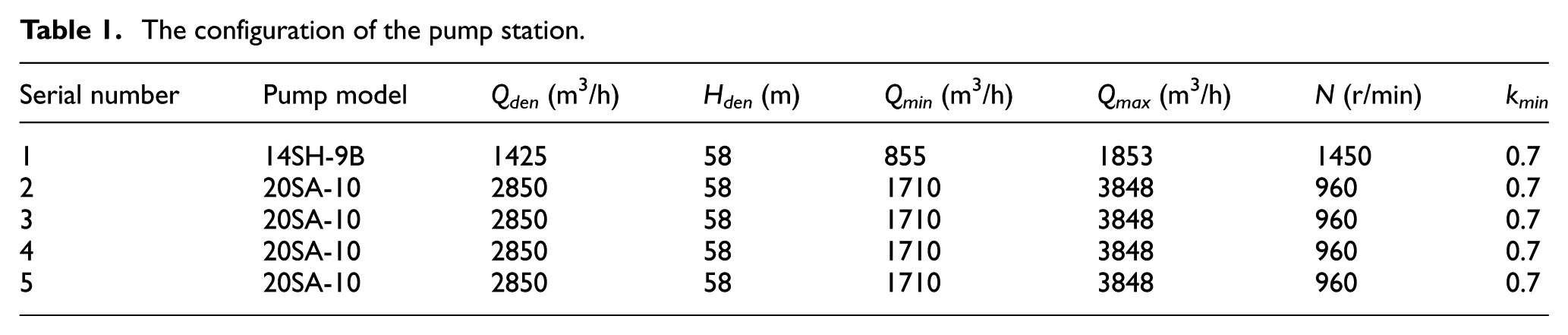
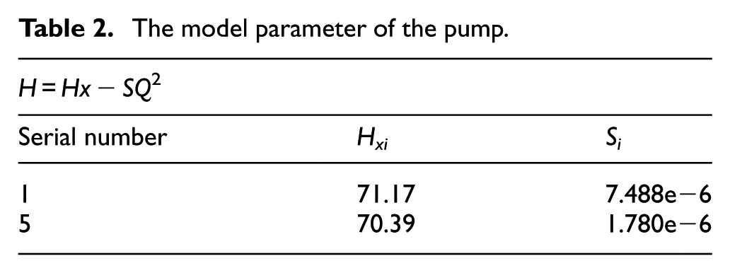
A circulating water pumping station is taken as an example, and the model pump configuration and the characteristics are shown in Tables 1 and 2.
The configuration of the pump station.
The model parameter of the pump.
The basic demand of system can be expressed as in equation (7)

The configuration methods of the variable frequency control for this pump system are shown in Table 3.
Control schemes by VFD.
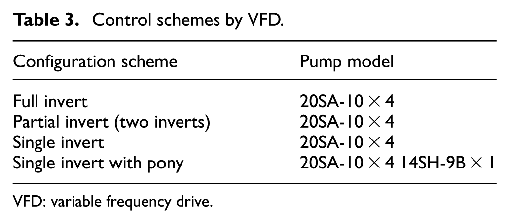
VFD: variable frequency drive.
Based on equations (4)–(6), the efficient operation area for the different configuration scheme can be shown as follows.
As shown in Figure 3, there was still quite large area operation was in need was not contain in single invert configuration. The two operation area was also the main pump working range, so from the viewpoint of the optimizing operation, using this method is not guaranteed that every point can operate in high-efficient area.
Single invert configuration scheme.
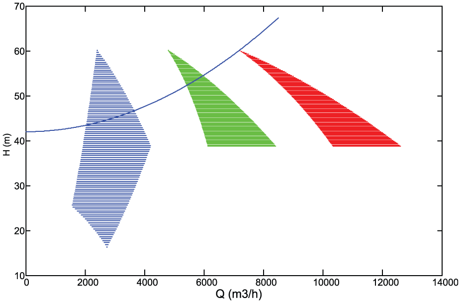
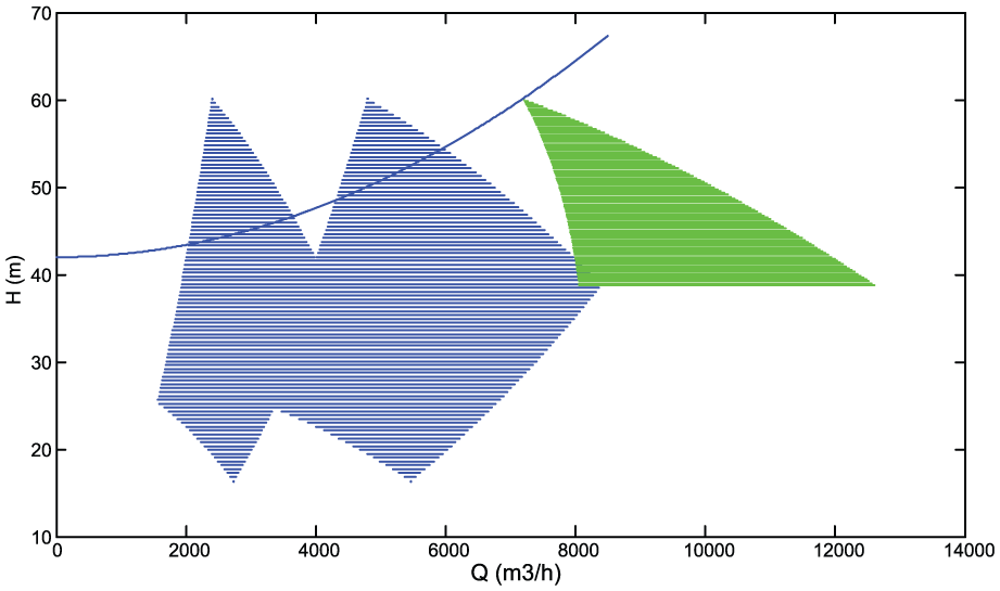
As shown in Figures 3 and 4, the multi-invert method could guarantee the pump operate in high efficient area covered the main work scope of system,so from the point of energy saving, the both configuration method is feasible. Compared with the single invert, the high-efficient area was broadened as shown in Figure 5. But the overlap area of the high-efficient area was significantly increased, which meant the optional optimization scheduling scheme was more. Therefore, the optimized scheme was much more superior.
Partial invert configuration scheme.
Full invert configuration scheme.
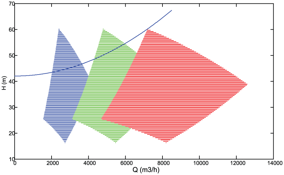
It is remarkable that multi-type pump with single invert control larger pump configuration scheme might achieve good energy-saving effect as shown in Figure 6. The configuration of high-efficient area could even cover more area work than the multi-invert with same-type pump. It can be concluded that multi-type pump is more suitable for the operation requirement with a wide range of flow and head at different time periods than same-type pump configuration. However, the high-efficient overlap area is less, which means the scheduling scheme chosen could be less, and its optimization may be the result of relatively low regulation capability. Even so it is still a cost-effective configuration scheme for the low initial investment.

Single invert with pony pump configuration scheme.
As shown in Figures 7 and 8, if the multi-type pump with single invert control pony pump configuration scheme was adopted, the high-efficient area was particularly small compared with other scheme because of the poor adjustable capacity, but it is also clear that it could achieve high efficiency in fine operation area, hence it could achieve much more energy-saving ability than the other scheme.

Single invert with pony pump(v) configuration scheme.
Single invert with synchronous switch control configurations.
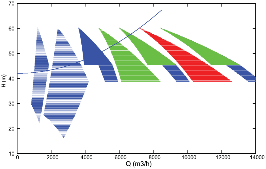
The synchronous switch control was adopted into the multi-type pump with single invert control, and the result is show in Figure 8. The configuration of high-efficient area could almost cover the work area just as the multi-type pump with single invert control larger pump configuration scheme, but the overlap area of the high-efficient area was significantly increased, which means the optional optimization scheduling scheme is more. Therefore, the optimized scheme is much more superior, and the initial investment still almost the same as the single invert with pony pump scheme, so it may be the highest cost-effective way of configuration scheme.
Application realization method of the technology in pumping system
Hardware structure of the control system
When the pump system was equipped with one single invert, and it was needed that the invert could switch between different pumps freely and with real time, then the system must obey the following rules.
First, in accordance with the requirements of the scheduling model, frequency converter can realize the relevant pump controlled. Second, it should overcome the damage caused by the impact current to equipment due to the work frequency conversion power in the switch directly.
To solve these problems, following work should be completed. As shown in Figure 9, this schematic circuit could achieve logical control according to the scheduling model. When the pump M1 was needed to be controlled by invert, the main circuit contactor K2l should first close the suction, and then the invert began to control M1. When the motor M1 was accelerated to the rated speed, the synchronous switch-mode control was implement at the same time by closing bypass operation contactor K11 suction, disconnecting the main circuit contactor K21 after period of time, then the M1 motor was switched to power frequency operation. The frequency converter could be used for other motor control. And when the motor M1 was needed to be stopped, the K11 was disconnected and the k21 was closed at the same time, then the M1 was controlled by frequency converter until the rotation speed almost to zero.

Schematic circuit diagram of the one invert control multi-pumps.
Compared with logical control circuits which could be easily achieved by programmable control relays, circuit contactor, and some controllers, the synchronous switch-mode control between the inverter power and power supply was much more difficult to solve.
As shown in Figure 10, synchronous phase loop control circuit was used to realize the inverter power and power supply synchronous switching. 13

Configuration of the variable frequency synchronous switching system.
This circulating configuration was composed with phase demodulation ring which eliminates the current surge caused by the phase synchronization, the amplitude (voltage) discriminator, frequency detector, and gate circuit.
During work, it is detected that frequency, amplitude, and phase must be consistent with the outside power supply, and then it could implement the switch operation.
Software structure of the control system
Meanwhile, in the existing optimization scheduling model, constant speed pump and variable-speed pump are fixed without switch between them, and the switching technology is not shown in operation, so correlation scheduling model could achieve the switch between variable-speed pump and constant speed pump.11,12
When the whole pumps in the system could be controlled by invert, then every pump has the opportunity to become the variable-speed pump, this would cause the number of the scheduling model as much as the pump quantity which will cause the solving difficulty. As the same-type pump has same characteristics, then the scheduling model would be established according to the number of the pump type. And fortunately, the pump system control by single invert only has two or three kinds of pump in order to facilitate the management, so the scheduling pump was not too complex to solve. The scheduling control model can be shown in Figure 11.

Scheduling model for inverter switching control.
First, the minimum shaft power scheduling models group based on every type pump as variable-speed pump was established. Second solving the model group to obtain the best energy-saving operation state, the best control scheme was chosen according to the degree of difficulty of the control scheme implementation at the requirements of the minimum energy consumption. At last, the control scheme was sent to the control center to implement.
The pump system was chosen as an example: there are two types of pumps, pump A and pump B; the number m; n platform; and the pump power characteristic could be expressed as cubic polynomial function.
The different types of water pump switching model based on the minimum shaft power model can be expressed as


where the J1 is the shaft power model by assuming pump A as variable-speed pump, dji is the cubic polynomial coefficient, and Qi and Hi are the discharge flow and pressure head, respectively, of pump i under certain operating conditions. ki is the conversion coefficient of the speed ratio, c represents the constant speed pump, and v represents the variable-speed pump. Qt and Ht are the flow discharge and the head of requirement of system, and Qmax, Qmin, and kmin are the operation constrain (Figure 1).
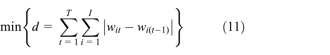
First, the two groups of model were solved and obtained the best energy-saving operation state. And then the pump group was scheduled according to the current operation state and the difficulty of the control action. Measure index model can be expressed as
Application
Profiles the pumping system
The example model is a circulating pump station as shown in Figure 12. It is one of the most important facilities of an alumina plant; it is used for the mother liquor evaporation progress, and it costs almost 17% electricity consumption in the plant. 14

Pump station scene.
There are eight pumps of single stage and double suction in the pumping system, including four hot pumps with same model three in use and one in preparation, four cold pumps with same model three in use and one in preparation. The entire pumps match with 10 kV voltage motor, and the pump group is controlled by throttle in this system.
In this case, the cold pump group is taken as an example, the design parameters of cold water pump is shown as Table 1, and its performance curve is shown in Figure 13.

Pump characteristic.
Based on the historical data of pumping stations, the daily water consumption in some day is shown in Figure 14, and the annual water consumption is shown in Figure 15.

Daily variation curve of whole flow demand.

Annual variation curve of whole flow demand.
For the complex flow demand, the pumping system was controlled by valve; there are about 16% energy-saving potential if operation adjusting method can alter from valve control to speed control through energy audit. 15
Scheme application analysis
According to the analysis of the energy consumption of the pumping system, the equipment variable speed can be used for the energy saving, and for the continuous change of the flow, the frequency converter is especially suitable for this situation. And the schemes can be shown in Table 1.
Then, based on these schemes, the model was constructed, the minimum shaft power is the objective function, the starting factor and speed regulation ratio are taken into consideration and the constraints include the total flow, the equal head, the high-efficiency zones, and the minimum speed regulation ratio. The model is simulated by the genetic algorithm program.16,17 The results are shown in Figure 16.
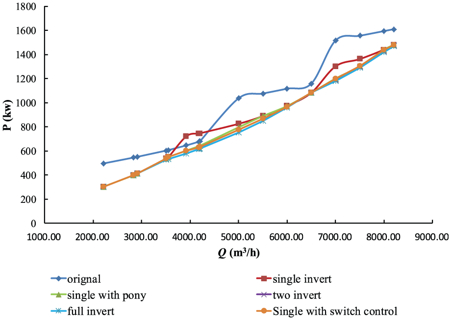
Flow versus total shaft power under different schemes.
It is clear from Figure 16 that, with the full invert, the pumping system can achieve the best effect of the energy saving; the single invert model with low efficiency of pump also could save energy compared with the existing system. However, the purpose of energy-saving reconstruction is not only simple pursuit energy-saving effect, but is also about the overall cost. So economic analysis needs to be done to supply much more rationale and feasible method.
For the economic analysis, the implementation costs and the energy consumption of energy saving need to be calculated within a period of time running under according to the flow demand law of pumping system. So, according to the statistical investigation, 1-year operation condition with annual water law was adopted as shown in Figure 15. Based on Figures 15 and 16, the annual power consumption is shown in Table 4.
The contrast energy consumption of different schemes.

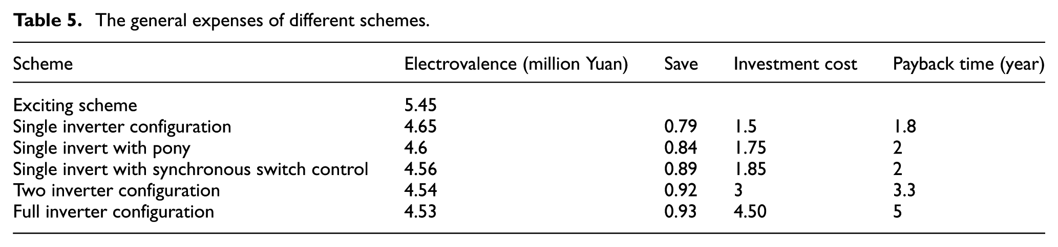
Based on the assumption, the common industry electrovalence is 0.6 Yuan (in RMB) and configuration of the invert with the qualification of 10 kV–710 kW is about 150 million Yuan. Irrespective of transition pump and its supporting high-voltage electromotor, the installation cost is about 25 million Yuan, with configuration switch control system about 0.1 million Yuan. Then the general expenses of these different schemes based on benefit–cost ration are shown in Table 5.
The general expenses of different schemes.
Then, the relationship between time and gain can be obtained as in Figure 17, without compromise on machine.

Relationship between time and gain.
Just as in Figure 17, the single invert configuration scheme is the optimum profit when the working time is less than 5 years, but when the time gets longer than 5 years, the single invert with transition pump configuration is the best gain till the time longer than 20 years, and this may be suitable for this condition, which is recommended. The other two schemes have much more remarkable effect in the energy saving, but they are too long time for the gain.
Among these schemes, the single invert with synchronous switch control is particularly significant; the payback time is almost as same as the single invert with pony pump scheme. But the gain is almost as same as the two inverts scheme; it may be the most high quality and reasonable price scheme.
Conclusion
In this work, a synchronous switch control technology was used in single invert multi-types pump configuration pump system to achieve high-efficiency operation with low investment. As a result of this study, the main conclusion can be drawn as follows:
The high-efficiency operation area of multi-type pump configuration equipped with one invert scheme is suitable for the system to operate over a wide range of flow and heat at different time periods, but the scheduling scheme chosen could be less; its optimization may be the result of a relatively low regulation capability. As a result, a synchronous switch control model was adopted to overcome this defect and to save further energy operation of the pump system.
Synchronous switch control technology is feasible and easily achieved with low investment, the hardware of synchronous switch control could be carried out by a simple logic control circuit which could be easily programmable and a phase discriminator control circuit which could eliminate the impact current. The software of synchronous switch control could be achieved by the minimum shaft power scheduling model group based on every type pump as variable-speed pump which could calculate the optimal operation condition, and the minimum switch number which could ensure the optimal control regulation scheme.
The single invert with synchronous switch control is particularly of high quality and reasonable price. The payback time is almost as same as the single invert with multi-type pump scheme, but the gain is almost as same as the two invert scheme.
Footnotes
Academic Editor: Tatsushi Nishi
Declaration of conflicting interests
The author(s) declared no potential conflicts of interest with respect to the research, authorship, and/or publication of this article.
Funding
The author(s) disclosed receipt of the following financial support for the research, authorship, and/or publication of this article: This project is supported by the National Natural Sciences Foundation of China (Grant no.51409125), the China Postdoctoral Science Foundation (No. 2014M551515), Priority Academic Program Development of Jiangsu Higher Education Institutions, Jiangsu University Fund Assistance (No. 13JDG082), Jiangsu Postdoctoral Research Grants Program (No. 1302026B), and University Natural Science Foundation of Jiangsu Province (No. 14KJB470002).