
Abstract
The backflow vortexes at the suction connection in high-speed centrifugal pumps have negative effect on the flow field. Setting an orifice plate in front of the inducer is able to decrease the negative effect caused by backflow vortexes. The traditional plate is able to partially control the backflow vortexes, but a small part of the vortex is still in the inlet and the inducer. Four new types of orifice plates were created, and the control effects on backflow vortexes were analyzed. The ANSYS-CFX software was used to numerically simulate a high-speed centrifugal pump. The variations of streamline and velocity vectors at the suction connection were analyzed. Meanwhile, the effects of these plates on the impeller pressure and the internal flow field of the inducer were analyzed. Numerically, simulation and experimental data analysis methods were used to compare the head and efficiency of the high-speed pumps. The results show that the C-type orifice plate can improve the backflow vortex, reduce the low-pressure area, and improve the hydraulic performance of the high-speed pump.
Keywords
Introduction
High-speed centrifugal pumps have the characteristics of high speed, high head, and small flow rate. However, because of high speed, they are unstable at small flow rate. This is mainly caused by backflow vortexes at the inlet of the inducer, secondary flow in the impeller, and the jet flow in the impeller channel. The backflow vortexes play a major role because it consumes a large amount of energy and reduces the pump efficiency. Secondly, backflow vortexes will lead to a positive slope rising section on the pump performance curve and the instability of the pump at small flow rates.1–4 Thirdly, the backflow vortex will also generate pressure pulsations, accelerate cavitation, and thus lead to vibration and noise. 5 Si et al. 6 presented an investigation of a single-suction volute-type centrifugal pump and found that the main disturbance in low specific speed centrifugal pump was backflow vortexes of inlet. Backflow vortexes were the major reason for noise and vibration. Ito et al. 7 concluded that backflow vortex led to cavitation phenomenon on inlet of inducer. Kiris et al. 8 did numerically simulation analysis on the low-pressure fuel-turbo pump. The results indicated that backflow vortex was caused by inducer, and there was interaction between backflow and secondary flow. Therefore, the hydraulic performance of the pump could be effectively improved by optimizing the backflow vortex at the inlet of the inducer.
P Cooper et al. 9 proposed that the backflow at the suction connection could be solved by installing a reverse current regulator at the inlet of the inducer. JF Zhang et al. 10 introduced high-pressure liquid at the suction connection to reduce the strength of the backflow vortex, but this will adversely affect the flow field of the pump. Oshima and Toyokura11,12 installed an orifice plate before the inlet of the inducer to weaken the backflow. The effect of orifice was verified in improving the cavitation performance of a centrifugal pump and head of the shut-off condition of the pump. XM Guo et al. 13 simulated and analyzed the GSB-80/300 high-speed pump by orthogonal experiment and determined the best location of the orifice plate, the best orifice plate diameter, and orifice plate thickness.
All the above scholars studied the effect of one circular orifice plate on the hydraulic performance of the pump and did not consider the effects of different types of orifice plates. The effects of four different types of orifice plates on the hydraulic performance of a high-speed centrifugal pump were analyzed, and the best type of orifice plate was selected.
Establishment of high-speed centrifugal pump model
The model of the high-speed centrifugal pump includes five parts: suction connection, inducer, impeller, volute, and discharge section (Figure 1). The flow rate Q=662m3/h, the head H=620m, the speed n=13,000r/min, and the radius of the suction connection R=87mm. Relevant parameters of the inducer and impeller are listed in Table 1.
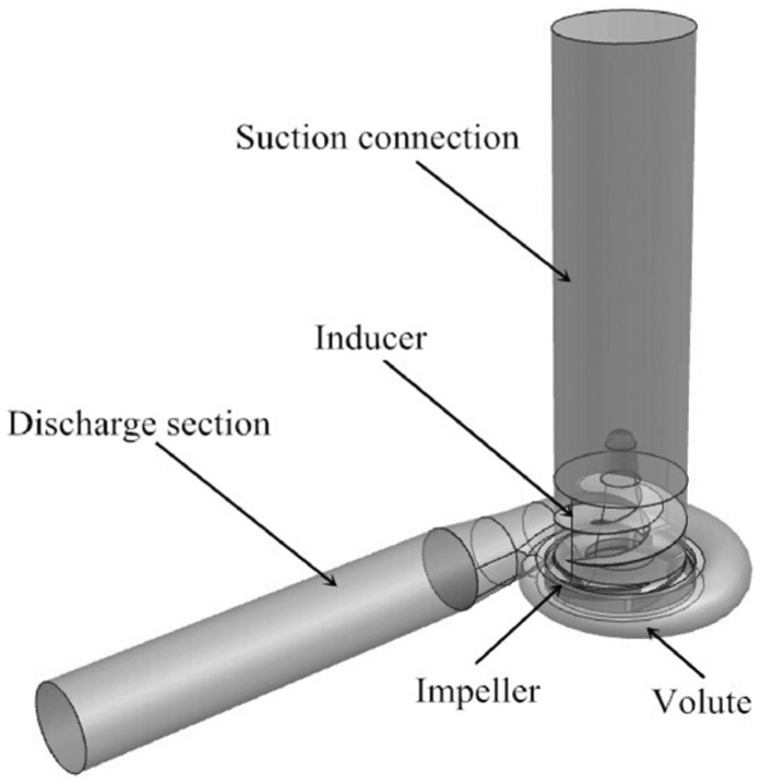
Three-dimensional model of the high-speed pump.
Parameters of inducer and impeller.

XM Guo et al. 13 selected the best dimension of the orifice plate suitable for the GSB-80/300 high-speed pump using the orthogonal test. Three plate thicknesses (10, 15, and 20mm), three plate diameters (1.4R, 1.5R, and 1.6R), and three distances to the inducer inlet (0.92R, 1.03R, and 1.14R) were analyzed. Through numerical simulation, the effects of different plate dimensions to the strength of backflow vortex at the suction connection and the variation of pressure on the inducer were analyzed. The hydraulic efficiencies, head, and axial power of the pump were compared. The optimum values were achieved when plate thickness was 20mm, the plate diameter was 1.5R, and the distance to the inducer inlet was 1.03R (R represents the radius at the suction connection).
Traditional orifice plate is circular, and the plate is placed perpendicular to the wall of the suction connection. This design makes the flow unstable because it lacks a transient area for the flow, and the axial velocity changes abruptly. In order to smooth the flow passing through the plate, an orifice plate with a parabolic cross section was designed. The four different types of orifice plates were as follows: type A orifice plate—ring, type B orifice plate—parabola, type C orifice plate—upper half section as parabola, and type D orifice plate—lower half section as parabola, as shown in Figure 2.

Schematic diagram of the orifice plates: (a) type A orifice plate, (b) type B orifice plate, (c) type C orifice plate, and (d) type D orifice plate.
Model solution and analysis
The ANSYS-ICEM software was used for grid division of the suction connection under different conditions. The unstructured grids were adopted. The total number of grids without the orifice plate, with types A, B, C, and D plates were 9.75million, 9.85million, 9.89million, 10.28million and 9.89million, separately. For the independence analysis of grids, the 10.2million and 9.75million grids were compared, and the head and efficiency of the high-speed pump were stabilized within 1.2% and 1.1%. The grid division is shown in Figure 3.

Schematic diagram of grid division: (a) inducer, (b) impeller, and (c) volute.
The parameters of meshes are listed in Table 2. All qualities of meshes were more than 0.2, and all smallest angles of meshes were more than 18°, which met the calculation requirements (as shown in Table 2). From Figure 4, all of the y plus values of the mesh on the suction surface and pressure surface of the inducer were controlled below 130. The minimum y plus value was 25. The turbulent model was renormalization group (RNG)
Grid parameters.


Distribution of y plus value: (a) suction surface of inducer and (b) pressure surface of inducer.
The ANSYS-CFX software was used to analyze the different types of orifice plates on the high-speed pump. The three-dimensional (3D) Navier–Stokes equations and the RNG
The walls of inducer and impeller were set to rotational boundary, their rotation speed was equal to the rotation speed of pump, and other walls were set to no-slip boundary condition. The inlet boundary condition was set to total pressure, which was equal to the sum of static pressure and dynamic pressure. The outlet boundary condition was set to mass velocity. Pressure term was set to second-order central difference scheme, and other terms were set to second-order windward difference scheme. The residual error was set to 10−4.
Simulation results and analysis
Analysis of the suction section
The main analysis was on small flow rata because the backflow vortex mainly occurred at this flow rate. At 0.6Qd, there was a vortex area in the suction connection. Some liquid flowed back from the inlet of the inducer, which rotated the main stream and formed backflow vortex. 14 The backflow vortex is mainly caused by the uneven force of the liquid flow on the rotating blades. Under the effect of the centrifugal force, there will be a pressure differential between the outer edge and the center of the axis, which leads to backflow. 15
As shown in Figure 5, the influence scope of backflow vortex without the orifice plate is very larger, and the flow at the inlet section is more unstable. After installing the orifice plate, the backflow vortexes were controlled between the orifice plate and the inducer. Even when the liquid flow velocity in this part greatly increased, the influence of the inducer to the internal flow velocity was small.
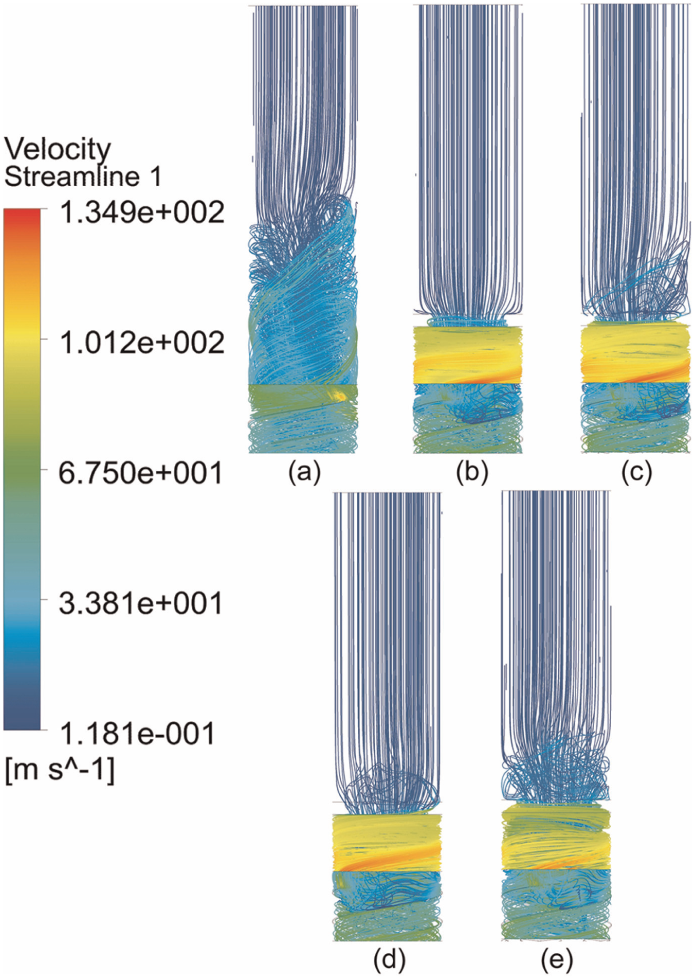
Streamlines of different orifice plates under 0.6Qd conditions: (a) without orifice plate, (b) type A orifice plate, (c) type B orifice plate, (d) Type C orifice plate, and (e) type D orifice plate.
The comparison among different types of orifice plates shows that all four types of orifice plates have positive effect on the backflow. The backflow vortexes rotate circumferentially between the plate and the inducer, which led to the unstable flow on the external wall of the inducer. By observing the streamlines at the inlet section, a small amount of vortexes flow out of the control scope in the types B, C, and D orifice plates. In summary, the orifice plate has certain control effect on the backflow vortexes at small flow rate, but all four types of orifice plates have certain influence on the flow field in the inducer.
The internal flow condition at small flow rate was observed at the inlet section. A plane was taken along the axial direction at inlet section to observe the backflow vortexes. From the internal velocity vector diagram (Figure 6), the backflow vortex flow was more unstable without the orifice plate. Meanwhile, the number of vortexes increased greatly, and the influence scope of vortexes at the inlet section was larger than the design condition.
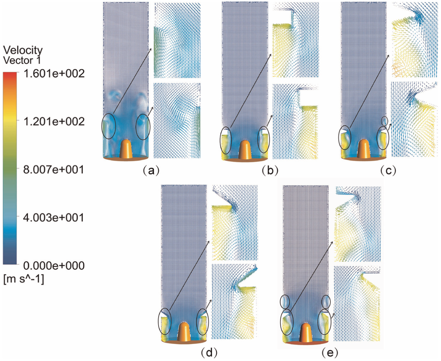
Velocity vectors at the suction connection with different orifice plates: (a) without orifice plate, (b) type A orifice plate, (c) type B orifice plate, (d) type C orifice plate, and (e) type D orifice plate.
After installing the orifice plate, the vortexes were controlled within certain range and were mainly distributed on the circumference of the inlet section. By comparing four types of orifice plates, the effect of controlling backflow vortexes by types A and C orifice plates was better because no vortexes flowed out of the control scope of the orifice plate. A few vortexes flowed out of the orifice plate in the types B and D orifice plates. By observing the liquid flow between the orifice plate and the inducer, the vortexes were controlled by orifice plate near the circumference of the inlet section. The vortex flow near the shaft was smooth, and the vortexes were in circular motion around the axis.
A radial cross section is intercepted at the distance 40mm of the inducer inlet (Figure 7). This plane was set between the orifice plate and the inducer. Without installing the orifice plate, there were more vortexes on the section surrounding the shaft. After installing the orifice plate, the number of vortexes reduced and the liquid flow rotated around the axis. After comparing results of four types of orifice plates, there was a small amount of vortexes on the section of types A, B, and D orifice plates, and the strength of vortexes on the section of type C orifice plate was much weaker than the other three. Therefore, type C orifice plate had an advantage in controlling the radial vortexes at the inlet section.

Cross section of different orifice plates: (a) without orifice plate, (b) type A orifice plate, (c) type B orifice plate, (d) type C orifice plate, and (e) type D orifice plate.
The effects of four different types of orifice plates on the backflow vortex were compared when the flow pattern in the inlet section was under the small flow rate. The four type orifice plates had a good control effect on the backflow vortex, but there were still some undesirable vortexes in the flow field. The control effects of backflow vortexes by the type C orifice plate were better than other three types of orifice plates.
Analysis of inducer
The backflow vortex created a small low-pressure zone on the front edge at the inlet of the blade, which increased the chance of cavitation. The variation of static pressures on the suction and pressure surfaces of the inducer with different types of orifice plates was observed (as shown in Figure 8). On the suction surface, the pressure increased from the inlet to the outlet, which indicated that the inducer was a pressure-increasing device. The pressure increased from the hub to the rim on the pressure surface. Without installing the orifice plate, some low-pressure zones were observed on the front edge at the inlet of the blade. The area of low-pressure zones was larger than that at the design condition. The above phenomenon means that the size of the backflow vortex would affect the pressure distribution on the inducer.
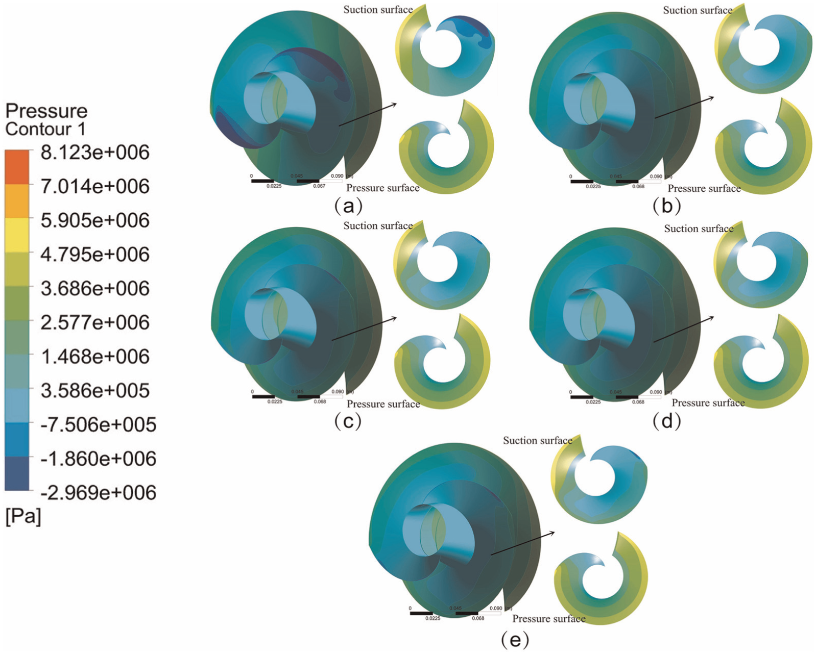
Pressure distribution on the inducer: (a) without orifice plate, (b) type A orifice plate, (c) type B orifice plate, (d) type C orifice plate, and (e) type D orifice plate.
After installing the orifice plate, the area of low-pressure zones reduces obviously. This indicates that the orifice plate controls the backflow vortexes and reduces the area of low-pressure zones at the inlet. The low-pressure zone decreased obviously while using the type C orifice plate. There was an extremely small area of low-pressure zones while using the type A orifice plate. There were still some low-pressure zones while using the types B and D orifice plates.
The backflow vortex mainly occurred on the periphery of the inducer inlet. A plane perpendicular to the axial plane of the inducer was taken to observe the variations of flow field in the inducer. This design was used to analyze the effects of different types of orifice plates to the flow field in the inducer (Figure 9).

The cross section of the inducer.
From the velocity vector diagram in the inducer, there are backflow vortexes on the periphery of the inducer inlet, and some vortexes near the hub in the flow field without the orifice plate. After installing the orifice plate, the backflow vortexes at the inlet of the inducer were reduced obviously. The control effect of backflow vortexes at the inlet by the type A orifice plate was obvious, but there were some vortexes in the flow field and at the outlet of the inducer. The velocity vector diagram of types B and D orifice plates were similar to the result of type A. The C-type orifice control backflow vortex had a better effect. There were no undesirable vortexes in the flow field, so that the liquid flow was smooth and changes uniformly (Figure 10).

Velocity vectors at the cross section of the inducer: (a) without orifice plate, (b) type A orifice plate, (c) type B orifice plate, (d) type C orifice plate, and (e) type D orifice plate.
In order to further analyze the influence of the orifice plate on the cavitation of the inducer, rotation cavitation flow numerical calculation under cavitation state on the 0.6Qd condition is done. As shown in Figure 11, in the case of without the orifice plate, the volume fraction of the suction surface of the inducer was full of three-quarters of the impeller. Cavitation has been very serious. After installing the orifice plate, the volume fraction is obviously reduced, and the cavitation performance of the high-speed centrifugal pump can be improved by the orifice plate. By comparing four types of orifice plates, the volume fraction of the type A orifice plate decreases, but there is a large area of cavitation. The types B and D orifice plates control the effect of cavitation better than the A type orifice plate. The effect of the volume fraction of the type C orifice plate is the best. The volume fraction is mainly distributed in the rim, and there is little distribution in the hub.

Volume fraction distribution on the suction surface of the inducer: (a) without orifice plate, (b) type A orifice plate, (c) type B orifice plate, (d) type C orifice plate, and (e) type D orifice plate.
The distribution of gas volume fraction of pressure surface was observed (as shown in Figure 12). Without installing the orifice plate, a small fraction of the volume fraction is relatively large on the front edge at the inlet of the blade. After installing the orifice plate, the area of cavitation reduces obviously. By comparing four types of orifice plates, the types A, B and D orifice plate also has a small part of the volume fraction at the tip of the blade. However, there is no cavitation erosion on the pressure surface of the type C orifice plate.

Volume fraction distribution on the pressure surface of the inducer: (a) without orifice plate, (b) type A orifice plate, (c) type B orifice plate, (d) type C orifice plate, and (e) type D orifice plate.
In conclusion, all four types of orifice plates are capable to control the low-pressure zone and volume fraction on the front edge at the inlet of the blade under the small flow rate. By comparison, the A- and C-type orifice plates have a better effect on the low-pressure zone and volume fraction of the inducer. After comparing the influence of the flow field inside the inducer, types C is better than other three types of orifice plates.
Analysis of high-speed pump’s performance
After installing different types of orifice plates, the head and efficiency of the high-speed pump were calculated. The calculation formulas are as follows


The head decreased gradually with the flow rate increasing (Figure 13). The head changed when orifice plate adds to the system. The head of type C orifice plate was 7m larger than type A orifice plate at 0.6Qd. The head of type C orifice plate was 13m larger than without orifice plate at 0.6Qd. At the design conditions, the head of type A, C orifice plate, and without orifice plate were more than type B, D orifice plate. The head of type B orifice plate and type D orifice plate was declining obviously. At the large flow rate condition, the head of without orifice plate was more than the installing orifice plate, which indicates orifice plate could decrease head of high-speed pump


Curve of flow-head.
The calculated volumetric efficiency was 97%, the mechanical loss was 94%, and bearing and packing material loss was 2%. Therefore, the total simulated efficiency of the high-speed pump was 62.2% without the orifice plate. From the efficiency curve, it can be concluded that the efficiency increases and then decreases with the flow rate. The highest efficiency is at the design operating point. All four types of orifice plates cause increase in the efficiency while installing orifice plate. At the design operating point, the efficiency nearly increases 5% while installing types A and C orifice plates and increases 4% while installing types B and D orifice plates. At low flow rates, the efficiency also increases obviously after installing the orifice plate. When the flow rate was larger than 1.2Qd, the efficiencies are basically the same, which indicates that the orifice plate has little effect on large flow rates (Figure 14).

Curve of flow-efficiency.
Experimental results and analysis
This experiment uses the closed experimental platform, which is equipped with a cavitation tank, a buffer tank, and an experimental pump. In order to guarantee the experimental accuracy in the test, you need to set the valve and high-precision flowmeter. To set the valve and high-precision flowmeter, measure the flow and pressure changes of the high-speed pump. Open the test pump, adjusting the electric control valve of the test pipeline outlet, so that the pump in a certain flow is in stable operation for a period of time. Adjust the electric control valve, so that the flow control is in the 0.3Qd–1.3Qd range. Record the pressure and flow changes under five different conditions. And, the head and efficiency of the high-speed pump are calculated under different conditions.
After comparing the results from the numerical simulation, the type C orifice plate has a best effect in all aspects. Therefore, only the A-type and C-type orifice plates are selected for the experimental demonstration. The efficiency and head of the high-speed pump are tested in the lab, results of which are used to compare to the numerical simulation results. The basic experimental tests show that the error of efficiency of all three cases was controlled within 5%, and the head variation was within 10m. This data will be further proving the creditability of the simulation results. The new orifice plate can improve the hydraulic performance of the high-speed pump.
After comparing the experimental data of type A orifice plate and type C orifice plate, both head and efficiency curve experiment data are lower than the simulated data. This may be caused by the neglecting of some losses in the numerically simulated model and the losses in the pipeline and the manufacturing error. On the whole, the variation trends of numerical simulation and experiments are basically the same. Meanwhile, the error was also controlled within a certain range. Above results indicate that the numerically simulated data are creditable (Figure 15 and Table 3).
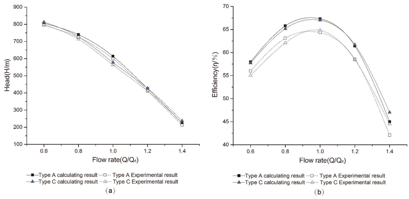
Comparison between calculating value and experimental value: (a) curve of flow-head and (b) curve of flow-efficiency.
Comparison between experimental results and numerical calculation results at the design operating point.

CFD: computational fluid dynamics.
Conclusion
Under the small flow rate, the control effects of backflow vortexes are compared by analyzing the streamlines and velocity vectors at the suction connection when installing different types of orifice plates. Although the type A orifice plate has certain control effect on backflow vortexes, there is a small amount of axial and radial vortexes in the inlet section. The small vortex has a bad influence on the flow field of the inducer. The effect of types C is better than other three types of orifice plates. There are no undesirable vortexes in the flow field, and the flow is smooth and changes uniformly.
After comparing the pressure and the internal flow field of the inducer, the inducer and the backflow vortex have a significant improvement after adding four kinds of orifice plate for the low-pressure zone and cavitation. The types C and A orifice plates have better effect on controlling the low-pressure zone and volume fraction of the inducer inlet.
The experimental data are compared with the numerical simulation results. Due to the existing of losses and human factors during the experimental process, the experimental results have some errors, but all the errors are within the reasonable scope. This indicates that the simulation results are creditable, and the effect of orifice plate in controlling the backflow vortexes is proved. In the design conditions, the efficiency of type A orifice plate is nearly equal to the efficiency of type C orifice plate. At the large flow rate condition, the type C orifice plate has a better effect on improving the efficiency.
In conclusion, the advantage of type C orifice plate is higher than traditional type A orifice plate in all respects through comprehensive comparison and analysis for suction connection, inducer, and hydraulic performance of high-speed pump.
Footnotes
Appendix 1
Academic Editor: Roslinda Nazar
Declaration of conflicting interests
The author(s) declared no potential conflicts of interest with respect to the research, authorship, and/or publication of this article.
Funding
The author(s) disclosed receipt of the following financial support for the research, authorship, and/or publication of this article: This study was financially supported by the State Key Program of National Natural Science of China (grant no. 51279172), the Open Research Fund Program Provincial Key Laboratory of Fluid Machinery of China (grant no. szjj2015-037), and the Innovation Fund Program of Graduate Students in Xihua University (grant no. ycjj2015044).