
Abstract
Closed-loop systems of an electro-hydraulic servo system including position, acceleration, and force closed-loop systems and their closed-loop transfer functions based on parameter model are adaptive identified using a recursive extended least-squares algorithm. The position and force closed-loop tracking controllers are designed by a proportional–integral–derivative controller and are tuned by the position and force step signals. The acceleration closed-loop tracking controller is designed by a three-variable controller and the three states include position, velocity, and acceleration. Experimental results of the estimated position, acceleration, and force closed-loop transfer functions are performed on an actual electro-hydraulic servo system using xPC rapid prototyping technology, which clearly demonstrate the benefit of the adaptive identification method.
Keywords
Introduction
A new structural diagram of electro-hydraulic servo system (EHSS) is shown in Figure 1, including position, acceleration, and force closed-loop servo systems, with advantages such as powerful density, large forces, and high tracking accuracy.1–3 The EHSS consists of a force loading system, a shaking table, a test specimen, eight exciters, two reaction walls and the portal frame, and so on. In order to achieve the vibration environment simulation, a test specimen is installed on the shaking table, which is connected to hydraulic exciters by hinge supports. The hydraulic exciters provide power to drive the shaking table. The EHSS has been employed in many position, vibration, and force tests to evaluate original structural performances and their potential problems under actual working environment.4–6 However, the acceleration/force loading tracking accuracy with traditional methods on the EHSS is limited because of system nonlinearities including servo valve dynamics, spherical joint clearance, and frictions.7,8

Structural diagram of the EHSS.
In order to improve the tracking performance, the position, acceleration, and force closed-loop systems are designed to optimize the control methods of the EHSS. A three-variable controller (TVC), including position, velocity, and acceleration, is commonly employed for acceleration tracking control, 9 especially in E-Defense shaking table. 10 In this article, the TVC is employed to control the acceleration closed-loop system, which can extend the frequency bandwidth and improve stability of the acceleration closed-loop control system. A proportional–integral–derivative (PID) controller is employed to implement force tracking control.
After the position, acceleration, and force closed-loop systems have been established, their closed-loop transfer functions should be identified for further designing an advanced controller, such as feed-forward inverse model compensation based on the estimated transfer functions including the position, 11 acceleration,6,9 and force closed-loop systems.6,12 In order to obtain an accurate feed-forward inverse model and improve tracking accuracy of some reference signals, it is important to ensure identification accuracy of the electro-hydraulic system transfer function. The currently widely used method is to identify the closed-loop system transfer function first, and then, their inverse transfer function is obtained by offline design method.6,9 System identification is an important approach to model dynamical systems, which includes non-parameter identification based on Welch’s periodogram method, 13 a parameter identification algorithm based on recursive least-squares algorithm14,15 and a recursive extended least-squares (RELS) algorithm,6,9 a coefficient-level mapping method, 16 a modal-based structural identification algorithm, 17 and a state-space model algorithm, 18 and so on. The identified model of non-parameter identification is the frequency characteristic, but the parameter identification can obtain model parameters, and it is difficult to design the inverse model using the non-parameter model. Liu and Lu 19 developed a least-squares algorithm–based iterative identification method for a class of multi-rate sampled-data systems. Bao et al. 20 proposed a least-squares algorithm–based iterative parameter estimation algorithm for multi-variable controlled autoregressive moving average (ARMA) model with finite measurement data. A standard least-squares identification algorithm was employed to identify the system parameters without considering the nonlinear dynamics characteristics. 21
The RELS algorithm is an effective method to estimate the closed-loop system dynamics based on parameter model. 22 Comparing with the least-squares algorithm, the RELS algorithm has a faster convergence performance and higher accuracy. In a study by Tang et al., 23 the RELS algorithm was applied to identify the electro-hydraulic system parameters, which was employed to design an inverse controller. In a study by He and Zhang, 24 an RELS algorithm was proposed to identify parameters of the ARMA model of network utilization. In study by Rout and Subudhi, 25 system parameters of an autonomous underwater vehicle were identified using the RELS algorithm.
With comparison of the traditional fixed controller, the adaptive controller has strong adaptability characteristics, which can automatically adjust the controller parameters as the change of system performance. Chen et al. 26 proposed a µ-synthesis control strategy to improve the tracking performance of the linear motor driven stages with high-frequency dynamics for an adaptive robust control technique. In a study by Sun et al., 27 a constrained adaptive controller was designed to improve the vibration isolation performance for vehicle active suspension systems. Yao et al. 28 proposed an adaptive backstepping controller with a friction compensator to improve the tracking accuracy with parametric uncertainties and nonlinear frictions. An adaptive repetitive controller was employed to compensate the periodic modeling uncertainties for motion control of the hydraulic servomechanisms. 29
In order to improve closed-loop transfer function identification accuracy, the RELS algorithm is combined with adaptive control to identify the closed-loop transfer function of the EHSS, which is used to design the feed-forward inverse model. Experiments are performed on an actual experimental EHSS to verify the benefit of the identification method, and the experimental results demonstrate that the position, acceleration, and force closed-loop transfer functions based on parameter model can effectively be identified using the RELS algorithm. This article is organized as follows. Section “Dynamic model of the EHSS” describes the investigated EHSS and its nonlinear mathematical model. Section “Position, acceleration, and force controllers of the EHSS” discusses the position, acceleration, and force controllers of the EHSS. In section “Closed-loop transfer function identification algorithm,” the RELS algorithm is employed to identify the closed-loop system transfer functions. Experiments are conducted and their results are discussed to analyze the effectiveness of the identification algorithm in section “Experiment study.” Conclusions are drawn in section “Conclusion.”
Dynamic model of the EHSS
Figure 1 shows the structure of the EHSS, which is comprised of eight hydraulic actuators controlled by eight servo valves. The model of the servo valve can be expressed as follows

where Q is the flow of the servo valve,

where


where

where

where
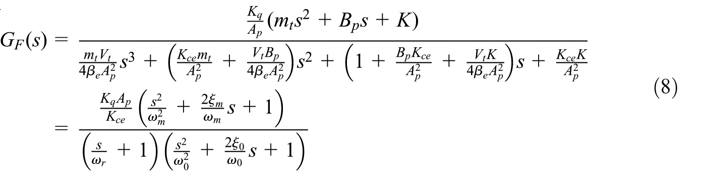
With combination of equations (2), (5), and (6), an open-loop dynamic model from the drive signal to the displacement of the hydraulic actuator without an external force with Laplace transformation can be expressed as follows

where

Block diagram of the displacement controller system.
According to equations (2), (5), and (6), the transfer function from the servo valve displacement to the actuator generated force can be written and simplified as follows
where

Block diagram of the force controller system.
In order to evaluate the established model accuracy, the frequency response of the simulation and experimental results is presented in Figure 4, and the main simulation parameters are listed in Table 1. It can be seen that the mathematical model is closed to the actual experimental system.

Frequency characteristics of dynamic model and experimental results: (a) magnitude frequency characteristics and (b) phase frequency characteristics.
Main parameters of the simulation model.

Position, acceleration, and force controllers of the EHSS
Position controller
With consideration of the established dynamic model in equation (8), the position controller can be designed as Figure 5. The reference displacement signal

where
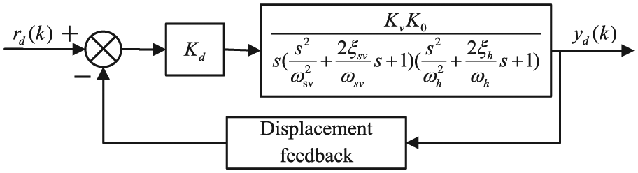
Block diagram of the closed-loop position system.
Acceleration controller
The TVC is an essential controller for electro-hydraulic shaking tables with 2-degree-of-freedom control structure including a feedback controller and a feed-forward controller. A block diagram of the TVC is given in Figure 6, where the design of the TVC is based on the position closed-loop system. The TVC directly represents the displacement and acceleration of the EHSS measured by a linear variable differential transformer (LVDT) and an accelerometer, respectively, while the velocity feedback signal is synthesized using a low-pass filter with the displacement and a high pass-filter with the acceleration. It can be seen that the acceleration reference signal

Block diagram of the acceleration controller.
From Figure 6, it is obvious that the transfer function of the acceleration generator can be deduced as follows

where

where

where

Force controller
Figure 7 is a diagram of the force controller, where the PID controller

Block diagram of the force controller.
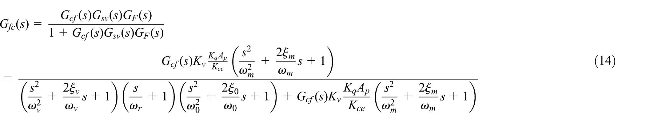
As can be easily inferred from Figure 7, the transfer function of the force controller can be deduced as follows
Closed-loop transfer function identification algorithm
The closed-loop transfer function of the EHSS must be identified. The RELS algorithm is employed to identify the transfer function and improve closed-loop transfer function identification accuracy. The principle of frequency response function estimation based on the RELS algorithm is shown in Figure 8.

Block diagram of the RELS algorithm: (a) RELS algorithm for the EHSS and (b) schematic representation of the RELS algorithm.
In Figure 8,

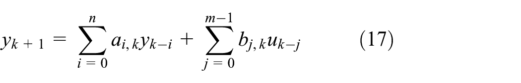
When the controlled object models are unknown, a general experience model is commonly used to describe the adaptive control strategy and it can be expressed as follows

where y is the output signal, u is the input signal,
If the base functions
Because of the good convergence and simple calculation, the RELS algorithm is widely employed in real-time processing. However, there are noise and interference signals in the control system inevitably, and the identification of the noise model should be taken into consideration. Therefore, equation (17) is rewritten as follows

where

where
Similarly, the RELS algorithm can be expressed as follows6,9


During the process of identification, the system parameter
Experiment study
Experimental setup
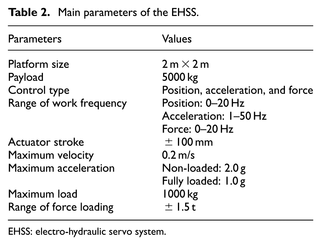
In this section, an experimental EHSS is shown in Figure 9, and Figure 10 shows how to implement the position, velocity, and acceleration controllers and their closed-loop transfer function identification. The experimental system consists of a platform, 8 actuating cylinders, a reaction base, 8 Moog two-stage servo valves (G761-3004), 16 spherical hinges, and some relative sensors including 8 LVDTs, 8 accelerometers, and 16 pressure transducers. Eight servo valves manufactured by Moog Company with a 38 L/min flow capacity at 7 MPa supply pressure control the cylinder. The actuators providing the driving forces have a 70mm bore and 50mm rod. The LVDTs are attached to the eight hydraulic actuators to measure the displacement and eight force sensors fixed between the hydraulic actuator for force measured and a spherical hinge to acquire the present force loading. Eight PCB accelerometers mounted on the drive rod of the eight cylinders are installed to obtain the acceleration information. The main parameters are listed in Table 2.

Experimental system.
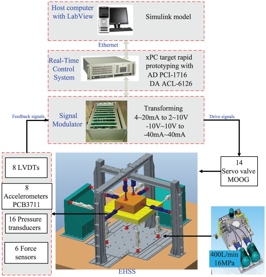
Control scheme of the EHSS.
Main parameters of the EHSS.
EHSS: electro-hydraulic servo system.
The hardware architecture of the control system is processed on xPC target based on MATLAB/Simulink rapid prototyping. The programs of the proposed controller and data acquisition are designed with MATLAB/Simulink and compiled by Microsoft Visual Studio.NET on the host PC and then is downloaded to the target for implementation. As can be seen from Figure 11, the control hardware for the EHSS includes an Advantech IPC-610 controller, a PCI-1716, an ACL-6126, a host PC, and others. The acceleration and displacement signals are first converted and amplified by the conditioning module to −10 to +10 V signals and then are collected by the 16-bit Advantech A/D card PCI-1716 on the target computer. The control analog output signal completed by the D/A acquisition board ACL-6126 converts the digital signal into the analog signal by a signal modular and sends it to the servo valve for the control of hydraulic actuators.
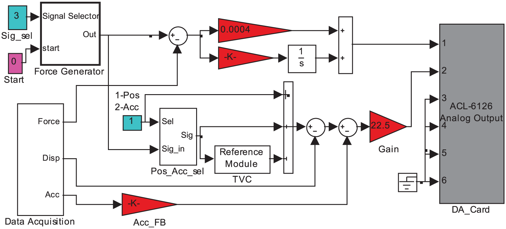
Experimental MATLAB/Simulink model for the EHSS.
Step experimental results
The parameters of above-mentioned identification algorithm are adjusted with a step reference signal. As shown in Figure 12, these are experimental results of the position, acceleration, and force with their reference signals and experimental signals output, respectively, and the tuned experimental parameters are listed in Table 3. It can be obviously found that the performance of identification model using the step signal satisfies the actual experimental setup. So, the experiment of the tracking performance can be conducted.

Experimental results with a step signal: (a) position control, (b) acceleration control, and (c) force control.
Tuned experimental parameters.

Experimental results of the position closed-loop transfer function
After the process of the position controller, the output signal collected could be used for system identification with the RELS algorithm. And, the reference signal is a random displacement signal with the magnitude of 0.5 g and the frequency range of 2–100 Hz; hence, the discrete transfer function of the position control system model can be expressed as follows

As shown in Figure 13, the estimated system model well matches the experimental result calculated by the RELS algorithm with a Hanning window and during the interest frequency for the magnitude and phase properties. Therefore, the conclusion can be drawn that the time and frequency response of the experiment is satisfied.

Experimental results of the position closed-loop control system: (a) time response, (b) magnitude frequency characteristics, and (c) phase frequency characteristics.
Experimental results of the acceleration closed-loop transfer function
A random acceleration signal with the magnitude of 0.5 g and the frequency range of 2–100 Hz is employed in the acceleration control system, and the actual measured acceleration output signal is collected for system identification. The discrete transfer function of the TVC-controlled system model employing the above-mentioned identification algorithm can be expressed as follows

The time and frequency response of the experimental and identified EHSS is shown in Figure 14. From Figure 14, it can be obviously seen that the estimated system model well matches the experimental results calculated by the RELS algorithm with a Hanning window and during the interest frequency for the magnitude and phase properties. So, accuracy of the identified system model is reliable.

Experimental results of the acceleration closed-loop control system: (a) time response, (b) magnitude frequency characteristics, and (c) phase frequency characteristics.
Experiment results of the force closed-loop transfer function
After the EHSS is well-tuned by the PID controller, a sweep-frequency force signal with the magnitude of 24.25–25.75 kg and the frequency range of 0–20 Hz is applied to the PID controlled system, and the output signal from the experiment is collected for system identification. The discrete transfer function of the PID controlled system model can be expressed as follows

To effectively estimate accuracy of the identified system model, the time and frequency response of the experimental and identified EHSS is depicted in Figure 15. The curve of the estimated system model well matches the experimental result calculated by the RELS algorithm with a Hanning window and during the interest frequency for the magnitude and phase properties. Therefore, it can be concluded that the RELS algorithm is well to identify the force closed-loop system.

Experimental results of the force closed-loop control system: (a) time response, (b) magnitude frequency characteristics, and (c) phase frequency characteristics.
Conclusion
A dynamic model of the EHSS is established, and the position, acceleration, and force closed-loop controllers of the EHSS are designed, respectively. The acceleration closed-loop controller is designed by the TVC, and the position and force closed-loop controllers are designed by the PID controller. Closed-loop system transfer functions of the EHSS, including the position, acceleration, and force closed-loop system, are adaptive identified using the RELS algorithm. The experiments are conducted on hardware-in-the-loop-simulation platform using xPC rapid prototyping to verify the practical feasibility of the designed controllers and identification algorithm. In order to verify the benefit of the identification method, experiments are performed on an actual experimental EHSS, and the experimental results demonstrate that the position, acceleration, and force closed-loop transfer functions based on parameter model can effectively be identified using the RELS algorithm.
Footnotes
Academic Editor: Nasim Ullah
Declaration of conflicting interests
The author(s) declared no potential conflicts of interest with respect to the research, authorship, and/or publication of this article.
Funding
The author(s) disclosed receipt of the following financial support for the research, authorship, and/or publication of this article: This research was supported by the National Natural Science Foundation of China (grant number 51575511) and Program for Changjiang Scholars and Innovative Research Team in University (No. IRT_16R68).