
Abstract
The characteristics of electro-hydraulic servo system of full-hydraulic leveler are high speed, large inertia, high frequency response, and multi-degree of freedom. In order to improve the degree of automation of full-hydraulic leveler and achieve the simultaneous control between position and pressure, the position–pressure cooperative control strategy is presented in the article. In the working process, the dynamic working pressure signal of the hydraulic cylinder is turned into a real-time position signal by the pressure–position conversion gain and then compensates the converted signal into the position closed loop. Meanwhile, the pressure signal of the rear cavity of the hydraulic cylinder is fed back to the input of the proportional relief valve at the pump source, and then the system work pressure changes quickly according to the different thickness. In this article, the mathematical model of position–pressure cooperative control of hydraulic straightening machine is established. The simulation results in AMESim software verify the correctness of the control strategy. Finally, the feasibility and practicability of the control strategy are verified by the field prototype of 11-roller full-hydraulic leveler. The control strategy provides the theoretical basis for designing the electro-hydraulic servo system.
Keywords
Introduction
The production level and quality of heavy and medium plate represent the developmental level of a national steel industry. Heavy and medium plate has been paid more and more attention due to its high added value.1,2 The full-hydraulic leveler is indispensable for heavy and medium plate production. It is an important straightening equipment which can eliminate wave shape defects and residual stress, meanwhile ensuring flatness of the steel plate. Hydraulic servo system, as a key component of the full-hydraulic leveler, has great theoretical research value and realistic directive significance. 3
The characteristics of hydraulic system of full-hydraulic leveler are high speed, large inertia, high frequency response, and multiple degrees of freedom. In the process of straightening heavy and medium plate, the traditional control method mainly focuses on position closed loop which can guarantee the control and track of hydraulic cylinder displacement,4,5 but unable to achieve online real-time control of pressure. Meanwhile, the traditional hydraulic system pump source employs electromagnetic spill valve to adjust the working pressure which has overflow losses and energy waste during the plate-straightening process. In the work process, system pressure has a great fluctuation due to processing errors and mechanical vibration, once if the full-hydraulic leveler straightening ability and overload protection response is not timely, which may lead to frame pull-off and bring irreparable harm to equipment and personal safety. 6 Simple position closed loop is unable to meet the needs of modern straightening process, which not only need to guarantee high-precision control of position but also need to achieve accurate control of pressure.
Over the past several decades, some researchers have theoretically investigated the control strategy for position control of hydraulic servo system, pressure control of hydraulic servo system, and position–pressure compound control of hydraulic servo system. The German SMS company has proposed the control principle of the position outer loop and the pressure inner loop for the jumping control in the hot rolling mill. However, the coupled relationship between two closed-loop controllers and the matching relationship between parameters have not been clearly given. 7 KK Ahn and QT Dinh 8 have improved the control characteristics of hydraulic system by online optimization of the Mamdani proportional–integral–derivative (PID) fuzzy controller which has been applied to the electro-hydraulic control system. JA Ferreira et al. 9 proposed a new control method where position control and pressure control, which, respectively, have an independent gain, aim at the hybrid fuzzy logic controller of force and position. However, smooth transition was unable to achieve between different control models. Z Song 10 proposed a feedforward tracking compensation method for electro-hydraulic servo position–pressure compound control method in order to improve the control performance of forging equipment. GR Chen et al. 11 proposed a new method for adaptive robust controller design by designing a control state-space expression with a virtual control quantity, meanwhile combining a state observer to overcome the shortcomings of the classical adaptive robust control method. L Quan et al. 12 researched the mechanism of series control and parallel control aiming at position and force compound control of electro-hydraulic servo system, meanwhile proposed a combination method of series control and parallel control which can achieve shockless conversion between position control and pressure control. HJ Zhang 13 proposed a fuzzy intelligent, self-learning straightening model for full-hydraulic leveler electro-hydraulic servo control system, which further improved roll gap value and fuzzy compensatory value. S Mobayen 14 proposed a new dynamic PID sliding mode control technique for a class of uncertain nonlinear systems. I Hassanzadeh 15 researched the particle swarm optimization (PSO) which is a robust stochastic evolutionary computation method based on the movement of swarms looking for the most fertile feeding location. S Mobayen and D Baleanu 16 presented a novel global sliding mode control technique for the stabilization of a class of uncertain and nonlinear dynamic systems with perturbation.
To date, there have been a few studies highlighting the position closed-loop control, pressure closed-loop control, dynamic PID sliding mode control, and position–pressure compound control. However, there is limited research studying position–pressure cooperative control and rapid online change of pressure according to different load. Generally, more studies need to be conducted to research aim at the hydraulic servo system of large flow, heavy load, high precision, and multi-degree of freedom in order to achieve the simultaneous reasonable online high-precision control between position and pressure in one process.
This article proposes a full-hydraulic leveler position–pressure cooperative control strategy as shown in Figure 1. In the process of straightening, dynamic working pressure signal of hydraulic cylinder is turned into a real-time position signal by the pressure–position conversion gain, and then compensates the converted signal into position closed loop. At the same time, pressure signal of the rear cavity of hydraulic cylinder is fed back to the input of proportional relief valve at the pump source, and then the system work pressure is changed quickly according to the plate of different thickness. The size of the pressure is controlled by proportional relief valve which not only ensures the control precision of position but also improves the overload protection capacity and the control performance of the system of the full-hydraulic leveler, reduces the overflow loss of the hydraulic system, and improves the automation.

Schematic diagram of position–pressure cooperative control of full-hydraulic leveler.
Mathematical model of position–pressure cooperative control of full-hydraulic leveler
Flow equation of proportional servo valve
The core of the electro-hydraulic servo system of full-hydraulic straightening machine is the asymmetric valve control asymmetric cylinder which includes proportional servo valve and asymmetric hydraulic cylinder as shown in Figure 2.17,18 It is necessary to deduce the flow equation of the proportional servo valve, the continuity equation of the hydraulic cylinder, and the force balance equation of the hydraulic cylinder, in order to deduce position–pressure cooperative control mathematical model of full-hydraulic leveler.
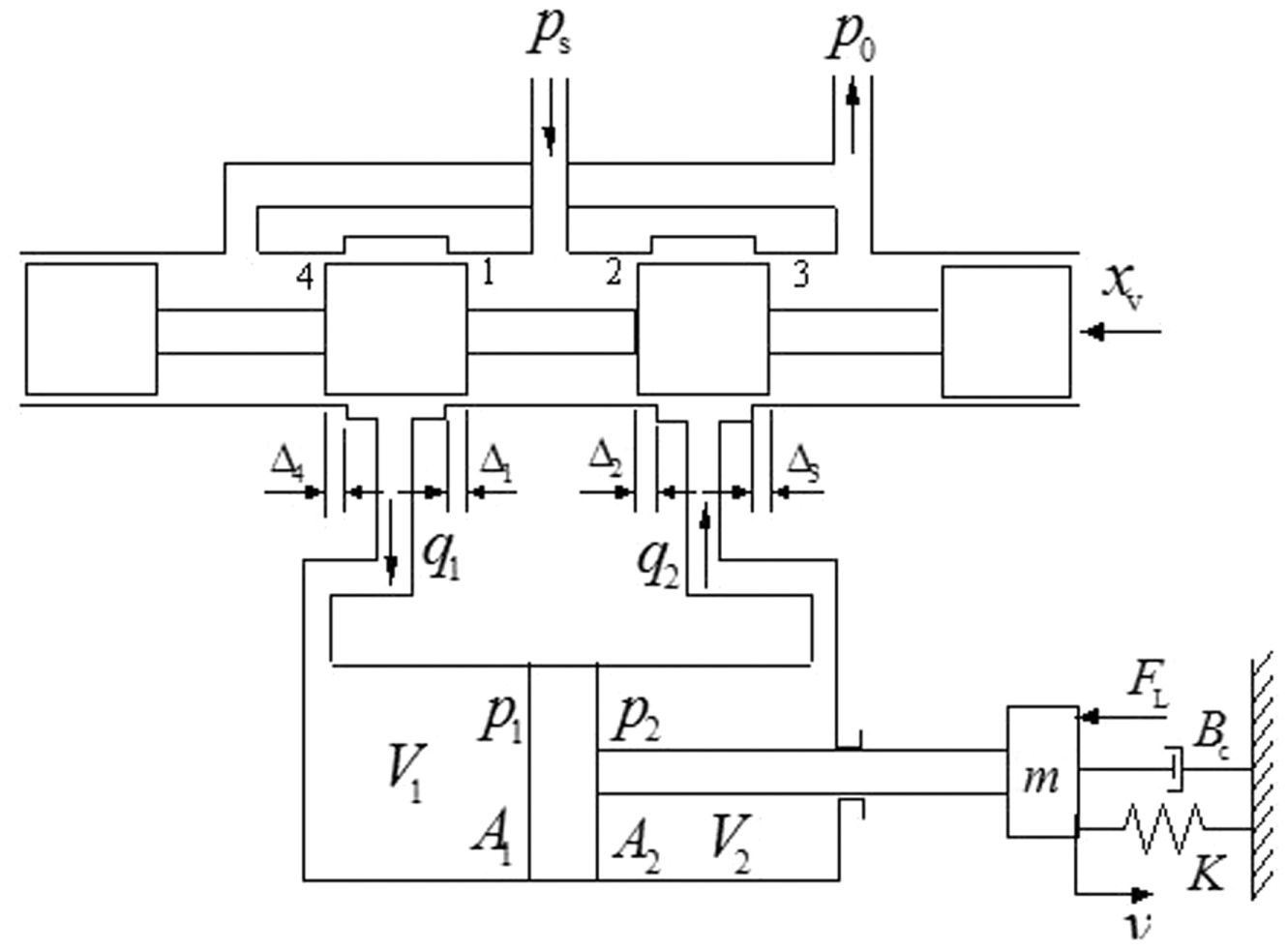
Schematic diagram of asymmetric valve control asymmetric cylinder.
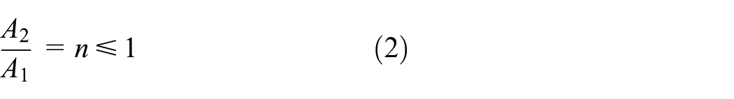
In order to solve the pressure shock caused by complex load changes and hydraulic cylinder commutation, the method of asymmetric proportional servo valve control non-symmetric hydraulic cylinder is adopted. The asymmetric valve refers to the area gradient of the hydraulic oil in and out of the throttling window into a certain proportion

where
For the cylinder
where
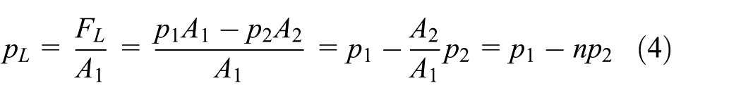
When the electro-hydraulic servo system of full-hydraulic leveler achieves a dynamic equilibrium stage, the balance equation of force is as follows

where
The direction of the piston rod of the servo cylinder stretched out is the positive direction. Here,
The output power of the hydraulic cylinder is

Then, the load flow is

When the hydraulic cylinder moves to the right, that is to say
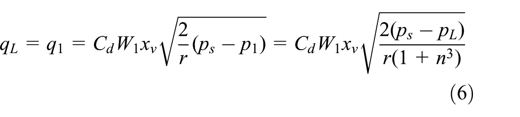
which is the linearized equation at the balance point and meanwhile omits the incremental sign; then, the flow equation of the spool valve is obtained as follows

where
Flow continuity equation of hydraulic cylinder
In order to deduce the flow continuity equation of the hydraulic cylinder, the ideal conditions assumed in this article are as follows: the loss of pipelines and the influence of piping dynamics can be neglected, the volume elastic modulus of the oil and the temperature can be regarded as constant, and the internal and external leakage of the hydraulic cylinder can be regarded as laminar flow. The simplified continuity equation of the hydraulic cylinder can be obtained as shown in equation (8)19,20

where
Equilibrium equation between servo cylinder and load
The dynamic characteristics of hydraulic power component are affected by load characteristics. Load force generally includes an inertial force, viscous drag, elastic force, and any external load force. 21
The equilibrium equation of the cylinder and load is

where
By using Laplace transform to formulas (7)–(9), we can get


We get the main transfer function of non-symmetrical valve controls of asymmetric hydraulic cylinder as follows

Pressure–position conversion gain model
In this article, the definition of the pressure–position conversion gain is represented by

where
Mathematical model of other control elements
Mathematical model of servo amplifier
The frequency of the servo amplifier is generally much higher than the natural frequency of the servo valve. 22 Mathematical model of the servo amplifier is described by the proportional element.
The following formula can be used
where
Mathematical model of pressure sensor
Pressure sensor has advantages of small volume, good stability, and high sensitivity, which converts the collected system pressure signal into a proportional feedback current signal
where
Mathematical model of displacement sensor
Displacement sensor response frequency is far greater than the response frequency of the whole system, so its transfer function is approximated with the proportional element
where
Mathematical model of proportional relief valve
For the convenience of system analysis and modeling, a typical second-order system is usually chosen to approximate proportional relief valve transfer function as shown in the following equation

It is assumed that a constant signal of the proportional servo valve is given. Pressure equation of proportional relief valve is shown in the following equation

where
By using Laplace transform in formula (19), we can get

Proportional servo valve has the inhibition role for hydraulic oil in the hydraulic circuit, known as the liquid resistance. In order to simplify the calculation process, the relationship between the flow rate of the proportional servo valve and the pressure drop can be expressed by the following equation

where
Assuming that the position of the hydraulic cylinder piston rod remains fixed during the working process, equation (8) can be changed as follows

By using Laplace transform in equations (19), (21), and (22), we get the proportional servo valve liquid resistance transfer function as follows

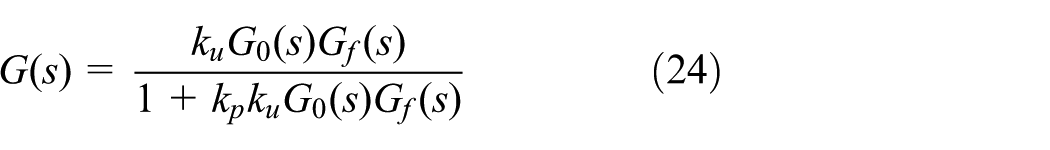
The transfer function of the pressure closed loop of the proportional relief valve is as follows
Mathematical model of position–pressure cooperative control of full-hydraulic leveler
According to the system composition, the main transfer function equation (13) of asymmetric valve control asymmetric hydraulic cylinder, pressure–position conversion gain conversion model equation (14), pressure sensor transfer function equation (16), displacement sensor transfer function equation (17), and the closed-loop transfer function equation (24) of the proportion relief valve constitute, we can get the position–pressure cooperative control mathematical model of full-hydraulic leveler as shown in Figure 3.

Mathematical model of position–pressure cooperative control.
Simulation verification
Electro-hydraulic servo system control model of full-hydraulic leveler is composed of hydraulic oil, servo valves, displacement sensors, pressure sensors, hydraulic cylinders, motors, proportional relief valves, and other components. The position closed-loop control model and the position–pressure cooperative control model of full-hydraulic leveler obtained in the AMESim software are, respectively, shown in Figures 4 and 5. The parameters of the hydraulic components in the simulation model are shown in Table 1.
Set the appropriate PID simulation parameters, where the external load is a constant load that

Position closed-loop control model.

Position–pressure cooperative control model.
Specific parameters of hydraulic system.


Unit step response curve of position closed-loop control.

Unit step response curve of position–pressure collaborative control.
The simulation results of position closed loop show when the piston rod reaches the target displacement (1 mm), stability is very good, steady-state error is zero, the oscillation frequency of the system is zero, system rise time is 0.068 s, and response time is 0.13 s, as shown in Figure 6. Rise time of the unit step response curve of position–pressure cooperative control is 0.05 s and response time is 0.1 s. The response speed has increased 0.3 s and the response time has increased 0.018 s, as shown in Figure 7.
Partial magnification of unit step response curve shows that the position curve fluctuates within 0.01 and 0.03 mm when the pressure step changes (0.3, 0.6, 0.9, and 1.2 s). The converted position signal is compensated into the position closed-loop process which may lead to small location fluctuations due to the instantaneous pressure change, as shown in Figure 8.
2. Set the parameters in order to simulate the pressure rapid response to external load changes. Set

Partial magnification curve of unit step response.

Pressure step response curve of position–pressure collaborative control.
Pressure step response curve of position–pressure cooperative control shows that the rise time from 0 to 14 MPa is 0.04 s and the response time is about 0.2 s, the rise time from 14 to 20 MPa is 0.01 s and the response time is about 0.015 s, the rise time from 20 to 26 MPa is 0.01 s and the response time is about 0.015 s, and the actual pressure can reach the target pressure quickly and stably. It shows that the control strategy can respond quickly to the change of target pressure, and the pressure of rear cavity of hydraulic cylinder is controlled reasonably, as shown in Figure 9.
Partial magnification of pressure step response curve shows that pressure curve will fluctuate within a very small range when reaches the target value. There was a 1-MPa error between the pressure response value and the target value as the pressure difference of the servo valve is 1 MPa, as shown in Figure 10. The position closed loop is unable to achieve the quick pressure response.
3. Simulation of position–pressure cooperative control for four-cylinder synchronization

Partial magnification curve of pressure step response.
The full-hydraulic leveler is one of the typical four-cylinder synchronous motion metallurgical equipments. In this article, one master and three slaves method is used to verify the feasibility of the position–pressure cooperative control. The four-cylinder synchronization model of full-hydraulic leveler position–pressure cooperative control is shown in Figure 11.
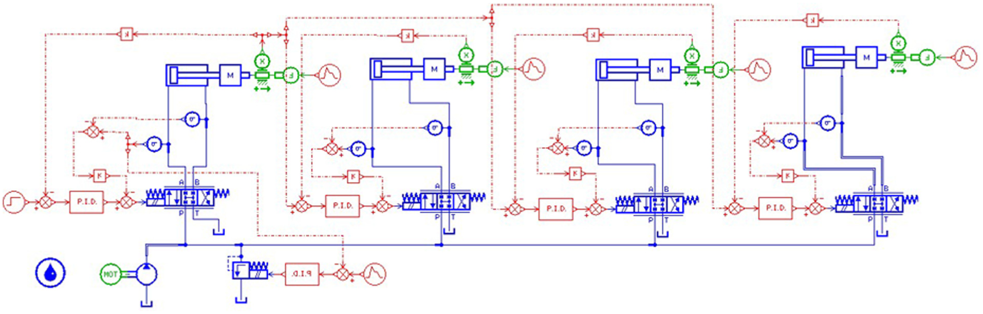
Four-cylinder synchronization model of position–pressure collaborative control.
Set the 1# hydraulic cylinder as the main control cylinder, and the 2#, 3#, and 4# hydraulic cylinders as the slave cylinders. Adjust the appropriate PID parameters; the simulation results of four-cylinder synchronization of position–pressure cooperative control are shown in Figure 12.

Position step response curve of position–pressure cooperative control of four-cylinder synchronization.
The position step response curve of the position–pressure cooperative control for four-cylinder synchronization shows that the position step response curve can respond to reach the target value quickly and stably. However, the position step response time of the 2#, 3#, and 4# cylinders lag behind 0.012–0.015 s relative to the 1# hydraulic cylinder, and then quickly respond to the target value, as shown in Figure 12.
Partial magnification of the position step response curve shows that there are instantaneous fluctuations near the target value when the pressure step changes (0.3, 0.6, 0.9, and 1.2 s). The maximum position fluctuation of the 1# hydraulic cylinder is 0.01 mm, 2# and 3# hydraulic cylinders is 0.02 mm, and the 4# hydraulic cylinder is 0.035 mm, as shown in Figure 13. The converted position signal is compensated into the position closed-loop process which may lead to small location fluctuations due to the instantaneous pressure change.

Partial magnification curve of unit step response curve of four-cylinder synchronization.
The pressure step response curve of four-cylinder synchronization shows that the pressure step response curve can respond quickly to reach the target value and response fast and stably to meet the system requirements. However, the position response curves of the 2#, 3#, and 4# cylinders relative to the 1# hydraulic cylinder have hysteresis about 0.012–0.015 s and then respond quickly to the target value, as shown in Figure 14.
Pressure step response curve of four-cylinder synchronization.
Partial amplification of pressure step response of four-cylinder synchronization shows that the pressure curve will fluctuate in a small range when reaching the target value. Therefore, the stability of the system is very good. Between the pressure response value and the target value, there will be a 1-MPa error because the pressure difference of the servo valve is 1 MPa, and the pipeline loss is negligible, as shown in Figure 15.

Partial amplification curve of pressure step response of four-cylinder synchronization.
The position response curve and the pressure response curve present hysteresis mainly due to the coupling characteristics of the four-cylinder synchronous system of the full-hydraulic leveler. Before the control model is not decoupled, the movements of the four cylinders are prone to disorder, resulting in the 2#, 3#, and 4# slave hydraulic cylinders lag behind the 1# main hydraulic cylinder.
Experimental studies
In order to verify the correctness, feasibility, and practicability of the position–pressure cooperative control strategy of the full-hydraulic leveler proposed in this article, the experiment is carried out in two parts. First, verify that the correctness of pressure signal is compensated into the position closed loop at small valve control cylinder test bench in the laboratory, as shown in Figure 16. Then, the feasibility of the four-cylinder synchronization is verified by the field prototype of 11-roller full-hydraulic leveler, as shown in Figure 18.
Small valve control cylinder test bench.
Experiment on a small valve control cylinder test bench
The step response curves of two different methods show that piston rod reaches the target displacement (60 mm) need about 10 s at the condition of position closed loop, and the average speed is 6 mm/s which is close to the simulation result (7.69 mm/s). When the pressure signal is compensated into the position closed loop by the pressure–position conversion gain, the piston rod reaches the target displacement (60 mm) need about 6.5 s, and the average speed is 9.2 mm/s which is close to the simulation results (10 mm/s), as shown in Figure 17.

Step response curves of two different methods.

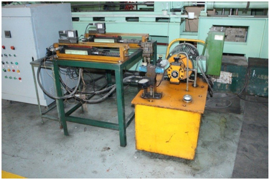
Eleven-roller full-hydraulic leveler in the field.
Experiment on 11-roller full-hydraulic straightening machine
As the laboratory test bench spring stiffness is small, the working process of full-hydraulic leveler is actually four-cylinder synchronous motion. In order to more clearly verify the feasibility, the position–pressure cooperative control four-cylinder synchronous motion experiments are validated by the field prototype of 11-roller full-hydraulic leveler. The asymmetric proportional servo valve model is 4WRDE16-125 L-5X/6L24 K9/M, the cylinder model is φ580/420-350, the displacement sensor model is RHM0420MD701S2 G1102, the pressure sensor model is HDA3840-A-400-000, the displacement of the hydraulic pump is 250 mL/r, the straightening speed is 0.5–1 m/s, and the plate length is 15–20 m.
The position–pressure cooperative control four-cylinder synchronous motion experiments of full-hydraulic leveler are as follows: (1) verify the pressure quick response and four-cylinder synchronization at the condition of no-load; (2) verify the stability of the four-cylinder synchronization by straightening 18-mm-thick Q235B and 24-mm-thick Q235B.
Verify the pressure quick response and four-cylinder synchronization at the condition of no-load. (a) Set the pressure target values as 17 and 22 MPa and verify the pressure quick response at the condition of no-load. Pressure signals of four hydraulic cylinders are collected by pressure sensors. The pressure rapid response curves are shown in Figures 19 and 20.

Pressure rapid response curve of four-cylinder synchronous motion.

Partial amplification curve of pressure rapid response curve of four-cylinder synchronous motion.
Pressure rapid response curve of four-cylinder synchronization presents that the pressure curve can quickly respond to reach the target pressure values (17 and 22 MPa) through the position–pressure cooperative control strategy. Pressure from 0 MPa respond to the target pressure of 17 MPa which requires 0.1 s of the rear cavity of the 1#, 2#, 3#, and 4# hydraulic cylinders. However, the pressure response time of the 2#, 3#, and 4# cylinders lag behind 0.01–0.012 s relative to the 1# hydraulic cylinder and then quickly respond to the target value, as shown in Figure 19.
Partial amplification of pressure rapid response of four-cylinder synchronization presents that the system pressure response time is 0.4 s from 17 MPa to the target pressure of 22 MPa. The pressure curve presents a short shock and overshoots due to the momentary mutation occurred at 6 s and then quickly responds to the target pressure value and remains fluctuating within a small range. The overshoot of the 1#, 2#, 3#, and 4# hydraulic cylinders is 2.1%, 2.3%, 4.5%, and 3.5%, respectively, as shown in Figure 20.
(b) Assuming that displacement target value of four-cylinder synchronous motion is 20 mm, and the experiment is verified at the condition of no-load. Position signals of four hydraulic cylinders are collected by displacement sensors. The position response curves are shown in Figures 21 and 22.

Displacement response curve of four-cylinder synchronous motion.
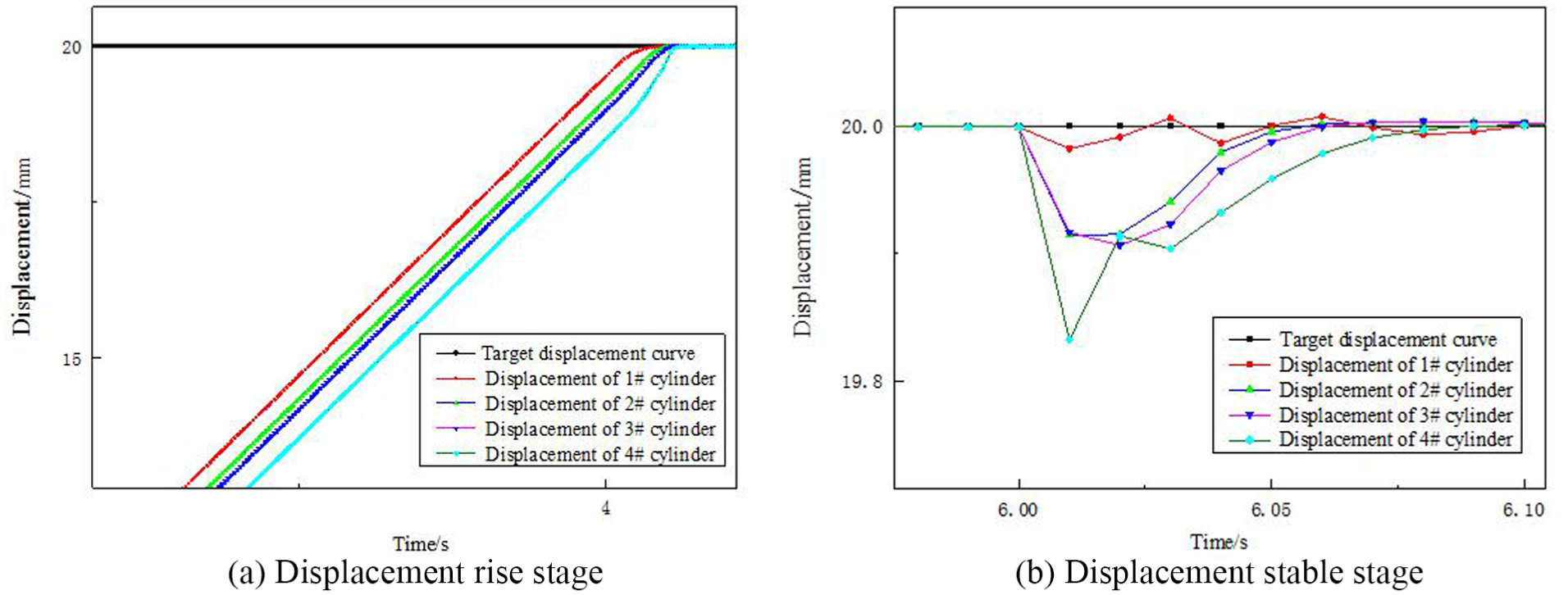
Partial amplification curve of four-cylinder synchronous motion.
Displacement response curve of four-cylinder synchronization presents that the four hydraulic cylinders can respond to the target displacement (20 mm) through the position–pressure cooperative control strategy. The parameter P of proportion servo valve is small (P = 1.2) in order to ensure the safety and reliability during experimental process, so the response speed is relatively slow, as shown in Figure 21. However, the displacement response time of the 2#, 3#, and 4# cylinders lag behind 0.01–0.015 s relative to the 1# hydraulic cylinder, and then quickly responds to the target value and remains fluctuating within a small range, as shown in Figure 22.
Partial magnification of four-cylinder synchronization curve shows that the position curve fluctuates within 0.05 and 0.17 mm when the pressure step changes (6 s). The maximum position fluctuation of the 1#, 2#, 3#, and 4# hydraulic cylinders is 0.17, 0.11, 0.12, and 0.05 mm, respectively, as shown in Figure 22. The converted position signal is compensated into the position closed-loop process which may lead to small location fluctuations due to the instantaneous pressure change.
2. Experiment the stability of four-cylinder synchronization by straightening 18-mm-thick Q235B and 24-mm-thick Q235B.
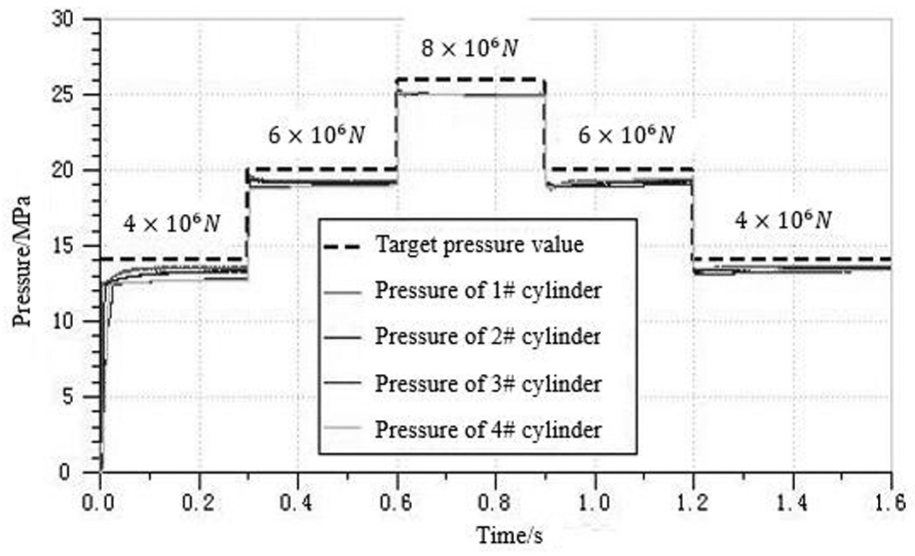
In order to verify the feasibility of four-cylinder synchronous motion of full-hydraulic leveler position–pressure cooperative control strategy, two types of thickness (18-mm-thick Q235B and 24-mm-thick Q235B) are straightened. The position signals of four hydraulic cylinders are collected by position sensor. The actual roll gap curves of steel plate straightening are obtained, as shown in Figures 23 and 24.

Actual roll gap of straightening 18-mm-thick plate.

Actual roll gap of straightening 24-mm-thick plate.
The experimental results show that the four-cylinder synchronization is good when straightening plates with different thickness at the condition of position–pressure cooperative control. The maximum deviation between the actual roll gap and the target roll gap is within 0.15 mm, while the average deviation is controlled within 0.078 mm, which can meet the actual production needs.
Discussion
In order to solve the problem that position and pressure of full-hydraulic leveler cannot be controlled simultaneously during the plate-straightening process, the position–pressure cooperative control strategy has been put forward in this article. The mathematical model of the position–pressure cooperative control of full-hydraulic leveler is established. Both simulation results and field experiment data prove the correctness, feasibility, practicability, and stability of the control strategy.
The simulation and experimental results show that whether position step curve or pressure response curve of full-hydraulic leveler position–pressure cooperative control strategy can quickly respond to the target value changes, and the errors can been controlled within the allowable range. The position response speed increased 3.2 mm/s, and the pressure achieved a rapid change. Through the field data, it is found that the maximum deviation between the actual roll gap and the target roll gap is within 0.15 mm, while the average deviation is controlled within 0.078 mm, which can meet the actual production needs.
Conclusion
The realization of full-hydraulic leveler position–pressure cooperative control strategy has certainly guiding significance for researching and designing of other electro-hydraulic servo systems. The method presented in this article cannot achieve optimal control and multi-cylinder decoupling control. In the future study, an iterative algorithm of optimal control design strategy aiming at the full-hydraulic leveler position–pressure coordination control strategy will be researched, which will have a low computational complexity and a fast convergence rate. The future work needs to also combine the intelligent control, the adaptive fuzzy control, and the multi-degree-of-freedom feedback decoupling control theory for improving the control accuracy, response speed, and intelligence level of full-hydraulic leveler electro-hydraulic servo system.
Footnotes
Acknowledgements
D.H. and T.W. were responsible for building a model and performed the experiment; J.W. and Z.R. were responsible for the acquisition and analysis of experimental data; and X.G. drafted the article and supervised the research.
Handling Editor: Dumitru Baleanu
Declaration of conflicting interests
The author(s) declared no potential conflicts of interest with respect to the research, authorship, and/or publication of this article.
Funding
The author(s) disclosed receipt of the following financial support for the research, authorship, and/or publication of this article: This paper was supported by NSFC-Shanxi Coal Base Low Carbon Mutual Funds (grant no. U1710254), Shanxi Province Science and Technology Major Project (grant no. MC2016-01), Natural Science Foundation of Shanxi Province (grant no. 201701D121078), Provincial Fund for Young Scholars (grant nos 201701D221140 and 201701D221143), and the Initial Funding of Doctor Research of Taiyuan University of Technology (grant no. 1205-04020203).