
Abstract
A wheel/track mobile robot with a one-way tail rod is studied. First, from the analysis of its performance, the mechanical structure of the wheel/track mobile robot is designed and the hardware composition of its control system is given. Second, based on the analysis of its variable structure movement process, the variable structure model of wheel/track mobile robot is established using the geometry analysis method. Third, two kinds of analysis are proposed. One is analysis of the wheel movement on flat ground. Another is track obstacle-crossing kinematics of the robot, in which the conditions for its stairs-climbing are determined. Then, the dynamical model of stairs-climbing is established either in wheel mode or in track mode using the classical mechanics analysis on the robot during the stairs-climbing process. Through simulation and experiments, the effectiveness of the model and the evaluation method of the wheel/track mobile robot in stairs-climbing are verified, which can provide design and analysis foundations for the wheel/track mobile robot.
Introduction
Over the past few decades, there have been numerous studies on the mobile robots since they can help human to perform dangerous missions in complex and unpredictable environments, such as rescue, anti-terrorism, removing explosive, planetary exploration, and so on. In these cases, since robots must move in very complicated and irregular environments, such as high steps, stairs, narrow space, or unstable ground, it is usually required that robots should be portable and have mobility on climbing slope, surrounding high obstacle, or moving on uneven ground.
Generally, transformable track robots and hybrid robots are two principal types which are applied in various environments. For example, typical transformable track robots include CALEB-2, 1 VSTR, 2 ROBHAZ-DT, 3 single-tracked, 4 VGTV, 5 and NEZA-I, 6 and typical hybrid mechanism robots include AZIMUT 7 and the miniature wheel–track–leg mobile robot. 8 At the beginning, typical hybrid mechanism robots are generally equipped with not only wheels but also tracks, and this complex superimposed mechanism significantly increases the complexity of their structures, weights, and volumes. Also, the tracks of these robots keep winding around the sprocket all the time. As a result, lots of energy is usually consumed by these typical hybrid mechanism robots.
To solve the problem, a new type of transformable wheel–track robot is being researched.9–11 On flat grounds, it can walk in wheel mode to save energy and has a relatively high velocity; while on rough roads or stairs, it can transfer into track mode, which is shown in Figure 1: a wheel–track robot only consists of one simplified and compact coupling reconstruction mechanism, which is capable of transferring between walking in wheel mode and track mode, combining both advantages of a wheel robot and a track robot. In this case, this wheel–track robot is a good choice especially in a comprehensive case that most of the time the ground is flat but there are sometimes rough grounds, steps, or stairs. With this integrated function, wheel–track robots are not only applied to missions such as anti-terrorism and fire rescue, but also can be used as a stair-climbing chair to help the disabled.10,12–16

Although a transformable wheel–track robot is an idea choice for its integrated functions, sometimes complex walking environments require higher function which has better stability. A novel transformable wheel–track robot which is much lighter, more simplified, and compact has been developed by introducing a tail rod whose winding will coordinate the center of gravity of the wheel/track robot to improve the stability of the robot movement. Besides, referring to previous researches,17,18 the dynamic obstacle crossing in different climbing modes is analyzed in this article. Section “Variable structure device design of the robot’ of this article discusses the variable structure device design of the robot using geometry analysis; In section “Retractable track,” the operation of the retractable track is described in detail. Sections ‘The mechanical structure of the robot” and “The control system of the robot” briefly introduce the mechanism structure and the control system of the robot; section “Analysis of the robot in stairs-climbing” analyses the motion abilities of different modes of the robot. Finally, our experiment results and conclusions are, respectively, offered in sections “Experimental and discussion” and “Conclusion.”
Variable structure device design of the robot
In order to coordinate the attitude of the wheel/track variable structure robot, the two sides of the driven rod maintain the symmetry of the motion in the track expansion/contraction process as far as possible, using a double four-bar linkage transformation mechanism. If triangles

Graphic design of four-bar linkage variable structure device.
The location of the hinge point D
The bigger ratio between track segment length and wheel segment length of wheel/track robot, the better the robot can get obstacle-crossing performance under the same wheel diameter. In this circumstance, there are higher requirements of the scalability of the crawler, and the length between the two teeth to decorate a circular arc is restricted. Through taking into account the operating conditions and other factors of the robot, determining the diameter R of walking wheel and diameter r of swing arm wheel, and ensuring the length of the track when the crawler is fully expanded is 1.5 times of the circumference of the wheel, the equation can be concluded to determine the length of the swing arm L according to Figure 1, which can be listed as follows
In the above formula, assuming the big wheel radius
The scope of

Through the fullexpand function of mathematica, simplifying the above linear equation as follows: if
Considering the possibility of installing pressure belt pulleys at
The determination of
,
, and the angle
During the opening process, the variable structure mechanism needs to overcome considerable complex resistances including track spring tension forces
Force analysis on the point
During the progress the track unfolds, the link rod
Force analysis on the point
First, the point

There is some value for r which make
Determine the position of
Draw a circle with A as the center and R as the radius. The thick dotted line depicts the state of wheel mode. When truckles drawback, the distance from

Otherwise, double four-bar linkage cannot completely draw back into gear rings. In the above inequality,
Determine the value of
through plotting method
The hinge point on another side is the intersection
The angle of active rod is selected by geometric construction method
The coarser dotted line indicates the state of the swing arm wheel, if
Simulation calculation
The robot adopts double four-bar linkage transformation mechanism as shown in Figure 3. The simulation model of the double four-bar linkage is shown in Figure 4. In the process of the variable structure expansion, the force is complex and related to the terrain and so on. The force variation of the driven connecting rod is simulated by loading horizontal and vertical forces which are approximately measured by measuring track tension force experiment in both left and right swing arm wheels. Through the simulation analysis, it is found that the maximum force is not in the expansion, but in about 3 s as shown in Figure 5, but actual load forces in the end (gravity and the tension of the spring) are more than the load in 3 s moment, namely, in 3 s moment load should be less than the simulation of loading, and required torque of simulation load at the end is less than this force value in 3 s moment. In consideration of the above factors, the worm gear motor includes rated voltage 24 V, rated torque 12 N m, and rated speed of 7 r/min.

Double four-bar linkage transformation mechanism.

Simulation model of the double four-bar linkage.

Simulation results of double four-bar linkage.
Retractable track
In track mode, the track is much longer than that in wheel mode, so the track should be made of a material with a low elastic modulus, but the mesh between track teeth and the gear ring requires a kind of high elastic modulus material to avoid slipping. In consequence, a retractable track is assembled by the rubber timing belt shown in Figure 6, which is as long as the perimeter of the triangle outline of the opened double four-bar linkage mechanism. The track is made of the rubber timing belt and spring. Dividing the timing belt into appropriate segments, a spring is mounted inside to expand and contract the belt and guide transmission, and some aluminum blocks are fixed outside as outer teeth of the track. In the track mode, the up and down track teeth mesh with the gear rings to transmit large force, while in the wheel mode, track teeth mesh with gear rings in the form of circular.

Retractable track.
The mechanical structure of the robot
The robot mainly consists of four parts as shown in Figure 7: the variable structure device, the walking device, the box body, and the tail rod. The variable structure device is achieved by a double four-bar linkage mechanism. The worm gear motors with double output shafts on both sides of the robot, respectively, drive the two sets of the main driving shafts on both left and right sides of the wheel/track transformation mechanism. The worm gear mechanism is self-locking, one side of the double output shaft is used to connect the main driving shaft of the wheel/track transformation mechanism, and the other side is to install the potentiometer to complete the angle detection. The walking wheel device is mainly composed of an internal and external gear ring devices, which is driven by a decelerated direct current (DC) motor. In order to make the robot’s structure more compact, the output torque of the walking motor speed reducer is transmitted to the gear shaft through a pair of gears so that the walking motor on both sides can be arranged in a staggered way. The two gears of the gear shaft are separately geared with the inner teeth of the two gears of the walking wheel device; as a result, the inner and outer gear rings are able to complete synchronous rotation. The tail rod motor can drive one-way wheel rod to swing to adjust the centroid of the robot.

Robot mechanical structure.
The control system of the robot
PC program, remote control program, and the robot body program are the three fundamental parts of the robot program development. PC program is based on VC++ implementation, which enables the display of the robot postures and the sending of the control instructions. Remote control program is achieved through the STM32 + wireless serial port conversion, through which the instructions are sent to make it more convenient for the user to operate the robot body through the handle. While the control program of the robot body is achieved through the STM32 + ucos way that is displayed in Figure 8 including eight sub-processes, and the communication process 1 and the communication process 2 are separately applied to accept the remote control instructions and exchange PC data. The external sensor is used to obtain the information from wall barriers, and it can also be transmitted to the PC display via the communication process 1. The attitude detection process detects the robot attitude by gyroscope, accelerometer, and the encoder and delivers the display to PC through the communication process 1, which works as a reference for the user to operate a robot. The action process of the driving wheels on left and right hands controls the walking wheel action of the robot. Variable structure motor control process is used to control the expansion and contraction of the track, while the tail rod motor control process is used to control the motor action of the tail rod.

The software block diagram of control system.
Analysis of the robot in stairs-climbing
Analysis of motion in wheel mode
When the road is in good condition, the robot can move in wheel mode, the wheel can keep a circular shape and rotate quickly to implement the fast moving of the robot. At this time, the robot will be simplified to two driving wheels, two universal wheels, and one box body. A simplified model of the robot is shown in Figure 9. Establishing coordinate system in Figure 9, in which XOY is the plane coordinate system that is fixed on the ground, xPy is the relative coordinate system which goes through the middle point P of the two driving wheels.

Simplified robot model.
Taking P point as the motion reference point, the linear velocity and the angular velocity of the robot as v and

Supposing the centroid of the robot M is similar to the geometric center of the box body, the distance from the particle to point P is d, and then the coordinates of the centroid are as follows

Taking the derivative of equation (6) and combining equation (5), the equation of centroid motion of the robot can be obtained
The robot is driven by two driving wheels, and the direct control are that the speeds of the two drive motor wheels are

Relationship of obstacle height and position of the centroid
When the road condition is not good, the robot moves in track mode. Suppose that the radius of gear rings is R (ignoring the track thickness), the truckle radius is r, the length of truckle-mounting bar is b, and the centroid of the robot is
In order to catch the ladder, step height satisfied is

If centroid coordinates are treated as variables, derivatives of equation (9) with x and y can be separately written as follows

The influence of centroid on the crossing height is shown in Figure 10. When

Relationship between the tracked obstacle height and position of the center of mass.

Influence of centroid
Formula (9) indicates that under fixed center of mass, each value of
The first-order derivative and second derivative of


If
Analysis of wheeled obstacle capability
The climbing process of wheel mode can be divided into two main stages: the wheel is contacting the edge of the step (Figure 12(a) and (b)) and the wheel is on the step (Figure 12(c) and (d)). We suppose that enough adhesive force can generate between the wheel and the edge of the step, and then calculate the necessary torque of the motor in stage 1. The climbing result of stage 2 depends on the centroid of the robot and the length of body.
Obstacle-climbing process in wheel mode: (a) wheels contacting step edge, (b) climbing step, (c) completing obstacle-crossing, and (d) smooth movement after crossing obstacle.
The robot climbs step in wheel mode with the speed, and dynamic equations are applied to analyze the crossing obstacle. Because the rear wheel of the robot has no drive, the outer grouser of the track needs seizing the edge of the step to provide enough adhesive force and the maximum height h is R.
In Figure 13,

Climbing a step in wheel mode.
By taking the wheel’s centre as the origin O of the coordinates and taking the parallel-to-ground direction as the X-axis, setting the center of gravity coordinate of the robot as
At the moment when the front wheel leaves the ground, the equations can be written as follows

The total resisting torque
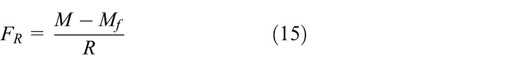
The friction coefficient of rolling friction on hard road is f. We can get
Analysis of obstacle crossing under the double track mode
When encountering stairs, the robot opens double four-link mechanism to pressure at the top of the stairs, as shown in Figure 14(a) and (b), then with the continuous climbing of the robot, elevation gradually becomes larger and the centroid will move slowly, as pictured in Figure 14(c) and (d). If the robot moves to the right side of the left edge of the step, the robot will take the left edge of the step as the center and turn over the top of the stairs.

Obstacle-climbing procedure in double track mode: (a) wheels contacting step edge, (b) gradual expansion process of double four-link mechanism, (c) fully expanded state of double four-link mechanism, and (d) climbing step.
Let the basic structural parameters of the robot be as follows: the radius of the driving wheel is R; the radius of the swing wheel is r; the angle between the bottom track and the ground is
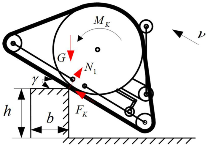
From Figure 14(c), the robot’s track expanded touches the step when the robot is climbing at the step, such that the loading situation during this process is shown by Figure 15. Using the classical mechanics analysis, we can get equations (16)–(18) from the robot’s forces equilibrium equations and its torque equilibrium equation


Loading situation when the robot climbs up the step.
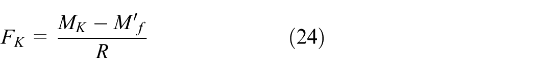
In the way, we can get the traction

During the process, from Figure 14(d) where the tracked mobile robot leaves the stairs and returns to the ground, it twirls around the sharp corner of the top step under the action of gravity until its bottom tracks touch the ground. The supportive force from the sharp corner of the top step to the robot is
Loading situation when the robot leaves the stair.
Based on the classical mechanics analysis, we can get equations (20)–(22) from the robot’s forces’ equilibrium equations and its torque equilibrium equation


The variable

From equations (20)–(23), we can get the traction
According to the phased dynamical model of the robot during the climbing stair process, we can reveal the change law of the required traction and driving torque during the climbing stair process.
Experimental and discussion
Basic performances of the robot
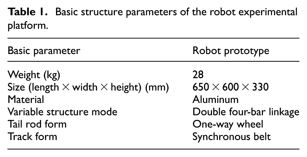
The mobile robot experimental system of the wheel/track variable structure includes the robot platform and the user control terminal (including the PC monitoring interface and remote control), as shown in Figure 17. The operator can control the wheel/track switching, the tail rod rotation, and the forward and backward position of the tracked robot by remote control. All attitude data in the process of operation are transmitted to the computer PC interface through the wireless transmission module, which includes the wheel/track robot’s attitude data. Its basic parameters such as weight, shape, and size, and the structure of each part of the robot platform are shown in Table 1.

Experimental system of the robot.
Basic structure parameters of the robot experimental platform.
The four-link expansion experiment
The experiment is designed to verify that the theoretical design scheme of the double four-link-type deformation mechanism is correct. The track of contraction/expansion process is shown in Figure 18.

Track of contraction/expansion process.
Figure 19 shows the current curves which are produced in the process of expansion and contraction of the variable structure mechanism at rated voltage. First, the expanding time takes about 55 s: Usually, in the middle section, the torque needed is smaller, the required current in the first 20 s and 10 s after is relatively large, and when the value of the current curve rises to about 0.65 A, the torque reaches its peak at the end of the expanding curve. Second, the contraction process takes about 45 s or so, during which progress the whole curve goes steadily. Finally, the load expansion refers to the progress that the swing arm wheel props up the robot’s retractable track. In the first 10 s, the current curve and the expansion process keep a similar growth, and this is because that the swing arm wheel has not begun yet to contact with the track. When the swing arm wheel is contacting the track, the track tension is tighter, the current becomes larger, and the continuous current in the whole process maintains below the rated current 1.2 A of the motor. However, starting from the 60 s, the motor current increases sharply due to the increase in the track tension. Therefore, in actual practice, it is rather important to set a reasonable track open degree.
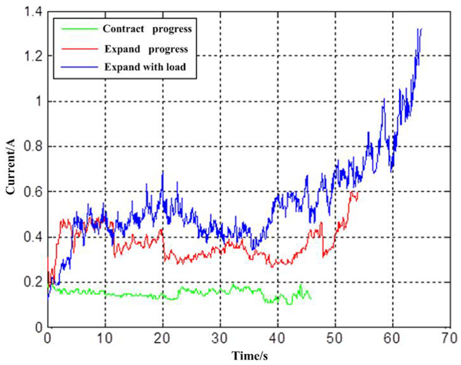
Current chart of expanding and contracting mechanism.
Step topography
The experiments are designed to verify the feasibility of planning the preamble to the robot.
If the robot meets with the condition when the step obstacle is smaller than the wheel diameter, add voltage to make the driving wheel of the robot leave the ground, which is illustrated in Figure 20(a) and (b). However, due to the short robot box body, it cannot play an effective supporting role. As a result, when the voltage increases, the robot does not rise but slip, and at this time we can swing the one-way wheel tail rod which as shown in Figure 20(c) to flat the robot box body, and then the robot will climb over the step. When the robot is climbing down, the tail rod can also play a supporting role to prevent a greater impact; and then the tail rod folds up, the robot successfully completes to cross the step obstacle. This progress is shown in Figure 20(d)–(f).

Wheeled robot obstacle: (a) wheels contacting step edge, (b) climbing up the step, (c) tail rod supporting, (d) climbing down the step, (e) tail rod withdrawing, and (f) completing the obstacle-crossing.
If the tail rod can be swing dynamically, basically the same angle can be maintained to keep the steady body attitude of the robot, while the operation is quite complex. Here, a fix tail rod method is chosen. The fixed tail rod is also helpful to the steady improvement of the robot’s centroid. When the robot meets the step obstacle, it will switch from the wheel mode to the track mode, demonstrated in Figure 21(a) and (b). With the robot climbing up the steps, the inclination angle of the robot becomes gradually bigger and there is no sign of leaning forward, then swing the tail rod to support the rear of the robot to change robot attitude as shown in Figure 21(d). Under the support of the tail rod, the robot subsequently climbs over the following steps, and eventually completes the steps obstacle-surmounting climbing.

Robot climbing stairs experiment: (a) wheels contacting step edge, (b) expansion of double four-link mechanism, (c) tail rod supporting, (d) climbing up the step, (e) tail rod withdrawing, and (f) completing the obstacle-crossing.
The current from each traction motor and velocity of climbing a 30° incline staircase have been recorded by user interface software and plotted in Figure 22.

Experiment results of climbing 30° stairs: (a) current of left drive motor, (b) current of right drive motor, (c) velocity of left side track, and (d) velocity of right side track.
Conclusion
Wheel/track coupling type is a new type of mobile combination compared with the traditional wheel/track multiple robots which only contain one set of walking mechanisms. The structure of a wheel/track coupling-type robot is simple and compact, and it can easily switch between wheel mode and track mode. What is more important, it has a tail rod that can improve the stability of the movement through coordinating the gravity center. This combination is especially suitable for urbanization terrain in which area there are both flat grounds and occasional obstacle steps. Based on the geometry analysis, the theoretical scheme of the double four-bar linkage-type deformation mechanism is designed. The dynamical model of stairs-climbing is established either in wheel mode or in track mode using the classical mechanics analysis on the robot during the stairs-climbing process. The experimental results verify the correctness of the analysis methods of system models of the robot.
Footnotes
Academic Editor: António Mendes Lopes
Declaration of conflicting interests
The author(s) declared no potential conflicts of interest with respect to the research, authorship, and/or publication of this article.
Funding
The author(s) disclosed receipt of the following financial support for the research, authorship, and/or publication of this article: This research was supported by State Key Laboratory of Robotics and Systems (Grant No. 2015-009) and National Nature Science Foundation of China (Grant No. 61273344).