
Abstract
The influence of multimodal incident sound fields on the acoustic behaviour of large aftertreatment devices incorporating a monolith is modelled and analysed in detail. The analytical mode matching method is applied to the compatibility conditions of the three-dimensional acoustic fields at the device geometric discontinuities, leading to the computation of the complex wave amplitudes in all the subdomains involved and the corresponding device transmission loss. To have a realistic model, three-dimensional propagation must be considered in the inlet/outlet ducts and chambers, while one-dimensional wave propagation has to be assumed along the small capillaries of the aftertreatment device monolith (such catalytic converters and particulate filters); therefore, the monolith can be replaced by a plane wave four-pole transfer matrix from an acoustical point of view. On the other hand, for large aftertreatment device inlet ducts such as those found in heavy-duty and off-road engines, the usual models with plane incident wave excitation are not accurate since the onset of higher order incident modes in the inlet duct is expected for the frequency range of interest. Therefore, a variation of the acoustic attenuation performance is likely to occur depending on these modes, similar to the results previously found in the case of large dissipative silencers. Results are presented for three different multimodal incident sound field hypotheses: equal modal amplitude, equal modal power and equal modal energy density. A relevant influence on the sound attenuation is found for the test problems considered in the current investigation.
Keywords
Introduction
Large silencers are commonly used to attenuate noise in many ventilation applications, gas turbine systems, as well as large internal combustion engines (trucks, freight trains, power generation, etc.), among others. For their acoustic modelling and design, the well-established computational methods considered for the relatively small automotive exhaust silencers1–9 can be extended. As these models for small devices usually assume that plane waves are present in the inlet/outlet ducts even if higher order acoustic modes are propagating inside the main body of the silencer, some problems may arise when modelling and computing the acoustic attenuation performance of large devices. If numerical methods such as the finite element method (FEM) are applied,5–8 a large increase in the number of degrees of freedom is required to achieve sufficiently accurate predictions at higher frequencies. When analytical approaches2–4,10 are taken into account, the increase in the number of propagating higher order modes for large configurations significantly affects the silencer performance. 11 This influence is associated not only with the modes inside the central chamber, but also with the modes present in the incident sound field within the inlet port.11–16 It is worth noting that, for large inlet ducts, the excitation is not restricted to a plane wave only and this incident propagation hypothesis no longer holds; thus, a model for multimodal excitation is necessary.
The aforementioned considerations can be extended to a number of aftertreatment devices (ATD) commonly used for the control of pollutant emissions that also have a relevant contribution to noise attenuation, such catalytic converters and particulate filters. One of the main features of these ATD is that they incorporate a central monolith reactor, usually made of ceramic or metallic material with a large number of small parallel channels with thin walls running axially through the core. 17 While the ATD acoustic attenuation performance can be assessed accurately for sizes typical of small automotive exhaust systems assuming incident plane wave excitation,18–23 further research is required for large ATD since the ducts and chambers involved are big enough to allow higher order modes to propagate not only inside the main body of the device but also along the inlet/outlet ports. Therefore, it cannot be assumed that the ATD incident sound pressure field consists solely of a plane acoustic wave.
Following this introduction, Section ‘Overview of the acoustic problem’ presents the acoustic problem under consideration. To have a realistic model, three-dimensional (3D) propagation must be considered in the inlet/outlet ducts and chambers for large devices, while 1D wave propagation has to be assumed along the small capillaries of the central monolith reactor of the ATD; therefore, these monoliths can be replaced by plane wave four-pole transfer matrices from an acoustical point of view.20–23 The mode matching method is then applied in subsection ‘Mode matching method’ to the compatibility conditions of the 3D acoustic fields at the ATD geometric discontinuities, leading to the computation of the complex wave amplitudes in all the subdomains involved and the corresponding transmission loss (TL). On the other hand, for large ATD inlet ducts such as those found in heavy-duty and off-road engines, the usual models with incident plane wave excitation are not accurate since the onset of higher order incident modes in the inlet duct is expected for the frequency range of interest. Therefore, a TL variation is likely to occur depending on these modes, similar to the results found in large dissipative silencers. 11 Therefore, some details are given in subsection ‘Multimodal excitation’ for three different multimodal incident sound field hypotheses:1,12 equal modal amplitude (EMA), equal modal power (EMP) and equal modal energy density (EMED). To conclude this section, the last part is devoted to a brief description of the acoustic models associated with sound propagation in the monolith of a catalytic converter as well as a particulate filter (see subsection ‘Acoustic modelling of the ATD monolith’). Results are presented in Section ‘Results and discussion’ for a number of configurations. First, a comparison is provided regarding the results associated with an ATD incorporating a catalytic converter monolith. These are computed by the proposed mode matching method and also through a FE formulation; in addition, experimental measurements are carried out in a laboratory set-up. As it will be shown, both modelling techniques exhibit an excellent agreement, with undistinguishable TL curves, while benchmarking against experimental attenuation is also very good. Then, further results are shown for two large axisymmetric configurations of ATD incorporating, on the one hand, a catalytic converter monolith, and on the other, a particulate filter monolith. TL computations are carried out with increasing number of higher order modes in the incident acoustic field; in addition, the influence of the mean flow Mach number is assessed in the case of the particulate filter for illustration purposes. As it will be shown, a relevant influence of the multimodal incident sound field on the sound attenuation is found for the test problems considered in the current investigation. To conclude, some final remarks are given in Section ‘Conclusions’.
Overview of the acoustic problem
Figure 1 shows a circular concentric ATD including a monolith. As shown in recent studies,20–23 the sound attenuation of an exhaust device incorporating a monolith can be properly predicted if the monolith is replaced by a plane wave four-pole matrix providing a relationship between the acoustic fields at both sides of the capillary region. Therefore, the presence of higher order modes in the cylindrical inlet/outlet regions is combined with 1D wave propagation within the capillary ducts of the central monolith.

Scheme of a circular concentric ATD incorporating a monolith. The latter is replaced by a transfer matrix to model its acoustic behaviour.
In all the rigid ducts involved (A, B, D and E), the acoustic pressure and velocity fields can be written in terms of a series expansion. For example, the solution of the wave equation in region A is given by1–3

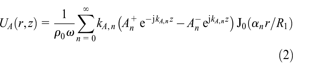
where PA and UA are the acoustic pressure and axial velocity fields,

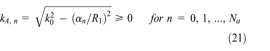
k 0 = ω/c0 being the wavenumber in air, with c0 denoting the speed of sound. The signs associated with the axial wavenumbers are chosen to guarantee exponential attenuation of evanescent modes.2–4
Mode matching method
The complete acoustic field of the system requires the computation of the wave amplitudes
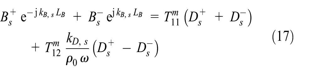
At the inlet expansion, the continuity of acoustic pressure and axial velocity are written as


while the rigid wall boundary condition at the left end plate is given by

The acoustic coupling associated with the monolith at the interfaces SB ≡ SD leads to
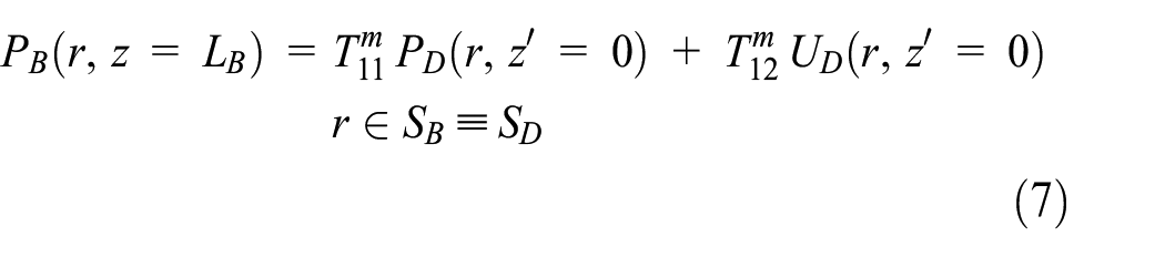
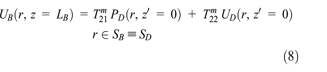
or, in matrix form

where
Finally, similar equations to those considered for the expansion can be written for the contraction (ducts D and E). The continuity of acoustic pressure and axial velocity gives


and the zero axial velocity at the right end rigid plate gives

To compute the wave amplitudes
Starting with the expansion, equation (4) expressing continuity of pressure is multiplied by the transversal modal function
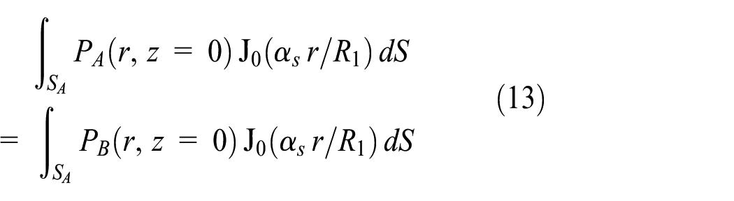
The orthogonality properties of the eigenfunctions1–4,23 lead, for s = 0, 1, 2, …, Na, to

The compatibility of the axial velocity at the expansion is given by equations (5) and (6); these are multiplied by the transversal modal function

Similar to the previous case, for s = 0, 1, 2, …, Nm, the orthogonality properties of the transversal modal functions lead to

The corresponding integrals in equations (14) and (16) can be computed analytically through the expressions detailed in the works,3,4,23 leading to a considerable reduction of the computational effort and speeding up transmission loss calculations.
After considering the expansion, the application of the mode matching method focuses on the monolith. Thus, equations (7) and (8) are multiplied by the transversal modal function

As indicated in Denia et al., 23 it is worth noting here that very simple algebraic expressions have been obtained, where neither integrations nor modal summations appear, relating directly wave amplitudes with equal modal number. These equations do not depend on the transversal cross section, provided that its geometry is axially uniform.
Finally, the equations and integrals associated with the outlet contraction between chamber D and duct E are obtained. Similar to the approach presented for the expansion, equations (10)–(12) associated with the contraction provide a final set of equations as follows. The pressure condition (10) is multiplied by the eigenfunction

Note that the orthogonality properties have already been applied in the right hand side of equation (19). In addition, the velocity conditions (11) and (12) provide, after multiplication by

with s = 0, 1, 2, …, Nm, and where, again, orthogonality has been considered. Also, the integrals in equations (19) and (20) can be computed analytically to reduce the computational expenditure. The reader is referred to the works3,4,23 for further details.
Multimodal excitation
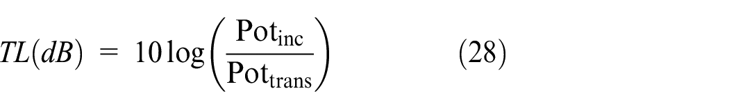
Transmission loss can be evaluated to determine the acoustic attenuation of the aftertreatment device.
2
First, the modal amplitudes
Note that Na can vary during an ATD acoustic computation, increasing as the excitation frequency exceeds the cut-on frequencies of the successive transverse higher order modes.
2
Step 2 requires the computation of the excitation wave amplitudes

Alternative mode mixtures include equal modal amplitude (EMA), equal modal power (EMP) and equal modal energy density (EMED), the corresponding expression being as follows 1 :


where δn depends on the integration of the transversal modal functions over the cross section.
1
Once the excitation wave amplitudes


where Re denotes the real part of a complex number and * is used for the complex conjugate. Finally, in step 5 the transmission loss is evaluated as 2
Acoustic modelling of the ATD monolith
Figure 2 shows examples of monoliths and schemes of the associated flow pattern. Catalytic converter capillaries have upstream and downstream ends open, while particulate filter capillaries are characterized by channel ends alternatively plugged to force the flow through the porous walls.17–21
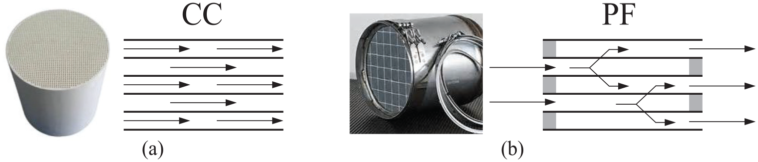
Monolith and flow pattern: (a) catalytic converter (CC) and (b) particulate filter (PF).
Both types of ATD can be modelled by means of a transfer matrix

where ϕcc is the monolith porosity, LC the length of the monolith capillary ducts (see Figure 1) and

and

Rescc being the monolith steady flow resistivity, γ is the ratio of specific heats and sw is the shear wave number calculated as

where α depends on the geometry of the capillary cross section. Also, F in equation (31) is expressed as

where

where J0 and J1 are Bessel functions of the first kind and zeroth and first order. Further information of the acoustic model can be found in Selamet et al. 18
Regarding the particulate filter monolith, only some general aspects are presented in this work for the sake of brevity (the reader is referred to Allam and Åbom 19 for further details). As indicated previously, the acoustic modelling assumes plane wave propagation in the capillaries, which can be computed through transfer matrices involved in equations (7)–(9), (17) and (18), relating the acoustic fields at both sides of the monolithic region. For the case of a particulate filter, if acoustic pressures and volume flows are considered,19,21 this yields

where the corresponding transfer matrix


where mIN and mOUT are the open area ratios at the inlet and outlet, MIN and MOUT are the mean flow Mach numbers in the central chambers B and D, respectively and N is the corresponding number of open channels (approximately half the total number of channels Nt of the particulate filter monolith).
Obtaining the transfer matrix
Regarding the effect on the attenuation of the presence of mean flow and the corresponding gradients, Allam and Åbom
19
indicate that the influence is very small. From a practical point of view, the gradients can be replaced by the use of the average value, giving an error of the order of 0.3 dB for the monolith attenuation. Also, the main impact of the mean flow is related to the area changes in the inlet and outlet, modelled through matrices
Results and discussion
Validation
Figure 3 shows some pictures of a modular catalytic converter prototype with circular cross section. The main radial dimensions are R1 = R3 = 0.0258 m for the inlet/outlet ducts and R2 = 0.1275 m for the chambers and monolith. Regarding the lengths, the values LB = LD = 0.0475 m and LC = 0.075 m are considered in the computations and experimental measurements (see Figure 1 for details).
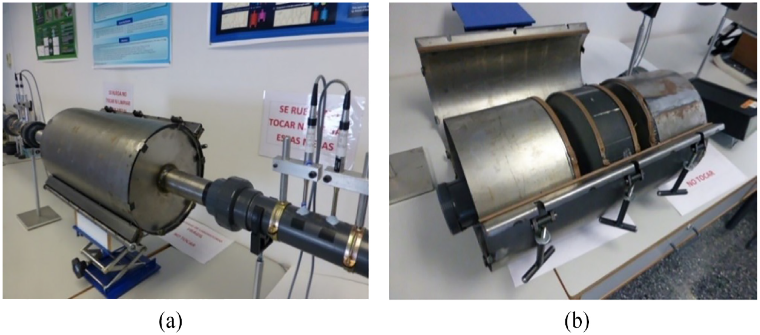
Catalytic converter prototype: (a) external view and (b) open prototype and internal structure.
Cold flow hypotheses with T = 25°C are retained through the computations and laboratory conditions, the properties for the air being c0 = 346.1 m/s and ρ0 = 1.184 kg/m3. Regarding the monolith acoustic model, the following values are considered: resistivity Rescc = 1500 Pa s/m2, porosity ϕcc = 0.88, geometrical factor α = 1.14 (triangular metallic capillaries), dynamic viscosity μ = 1.837 × 10⁻⁵ Pa s, thermal conductivity κ = 0.0255 W/(m K) and specific heat Cp = 1006.4J/(kg K). The detailed model for the four-pole matrix computation can be found in the bibliography.18,22
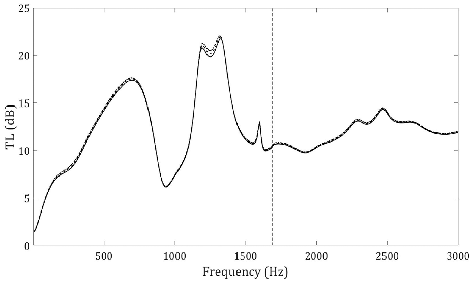
Figure 4 shows a comparison of the results computed by the proposed mode matching method and also through a FE formulation,18,22 as well as experimental measurements carried out in the facilities of the research centre with a set-up based on the transfer function method. 2 As it can be observed, both modelling techniques exhibit an excellent agreement, with undistinguishable TL curves in all the frequency range, while benchmarking against experimental attenuation is also very good, although the usual discrepancies appear due, among other things, to inaccuracies of the experimental measurements for long wavelengths at low frequencies (ineffective anechoic termination, insufficient distance between microphones, etc.), geometric deviations of the tested prototype and approximations associated with the acoustic model of the monolith.

TL of an ATD incorporating a catalytic converter monolith:
It is worth noting that, in the previous results, plane waves are required at the microphone locations to guarantee a correct experimental measurement, the first cut-on frequency being 8180.8 Hz in the inlet/outlet ducts. 2 Multimodal propagation conditions exist, however, in the central chambers B and D, with one higher order mode (Nm = 1 with a cut-on frequency of 1688.6 Hz) in the frequency range considered in Figure 4. Experimental measurement of multidimensional incident modal fields at the inlet duct is a challenge beyond the scope of the current work. As indicated in the literature, to investigate the effect of mode mixture in the incident wave, it is convenient to start by using theoretical models, as these allow one to remove experimental uncertainty in order to focus on the physical processes involved. 14 Therefore, the conclusions obtained to date await more accurate representations of the sound source, as well as supporting experimental evidence, 15 the latter not yet widely available in the literature, at least to the best of the authors’ knowledge.
Acoustic characteristics of the monolith: catalytic converter and particulate filter
Regarding the catalytic converter, two axisymmetric configurations are considered for computation purposes. In the first case, geometry 1 has inlet and outlet ducts defined by the radii R1 = R3 = 0.125 m, while the chambers and monolith are characterized by the radius R2 = 0.25 m and the lengths LB = LD = 0.1475 m and LC = 0.175 m (see Figure 1 for details). In the second case, geometry 2 is defined by the dimensions R1 = R3 = 0.25 m, R2 = 0.5 m, LB = LD = 0.475 m and LC = 0.75 m. It is worth noting that in this latter case radii have been doubled and thus more higher order modes will propagate. Similar to subsection ‘Validation’, cold flow hypotheses with T = 25°C are retained through the computations, the properties for the air being c0 = 346.1 m/s and ρ0 = 1.184 kg/m3. Regarding the monolith acoustic model, the following values are assumed: resistivity Rescc = 1500 Pa s/m2, porosity ϕcc = 0.88, geometrical factor α = 1.14, dynamic viscosity μ = 1.837 × 10⁻⁵ Pa s, thermal conductivity κ = 0.0255W/(m K) and specific heat Cp = 1006.4 J/(kg K). The detailed model for the four-pole matrix computation can be found in the bibliography.18,22
As far as the particulate filter is concerned, the dimensions of geometries 1 and 2 are kept. For the model presented in Allam and Åbom, 19 the following values and parameters are taken into account: plug length lplug = 0.005 m, total number of channels (per square metre) Nt = 3.1 × 10⁵, channel width dh = 1.44 × 10⁻³ m, wall thickness ht = 3.55 × 10⁻⁴ m, wall permeability σw =2.5 × 10⁻¹³ m2, thickness of soot loading hsoot =ht/10 and soot permeability σsoot = 1.5 × 10⁻¹⁴ m2. Also, the mean flow Mach number values MIN = 0, MIN = 0.01 and MIN = 0.02 are considered in region B for illustration purposes (the corresponding values in the inlet duct A are M = 0, M = 0.04 and M = 0.08, respectively) 19 . Finally, the values for temperature, dynamic viscosity, thermal conductivity and specific heat are the same as for the previous case of the catalyst.
Geometry 1: Na = 1
For the conditions associated with this case, the incident modal field has a maximum of one higher order mode (Na = 1) in the inlet duct, its cut-on frequency being 1688.6 Hz, 2 while propagation of up to four higher order modes (Nm = 4) is expected in the central chambers B and D. As it can be seen in Figure 5, the mode mixture rules modify the attenuation of the catalytic converter above this cut-on frequency value; for this particular problem, when incident energy propagates in higher order modes this seems to have a positive impact on the acoustic performance. As observed by Kirby and Lawrie 11 for large dissipative silencers, the three different multimode excitations considered for the incident acoustic field yield comparable results in general, although EMA predictions are lower than both EMED and EMP predictions. For this configuration, the maximum attenuation difference found between the multimodal excitation models and the PW prediction is 3.2 dB (about 30% of discrepancy) at approximately 1690 Hz. The presence of acoustic energy dissipation within the capillary ducts of the monolith leads to a relatively high attenuation, without the undesirable pass bands with low sound attenuation found in purely reactive configurations. In addition, the acoustic behaviour of the device may exhibit resonant characteristics and therefore the ATD transmission loss can benefit from some high attenuation peaks at particular frequencies.

TL of an ATD incorporating a catalytic converter monolith for different modal excitations:
Figure 6 shows the impact of the mode mixture rules on the attenuation of a particulate filter with the same dimensions as the previous catalytic converter (geometry 1) and the properties defined in subsection ‘Acoustic characteristics of the monolith: catalytic converter and particulate filter’. Once again, the differences of acoustic behaviour above the cut-on frequency and the importance of a correct modelling of the propagation conditions are highlighted. It is worth noting that a change in the trend is found for this device, since now EMA predictions are higher than EMED and EMP results over a wide frequency range.

TL of an ATD incorporating a particulate filter for different modal excitations:
Figure 7 shows the TL curves for the previous configuration of particulate filter, considering EMED mixture and three different values of mean flow Mach number in region B given by MIN = 0, MIN = 0.01 and MIN = 0.02, 19 the corresponding values in the inlet duct A being M = 0, M = 0.04 and M = 0.08, respectively. As can be observed, the presence of mean flow leads to a slight TL increase due to the acoustic energy dissipation associated with the monolith expansion/contraction as well as its porous walls (note that the flow is forced to pass through the permeable walls of the particulate filter). This trend is consistent with the results shown in Allam and Åbom. 19
Influence of Mach number on TL of an ATD incorporating a particulate filter for EMED mixture:
Geometry 2 (doubled radii): Na = 4
In this case, the incident acoustic field has a maximum of four higher order modes (Na = 4), the cut-on frequencies being 844.3 Hz, 1545.8 Hz, 2241.6 Hz and 2935.7 Hz respectively. 2 Now, propagation of up to eight higher order modes (Nm = 8) takes place in the central chambers B and D. As shown in Figure 8 for a catalytic converter, the main trends observed in Figure 5 are also found here, the same comments being applicable in general. Anyway, it is worth noting that the larger dimensions of the monolith increase the acoustic energy dissipation, thus leading to higher attenuation levels compared with Figure 5. Now, the relative discrepancies among the TL given by the different models seem to have decreased slightly in the high frequency range. In particular, the maximum attenuation difference found between the multimodal excitation models and the PW prediction is 6.7 dB (about 20% of discrepancy) at approximately 1830 Hz.

TL of an ATD incorporating a catalytic converter monolith for different modal excitations and doubled radii:
Finally, Figure 9 shows the attenuation curves for a particulate filter. Again, it can be observed the evident influence of the mode mixture rules, but now there is some alternation in the frequency intervals where EMED and EMP have a higher TL than EMA, and vice versa. As expected, the larger dimensions of this filter compared with the one associated with Figure 6 lead to higher TL values. Also, as for the case of the catalytic converter (Figure 8), the relative differences among the acoustic attenuation at high frequencies given by the different approaches seem to have decreased slightly compared with geometry 1.

TL of an ATD incorporating a particulate filter for different modal excitations and doubled radii:
Conclusions
An accurate and efficient computational method has been presented for the acoustic modelling of large ATD with a monolith, considering both a catalytic converter as well as a particulate filter. The model is based on the analytical mode matching method and assumes 3D wave propagation in the inlet/outlet regions (ducts and chambers) and 1D wave propagation along the small capillaries of the central monolith reactor. In large ATD, plane wave (PW) propagation in the inlet/outlet ducts no longer holds for the frequency range of interest, and energy incident on the device propagating in higher order modes may have a strong impact on the acoustic attenuation performance. The specification of the incident modal field requires a knowledge of the source characteristics, but this is currently an open field of research and there is a lack of accurate representations as well as experimental validation. In addition to the PW model, several mode mixtures have been implemented: equal modal amplitude (EMA), equal modal power (EMP) and equal modal energy density (EMED). As expected, a strong influence of the mode mixture technique on the attenuation has been found. The three different multimode conditions adopted for the incident sound field can yield predictions that are consistent with the literature for some particular configurations of catalytic converter, in the sense that at higher frequencies the acoustic performance of the exhaust device generally improves when energy from the source is carried by higher order modes (especially if dissipative effects are present in the analysis, such as those taking place within the capillary ducts of the monolith). However, the opposite trend can also be found for other configurations of particulate filter and thus, a plausible conclusion is that an accurate transmission loss estimation in large ATD requires the consideration of multimodal excitation, but the results are strongly dependent on the particular configuration under analysis and the mode mixture rule chosen. Although literature seems to suggest that EMED is probably the most suitable model, this depends on the noise source characteristics and further work is required.
Footnotes
Handling Editor: Chenhui Liang
Declaration of conflicting interests
The author(s) declared no potential conflicts of interest with respect to the research, authorship, and/or publication of this article.
Funding
The author(s) disclosed receipt of the following financial support for the research, authorship, and/or publication of this article: Project supported by Grant PID2020-112886RA-I00 funded by MCIN/AEI/10.13039/501100011033 and Project PROMETEO/2021/046 from Generalitat Valenciana.