
Abstract
The method of force compliance was proposed during process of the manipulator cooperating with the movement of the forging press, which could avoid the destructive effect generated by the deformation resistance of the workpiece for the key parts. Taking the 20T forging manipulator as the target, the inverse kinematics model and the dynamic model of the major-motion mechanism were established. Through taking the pressure as the controlled variable, the dynamic model of the hydraulic lifting system was built. Based on the buffering principle, the mathematics model of the horizontal buffering system was deduced. Taking the deformation model of workpiece as the input, the variations of the displacements and forces for hydraulic cylinders were obtained by the simulation. Finally, the effectiveness of active pressure compliance method of the lifting control system using the classical proportional–integral–derivative control strategy and that of the passive compliance method for the buffering system were verified.
Keywords
Introduction
Forging manipulator is an important equipment, which is mainly used for clamping forgings and supporting press to forge. 1 As the key equipment, the forging manipulator need to cooperate with the movement of the forging press, so the compliance ability of the overloaded operation equipment reacting against uncertain load is the key to ensure that the equipment can operate stably and reliably. Since the manipulator bears the deformation resistance generated by the workpiece, the compliance process of manipulator can improve the load-bearing capacity.2–4 Meanwhile, the compliance process ensures the manipulator adapt to different working conditions effectively. The compliance behavior of forging manipulator is mainly achieved through two ways: active compliance and passive compliance.
Active compliance method is normally used in the vertical direction of the forging press: Zhou et al. 5 used the spool displacement compensation strategy of the proportional directional valve to study the cushioning property for the manipulator lifting system. Yang 6 analyzed the cushioning property of the lifting system by setting up the machine-liquid model for the manipulator. Lilly and Melliger 7 carried out a simulation analysis for the manipulator’s dynamic behavior and designed a neural network compliance control strategy. Nye and Elbaoanl 8 used online measurement technology and the empirical formula to optimize the compliance process of the manipulator. The above literatures used different control strategies to conduct the research of the displacement compliance for the manipulator.
The displacement control strategies only apply to the workpiece whose shape is relatively regular and the deformation degree can be predicted in a reasonable range. If the shape of the workpiece is complex or the deformation is irregular, it is hard to predict the movement curve of the manipulator. And it is easy to produce excessive force because of the motion conflicts between the manipulator and the press. Due to the workpiece’s irregular deformation during the forging process, the control strategies of the displacement tracking the press will let the lifting system bear additional force. 9 What’s more, the workpiece produces plastic deformation during the forging process, the gravity center of the workpiece moves down, so the lifting system of the manipulator directly endures the pressure of the forging press. If the force compliance is not enough, the lifting system and the institutions will bear the large load which could destruct the key parts of the manipulator, so the force compliance is more important. The pressure can be used as the controlled object to achieve the active compliance of the lifting system.
In the lateral direction of the forging press, passive compliance is general used: Zhao et al. 10 analyzed the passive compliance process of the manipulator by establishing the dynamic model of the buffering overflow system. Wang et al. 11 carried out a multi-discipline simulation analysis in the passive compliance process of the buffering overflow system. However, the use of buffering overflow system is not conducive to the recycle of energy. If the method of the accumulator cooperating with the buffering cylinder is used to carry out the compliance, the energy can be used effectively because of the energy absorption characteristics for the accumulator.
In this article, taking the pressure as the controlled variable, the dynamic model of the lifting hydraulic control system was established to research the active pressure compliance. For the horizontal buffering system, the passive compliance method of the accumulator cooperating with buffering cylinder was proposed, and the model of the horizontal buffering hydraulic system was deduced. Finally, a united simulation model of the workpiece in the forging process was built to analyze the effectiveness of active pressure compliance and passive compliance, which could provide technical support for the forging integrated automation.
Deformation model of the workpiece
During the forging process, when the upper die of the forging press contacts with the workpiece, the force of the forging press let the workpiece occur the plastic deformation in a short time, and large impact load are formed on the clamp of the manipulator. Taking the rectangular workpiece as an example, the forging process can be planned: the clamp grasping the workpiece—the lower die fixing—the upper die working down to forge the workpiece—the workpiece occurring plastic deformation. The forging process is shown in Figure 1. Before forging, the length, width, and height of the workpiece are, respectively, expressed as l0, w0, and h0. After forging, the length, width, and height of the workpiece are, respectively, expressed as l1, w1, and h1. The contact width between the upper die and the workpiece is b. When squeezed by the upper die and lower die, the workpiece is deformed and produced forces along the x, y, and z direction. But only the forces of two directions (x and y) affect the clamp, where x is expressed horizontal direction (axis direction of the workpiece) and y is expressed the vertical direction (moving direction of the upper die). The deformation displacement can be expressed by the O point coordinate. According to the literatures,12,13 the expressions of the O point are shown as


where

The forging process of workpiece.
Model of major-motion mechanism
Major-motion mechanism for forging manipulator
Taking the 20T forging manipulator as the object, the diagram of the major-motion mechanism of the manipulator is shown in Figure 2. The mechanism has eight components, three of which are driving cylinders. And they are the lifting cylinder O1F, the pitching cylinder BC, and the horizontal buffering cylinder O3G. Other components include the forearm O4DFE, the rear arm O2AB, the connecting rod AD, the boom EH, and the claw beam CH. The parallel 4-linkage mechanism O2O4DA is composed of the forearm and the rear arm. The lifting movement of the claw beam is completed by the lifting cylinder O1F. The pitching cylinder BC completes the pitching movement and the horizontal buffering cylinder O3G completes horizontal movement. In the forging process, the pitching cylinder is locked. The changes in the clamp position can cause corresponding changes in each component. The d1 represents the piston displacements of lifting cylinder, and d2 represents the piston displacements of horizontal cylinder (d10 represents the initial length of lifting cylinder before forging and d20 represents the initial length of horizontal cylinder before forging).
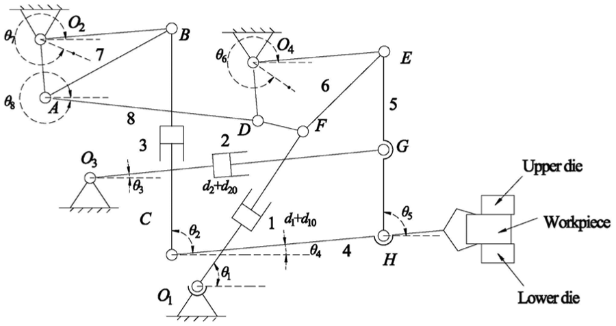
Diagram of major-motion mechanism for forging manipulator.
Inverse kinematics model of major-motion mechanism
During the forging process, the action of electro hydraulic system is not a simple matching with the deformation of the workpiece. Therefore, it is necessary to establish the inverse kinematics model of the major-motion mechanism. Taking the deformation expressions of workpiece as an input, the inverse kinematics model of the major-motion mechanism is built through the plural vector method.
During the forging process, the displacement of the claw beam and the deformation displacement of the workpiece are the same, so the movement curve of the joint H is consistent with the deformation curve of the workpiece. From formulas (1) and (2), the coordinate of the joint H can be expressed as

where
When the expression of the joint H is known, the kinematic expressions of the components can be expressed as


where ui is the position coordinate expression of the i component, i = 1, 2, …, 8;
By taking the first derivative and second derivative of formula (4), respectively, the velocity and acceleration of the i component are expressed as


where
By taking the first derivative of formula (5), the speed expression of the j cylinder is expressed as

where
By solving the simultaneous equations (4) and (8), the velocity expression of the kinematic relationship is written as

where
Through letting

where
Dynamic model of major-motion mechanism
Based on the principle of virtual work, the dynamics model of major-motion mechanism during the forging process is derived.
According to the principle of virtual work, the elementary work

where
By solving the simultaneous equations (10) and (11), the elementary work

where Ji is the component of the Jacobian matrix
The elementary work

where
The elementary work

where
According to the principle of virtual displacement, the expression can be written as

Through the Jacobian matrix of the kinematics, the expression can be written as

By solving the simultaneous equations (15) and (16), the force of the hydraulic cylinder can be expressed as

Dynamic model of lifting hydraulic system
Taking the pressure as the controlled variable, the dynamic model of the lifting hydraulic control system is established. The complete hydraulic system has been introduced. 14 For simplified calculation, the lifting system can be simplified as the system which is made of the valve and the asymmetric cylinder. The system diagram is shown in Figure 3. When the workpiece works in the forging condition, the deviation signal is taken as the input signal gotten through the command pressure signal subtracting the feedback pressure signal which is detected by the pressure sensor. Through the proportional–integral–derivative (PID) controller, the deviation signal drives the proportional valve to work in the right position. With the gravity action of the clamp and the workpiece, the oil of the rodless cavity in lifting cylinder returns to the tank through proportional valve. So, the active compliance motion is realized.

The principle diagram of lifting control system.
The mathematical model of the lifting system is established through Figure 3.
After the linearization, the flow equation of proportional directional valve is shown as

After the linearization, the flow continuity equation of lifting cylinder is shown as

The force balance equation of the lifting cylinder (neglecting the nonlinear friction force, viscous force and elastic force) is shown as

where
The transfer function between the spool displacement of the proportional direction valve and the input current is shown as

where
Deviation signal is shown as

where
The output voltage of pressure sensor is shown as

where
The output current of proportional amplifier is shown as

where
From formulas (18) to (24), the block diagram of lifting system is shown in Figure 4.

Block diagram of lifting control system.
Dynamic model of horizontal buffering system and the selection of accumulator
Dynamic model of horizontal buffering system
To simplify the research of the system, the principle diagram of horizontal buffering system is shown in Figure 5. When squeezed, the workpiece produces a deformation force. The deformation force acts on the buffering cylinder through the clamping rod and pushes the piston of the buffering cylinder to the left. Finally, the hydraulic oil is pushed into the accumulator and the bladder of accumulator is squeezed. So, the passive compliance motion is realized.
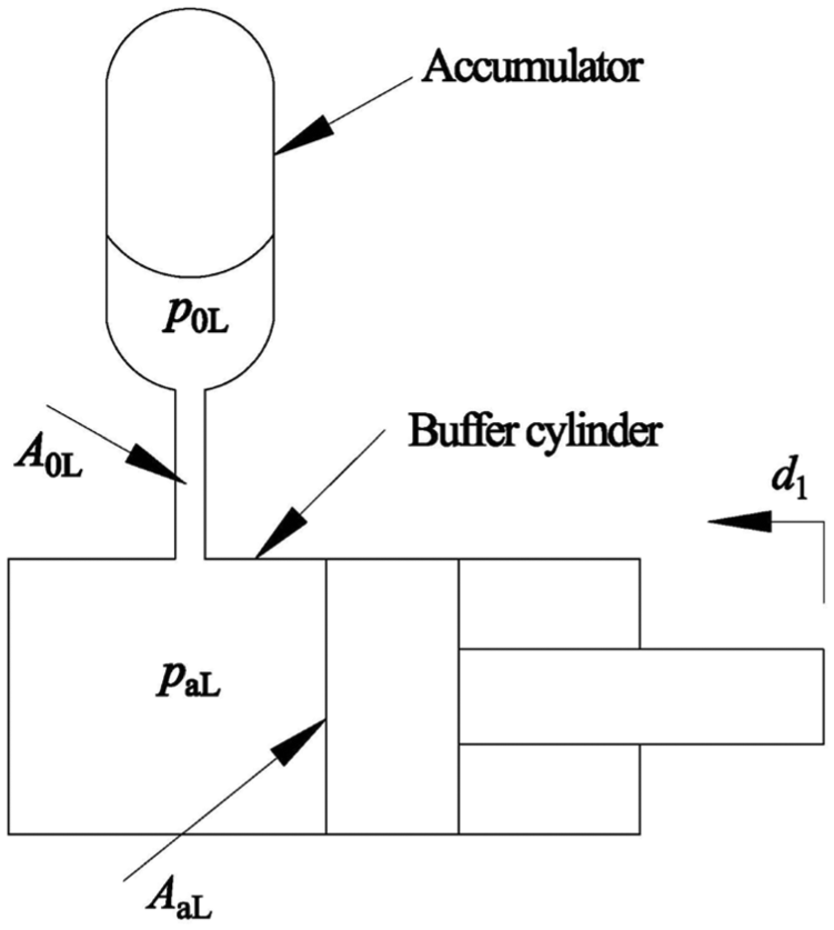
Principle diagram of horizontal buffering system.
Assuming that the hydraulic oil is incompressible fluid, the flow equation of the horizontal buffering cylinder is shown as

where
The orifice flow equation of the accumulator is shown as

where
According to Bernoulli equation (ignoring the gravity and the pressure loss along the pipeline), it can be gotten that

where
The accumulator pressure
The output liquid of the horizontal buffering cylinder is the same as the input liquid of the accumulator, and it can be expressed as
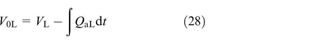
where
The characteristic equation of the bladder accumulator is shown as

where γ is the adiabatic coefficient, γ = 1.4, and C is the constant.
From formulas (29) and (30), the p0L is shown as

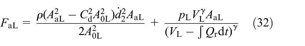
The output force of the horizontal buffering cylinder is shown as

where
From formulas (25)–(31), the
Selection and calculation of the accumulator
Determination of air pressure in the accumulator
In terms of protecting the accumulator bladder and prolonging the service life, the air pressure

Determination of air volume of accumulator
According to Boyle’s law

From formula (34), it can be gotten that

where
Results and discussion
The MATLAB/Simulink software is used to set up workpiece-institutions-hydraulic simulation model. With the aid of this simulation model, taking the deformation of workpiece as an input, variation laws of the displacements and forces of cylinders are analyzed during the forging process. Through the classical PID control method, the effectiveness of active pressure compliance of the lifting control system is analyzed. The effectiveness of passive compliance of the horizontal buffering system is analyzed, which is composed of a buffering cylinder and an accumulator. It is assumed that the workpiece is lifted to the middle position and the clamp is in the horizontal position. Taking the above 20T manipulator as the object, the main parameters are shown in Table 1.
Main parameters of major-motion mechanism for forging manipulator.

The variation laws of the piston displacement and force for cylinders
In order to study the variation laws of the piston displacements and forces of cylinders, different h (total forging depth) and b (upper die contact width) are, respectively, taken to complete the simulation. The curves of the variations laws are shown in Figures 6 and 7.

Piston displacement curve of cylinders: (a) piston displacement curve of lifting cylinder with different h, (b) piston displacement curve of buffering cylinder with different h, (c) piston displacement curve of lifting cylinder with different b, and (d) piston displacement curve of buffering cylinder with different b.

Reaction force curve of cylinders: (a) force curve of lifting cylinder with different h, (b) force curve of buffering cylinder with different h, (c) force curve of lifting cylinder with different b, and (d) force curve of buffering cylinder with different b.
From Figures 6 and 7, it can be seen that the piston displacements of the lifting cylinder and the buffering cylinder decrease with the forging time, the force of lifting cylinder gradually decreases, and the force of buffering cylinder gradually increases. From Figures 6(a) and (b) and 7(a) and (b), it can be seen that under the same condition (b = 200 mm), the larger the total compression heights of the workpiece (h), the greater the changes of the piston displacements and the forces of the cylinders. From Figures 6(c) and (d) and 7(c) and (d), it can be seen that under the same condition (h = 100 mm), changes of the contact width (b) have little influence on the piston displacements and forces of the cylinders. In particular, the influence can be neglected for lifting cylinder. From Figures 6 and 7, it can be seen that the piston displacement of the lifting cylinder is greater than that of buffering cylinder and the force of lifting cylinder is larger than that of the buffering cylinder.
Through the analysis of kinematics and dynamics in the forging process, it can be concluded that the larger the total compression heights (h) of the workpiece, the greater the changes of the forces of the cylinders. So, the variation laws gotten by different h are used to study the active pressure compliance and the passive compliance of the cylinders.
Active pressure compliance of lifting system
Based on the dynamic model, the force of the lifting system is gotten by different h. Through the force of the lifting system dividing the area of rodless cavity, the pressure

Active compliance curve of lifting system.
Following error curve of lifting system.
From Figures 8 and 9, it can be seen that the tracking error increases with the increase of h. When h is 100 mm, the maximum tracking error of the response curve is 0.0028 MPa. When h is 200 mm, the maximum tracking error is 0.0039 MPa. When h is 300 mm, the maximum tracking error is 0.0059 MPa. But the overall error is small. So, it can be concluded that the pressure can track the command signal well and has good active compliance.
Passive compliance of the buffering system
Through the force analysis of the buffering cylinder during forging process, it is known that the maximum force of horizontal buffering cylinder is 109.12 kN and the minimum force is 70.59 kN. Solving the formula (31), it is known that the maximum working pressure of buffering system is 5.46 MPa and the minimum working pressure is 3.53 MPa. Solving the formula (33), it is known that the air pressure of the accumulator is 3 MPa. Solving the formula (35), it is known that the total volume of the accumulator is 0.021 m3. Since the accumulator is the standard component, the total capacity
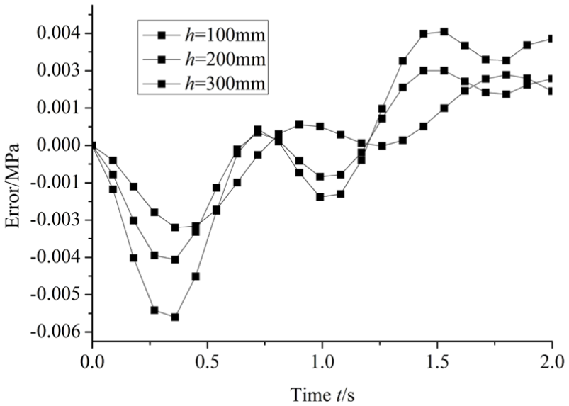
To analyze the effectiveness of passive compliance for horizontal buffering system, the initial pressure of the system is taken as 3.53 MPa before the forging process. Based on inverse kinematics model, the piston displacement of the horizontal buffering cylinder under different h is gotten. Solving the equation (32) by taking the piston displacement as the input, the output force is gotten. The output force is used to compare with the signal force which is gotten through the dynamic model under different h, so the passive compliance curve and the error curve of the horizontal buffering system are gotten. They are, respectively, shown in Figures 10 and 11.

Passive compliance curve of buffering system.

Error curve of buffering system.
From Figures 10 and 11, it can be seen that with the increase of h, the passive compliance error increases gradually, and the error tends to be the largest in later stage of the passive compliance. The reason is that the gas of the bladder is exposed to the single direction compression and exerts the function of hydraulic gas spring in the compliance process. Affected by this, the output force of buffering cylinder is larger than the force which is gotten through the dynamic model in later stage. When h is 100 mm, the error is 1.02 kN. When h is 200 mm, the error is 2.89 kN. When h is 300 mm, the error is 3.69 kN. But the overall error is not large. So, it can be concluded that the buffering system can realize passive compliance, and the selection of buffering system is right.
Conclusion
The following conclusions can be drawn:
First, the method of the force compliance is proposed during the process of the manipulator cooperating with the movement of the forging press, which could provide technical support for the forging integration.
Second, the variation laws of the displacements and forces for the cylinders are analyzed in a dynamic perspective. The piston displacements of the lifting cylinder and buffering cylinder decrease with the forging time, the force of the lifting cylinder decreases gradually, the force of the buffering cylinder increases gradually, and the force of the lifting cylinder is much larger than that of the buffering cylinder.
Third, taking the pressure as the controlled variable, the dynamic model of the lifting hydraulic control system is established. And the classical PID control strategy is used in the system. The validity of active pressure compliance is verified through the dynamic model.
Fourth, the horizontal buffering method of the manipulator is proposed. The system which is composed of the buffering cylinder and the accumulator is beneficial to saving energy and reducing fever.
Footnotes
Academic Editor: Changwon Kim
Declaration of conflicting interests
The author(s) declared no potential conflicts of interest with respect to the research, authorship, and/or publication of this article.
Funding
The author(s) disclosed receipt of the following financial support for the research, authorship, and/or publication of this article: This study was supported by the National Natural Science Foundation of China (51175148) and the Key Scientific Research Program of Henan Provincial University (15A460001).