
Abstract
In this study, two design configurations routinely adopted in actual mass production for deep groove ball bearing rings of multi-stage warm forging process are investigated numerically and experimentally. The deformation mechanism, forging defects, microstructures, and compositions analysis are the main focus of this study. For type A design with a stepped configuration, inner and outer rings are automatically pierced and separated in the multi-step forging machine. On the other hand, for the type B geometry, additional step is required by the customized milling machine. For type A design, the main issue encountered during actual forging process is the inadequate material filling at the upper corner radius and folding defects at the transition area of inner wall of forgings. For type B design, the material flow is unsatisfactorily directed and lower outer radius is insufficiently filled. Therefore, variations of forging parameters include billet weight, punch/knock out pin geometry and the effect of lubricating fluid is systematically investigated. In addition, the finite element method has been performed and compared with the actual forging experiments. In summary, the modification of tooling design, dimension variation of billet weight, and the forging temperature difference as impacted by the lubricating fluid, which are identified as the three major factors of the forging integrity and stability of the mass production process. The results are particularly useful for the advanced tooling design and contribute largely to minimize the tool failure and the integrity of the bearing forged.
Introduction
Rolling elements are almost ubiquitous in many industrial sectors to implement the proper torque transfer, particularly in the transmission of various vehicles. 1 Generally, containers of rolling balls, typically called inner ring (IR) and outer ring (OR), are equipped with a set of rolling elements (typically balls or columns) running in a cage-guided tracks and protected by rubber seals or metal shields.2,3 The above-mentioned key components are mainly manufactured by metal forming technology. In particular, warm forging technique has been widely applied to make the constant velocity joint in the transmission box and many complex parts can be fabricated by the forging technique.4–6
The knock out pin (KOP) and punches in forging operations can be harshly subjected to many types of stresses in the forms of mechanical, thermal, chemical, and tribological loading cycles. 7 Therefore, redesigned the geometry of punch and KOP to minimize the punch ejection load 8 and extended tooling life can be achieved via the optimized mold geometry.9,10 Furthermore, the major characteristics of excessively worn tooling and forging defects are previously identified as the primarily failed mechanisms. 11 One of the crucial consideration employed by the forging industry is the lubricant selection and implementation. Conversion coatings, mineral oils, and solid lubricants11,12 are all potential candidates and for severe warm forging operations, an efficient conversion coating is indispensable to alleviate the high interface pressure and larger surface expansion.13,14
Numerical simulation is capable of routinely modeling stress, strain, and forging load during the hot forging process. 15 Commercially available finite element (FE) software was extensively used to simulate the various stages of metal forming processes. 16 Currently, a variety of forging induced imperfections can also be performed on a commercial software. 17 Die design for connecting rods with minimal flash by FE to save material costs was reported. 18 The thermo-mechanical manufacturing process of a connecting rod is analyzed by finite element method (FEM); several rolling and forging stages were included. 19 The tooling can be pre-designed by means of FE to predict both the mechanical properties and the microstructure evolutions at different forging temperatures.20,21 Furthermore, FE analysis of the ring rolling process is the recent focus to simulate the effect of size of forming rolls, the hydraulic adjustment mechanism, and the key technological parameter design of the hydraulic ram.22,23 FE analysis was also utilized in the multi-directional forging presses to simulate the stiffness and deformation characteristic of preload frame structure under different loading states. 24 Moreover, a FE model has been developed to simulate the residual stresses as generated from quenching T-section components of AA7050 aluminum alloy. In particular, the recent investigation on the multi-stage warm forging (MSWF) process of deep groove ball bearing (DGBB) had been performed numerically and experimentally with the impact of a modified punch geometry as well as relevant microstructure and defect analysis. 25
In this article, the design–simulation–remodified tooling stages on the actual forging process of die/punch geometry are presented in detail. In addition, the deformation mechanism is centered on two configurations that actually employed in the mass production of bearing forging processes. These works have revealed that modification of tooling design, dimension variation of billet weight, and the forging temperature difference as impacted by the lubricating fluid are the three contributing factors for the stability of MSWF technique of DGBB.
Deformation mechanism of finish forging tooling
Introduction of MSWF
The DGBBs are the most commonly utilized machine elements in numerous sectors of industry. Figure 1(a) shows the schematic of DGBB. Structurally speaking, DGBBs are primarily composed of two containers with specific configurations, that is, OR and IR, rolling elements such as steel balls and the protection elements of rubber seals or metal shields, as shown in Figure 1(b). In particular, the precisely guided rolling elements are of crucial importance such that the uniform spacing and relative motion should be carefully maintained. Therefore, the MSWF process is the main production method to produce the OR and IR since the grain flow of forging parts can be ensured. There are two major production methods which adopt MSWF process in fabricating DGBB, as shown in the flowchart (Figure 2). The major difference is the tooling geometry of finish forging (FF), that is, stepped configuration and pancaked counterpart. The reason for classifying these two methods involves a complicated consideration and may be primarily judged by the final product dimension, weight, machine capability, post-processing steps, and production volume. The geometry of FF illustrates the major difference as indicated method 1 (type A) and method 1 (type B), respectively. For type A forging with a stepped configuration, IR/OR are automatically separated on the multi-step forging machine. Spheroidizing and ring rolling are also performed for the IR/OR parts. On the other hand, for the type B forging, separation of IR/OR parts is performed by the customized milling machine. Material yield in the FF process of type A and B achieves 9% and 6.5%, respectively, mainly due to the remaining materials between the upper punch and knock pin. Both methods adopt the steel rods as starting billets to minimize the waste ratio.
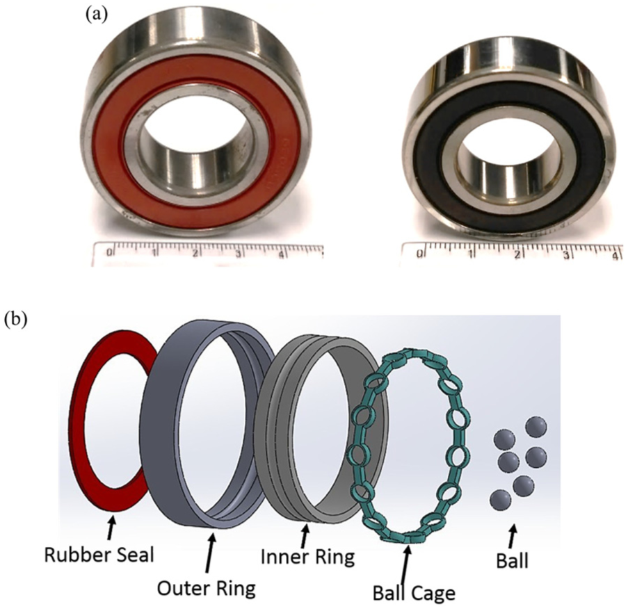
The key components of DGBB used for automobiles and other precision machineries: (a) assembled DGBB and (b) schematic view of the key components for DGBB which includes outer ring (OR), inner ring (IR), rubber seal, ball cage, and ball.
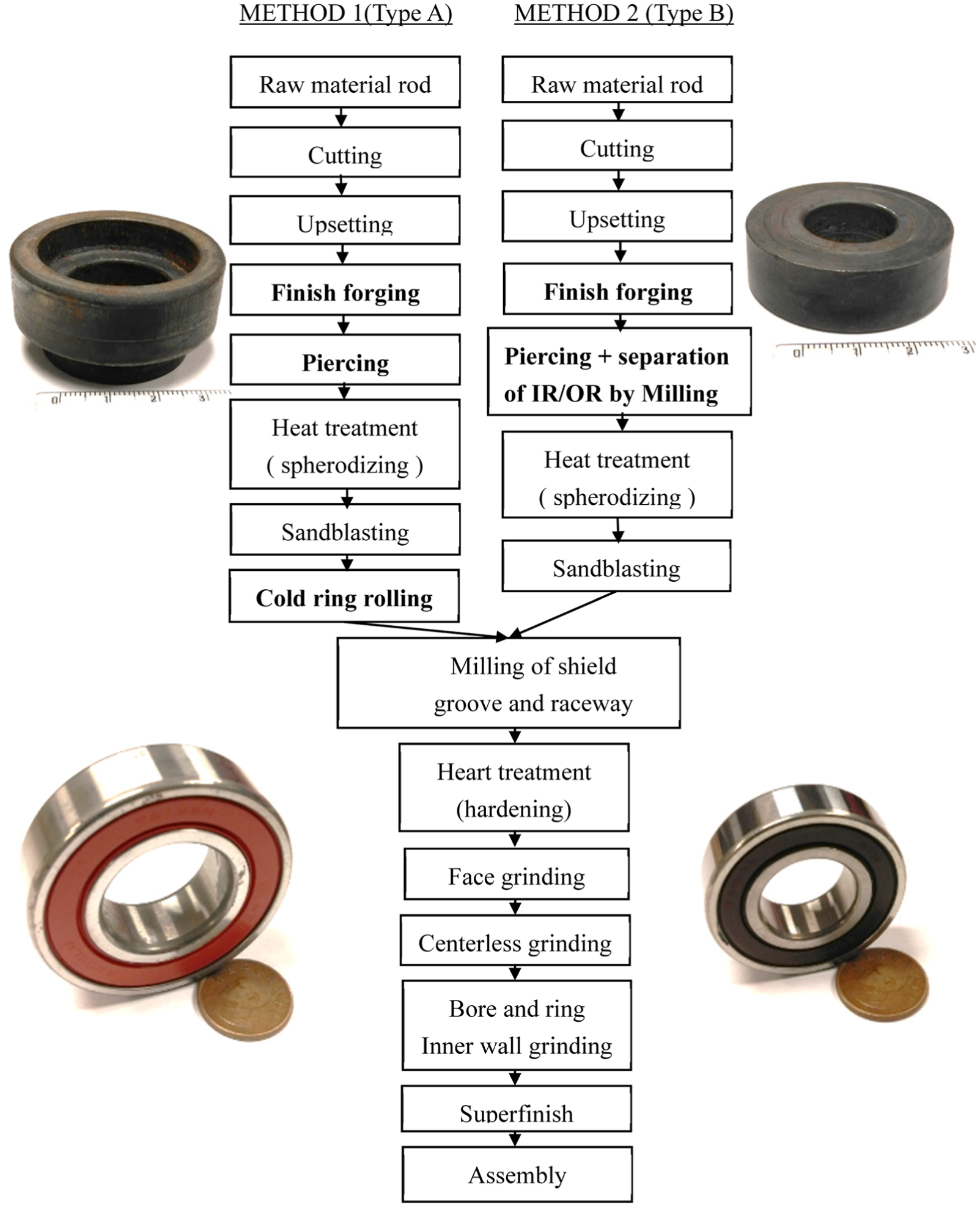
Flowcharts of two different forging ring design and manufacturing scenarios of finish forging (FF) in the production for DGBB.
Sequentially compressive deformation of the starting billet material is the primary driving force in the MSWF process. Figure 3 displays the total manufacturing steps of type A/type B bearing production processes, which include billets shearing (the temperature is set at 1150 °C), one upsetting operation, one fully closed die FF, piercing and separating operations. In the process of type A (stepped, top) in station 2, the upsetting ratio and degree of upsetting can be calculated as
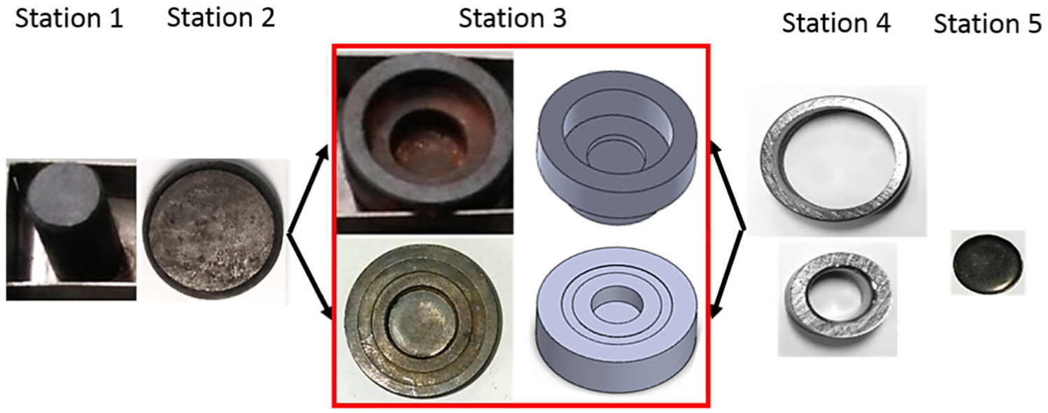
Production stages of finish forging, showing the actual photos and 3D CAD schematics of MSWF. Two different ring designs of finish forging are investigated as type A (stepped, top) and type B (pancaked, bottom) configurations.
Study of MSWF
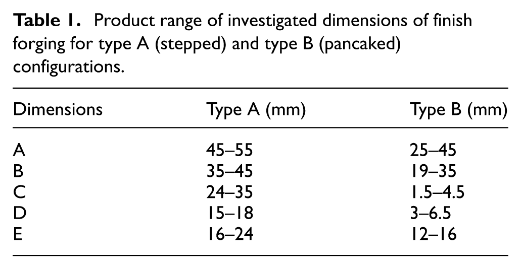
Figure 4 illustrates the optical photos, detailed dimensions, and cross-sectional view of FF by MSWF process for type A (top) and type B (bottom). In the traditional MSWF process for making the OR and IR of the DGBB, all the metal forming steps are sequentially performed on the hot former (Sakamura BP-350). Figure 4(a) and (b) shows the critical dimensions of FF for the type A forging, contains the IR diameter (B, C), height (D), OR diameter(A, B), and height (E), as shown in. Material yields are ∼9% and 6.5% of billet weight, respectively. Optimized upper punch geometry and knock pin relief angles are suggested in this study, based on the deformation mechanism of MSWF. In addition, the product range of investigated dimensions of FF for type A (stepped) and type B (pancaked) configurations is shown in Table 1. For type A configuration, the dimensions of OR and total height are comparatively larger than the type B counterpart; therefore, the material flow and deformation status will be different in the FF process as investigated in the next sessions.
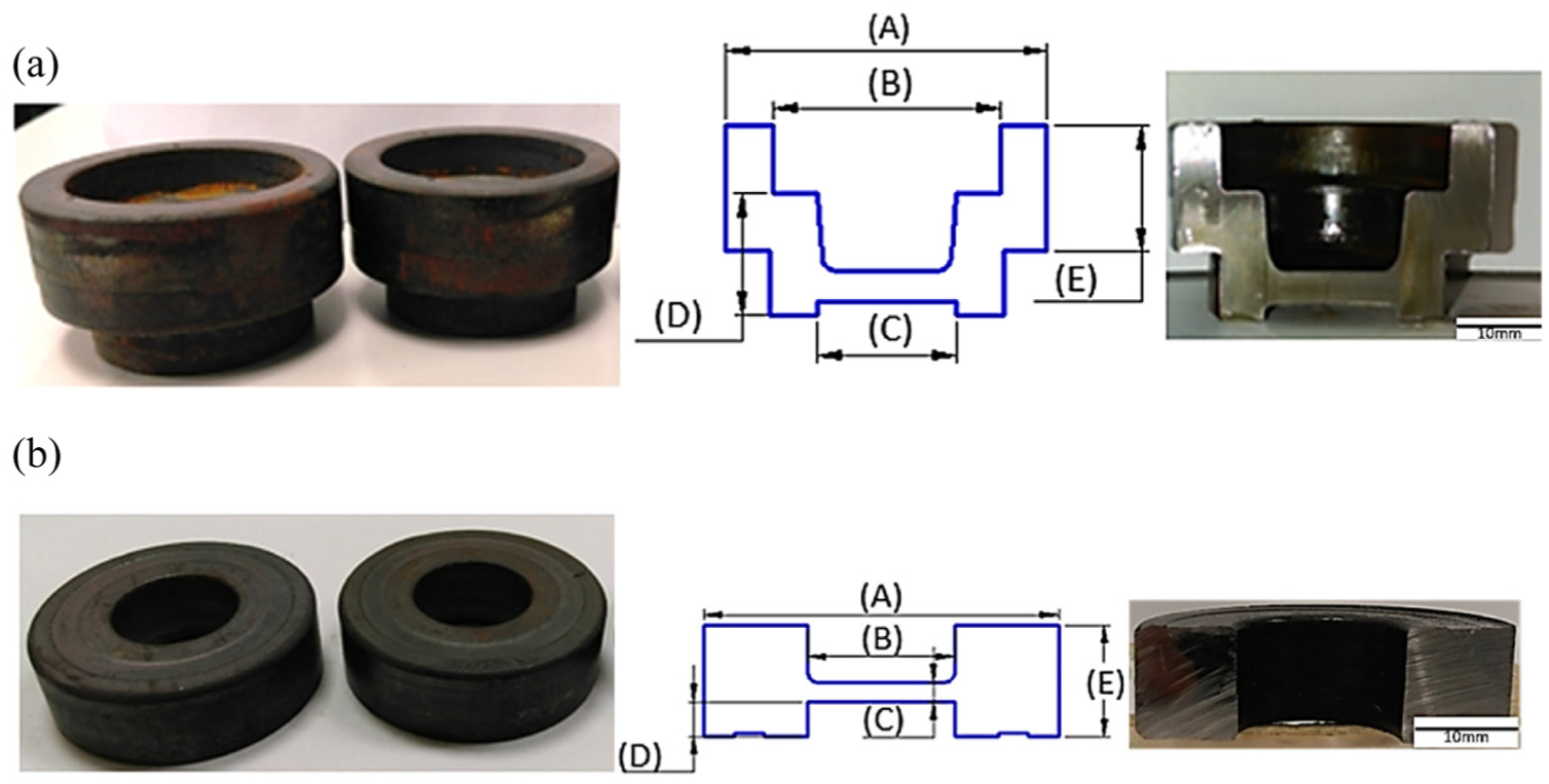
Actual forging results and detail dimensions for (a) type A ( stepped) and (b) type B (pancaked) configurations. The scale bar is 10 mm.
Product range of investigated dimensions of finish forging for type A (stepped) and type B (pancaked) configurations
The billet material is the standard bearing steel SUJ2 (AISI 52100), which is commonly utilized to the moving components of rotating or/and linear motions such as motors, ceiling fans, and locomotive. The detailed tooling of FF in both type A and type B bearing is presented in Figure 5 for the MSWF process. The key components of tooling are presented in Figure 5. The materials used are mainly the heat-resistant tooling steels, in particular, high tough strength tooling steels of SKD61 and SKH9. In comparison, the tooling geometry of type A and type B differs significantly in the configuration of upper punch, one is the stepped design and the other is the pancaked design. In both configurations, the SKH9 is used for the upper punch materials due to the severe requirement of forging load, temperature, and tooling wear issues. Another key characteristics is the design of KOP with a total of 54 holes at 2 mm diameter. In order to minimize the thermally induced wear, KOP is intentionally modified to enhance cooling capability using the massively and circumferentially oriented cooling passages, as shown in the optical photos of KOP in Figure 5(a) and (b)
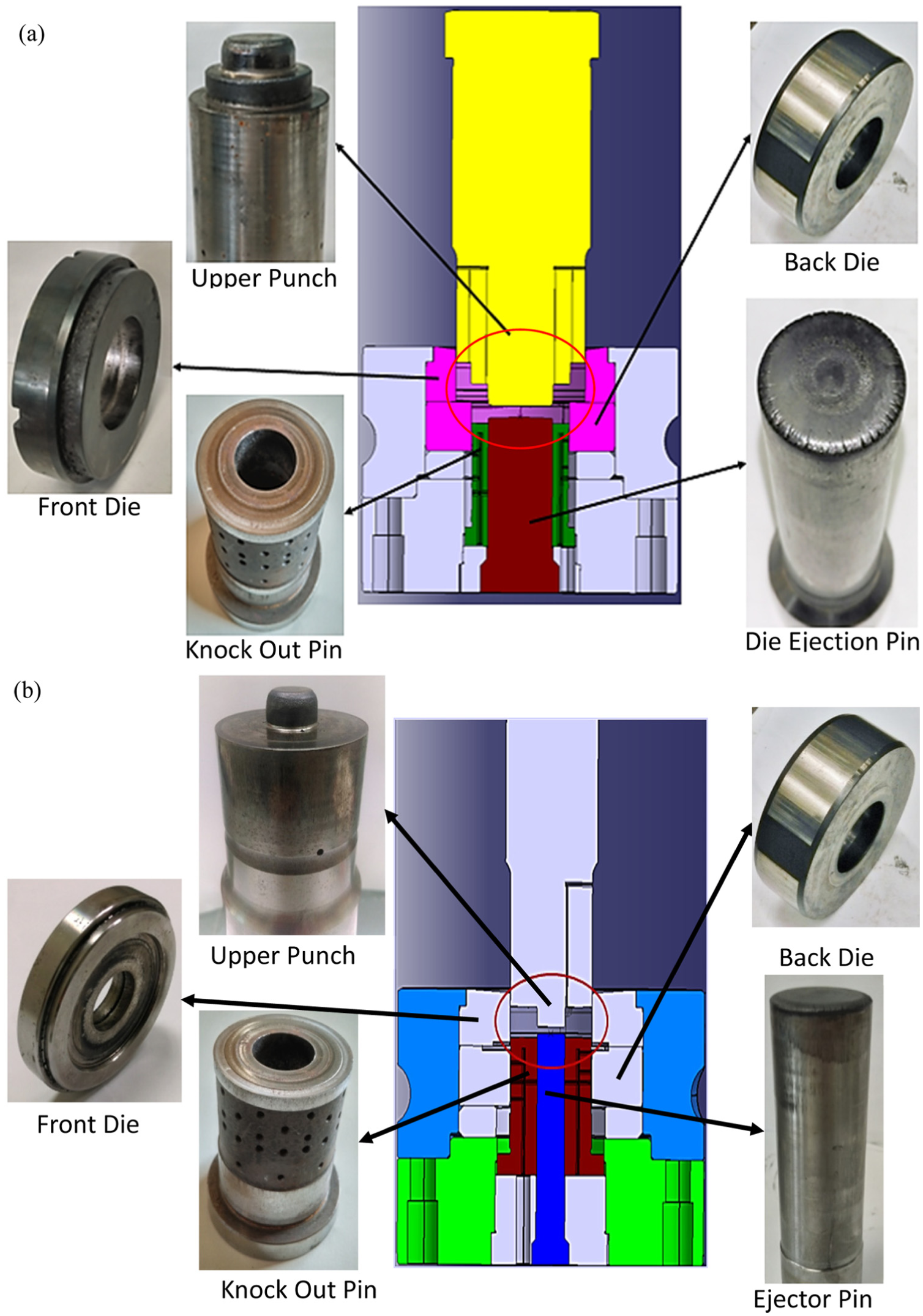
Tooling designs for (a) type A and (b) type B.
Deformation mechanism
Forging simulation of type A/type B
The plastic deformation at was simulated using commercial FE software, DEFORM 2D/3D. The platform is an ASUS X550V. The flow stress information of SUJ2 (AISI 52100) was adopted directly from the DEFORM database. The magnitude of the friction factor prevailing at the die/billet interface is using the constant shear model of 0.25 for the well lubricated case. 24 The forging temperature of the billet is initially set up to 1150 °C. Figure 6(a) and (b) illustrates the schematic simulation for upsetting and FF processes for type A and type B, respectively. Due to the large deformation occurring in the FF processes, the FEM mesh deformation severely and automatic remesh procedure is routinely used to complete the simulation. Furthermore, the metal flow pattern can be visualized via the developed function of flow net. As shown is the effective stress for both geometries. Type A is designed with a stepped configuration such that the upper punch has a larger height with two annular, stepped geometry. On the other hand, type B has smaller height with only one inside diameter. The simulated maximum principal stress is +143/–651 MPa and +110/–538 MPa, respectively. In addition, the simulated forging load is 67.9/57.2 ton. The reason for the higher effective stress and forging load as experienced by type A is mainly attributed to the higher deformation distance and larger projected area.
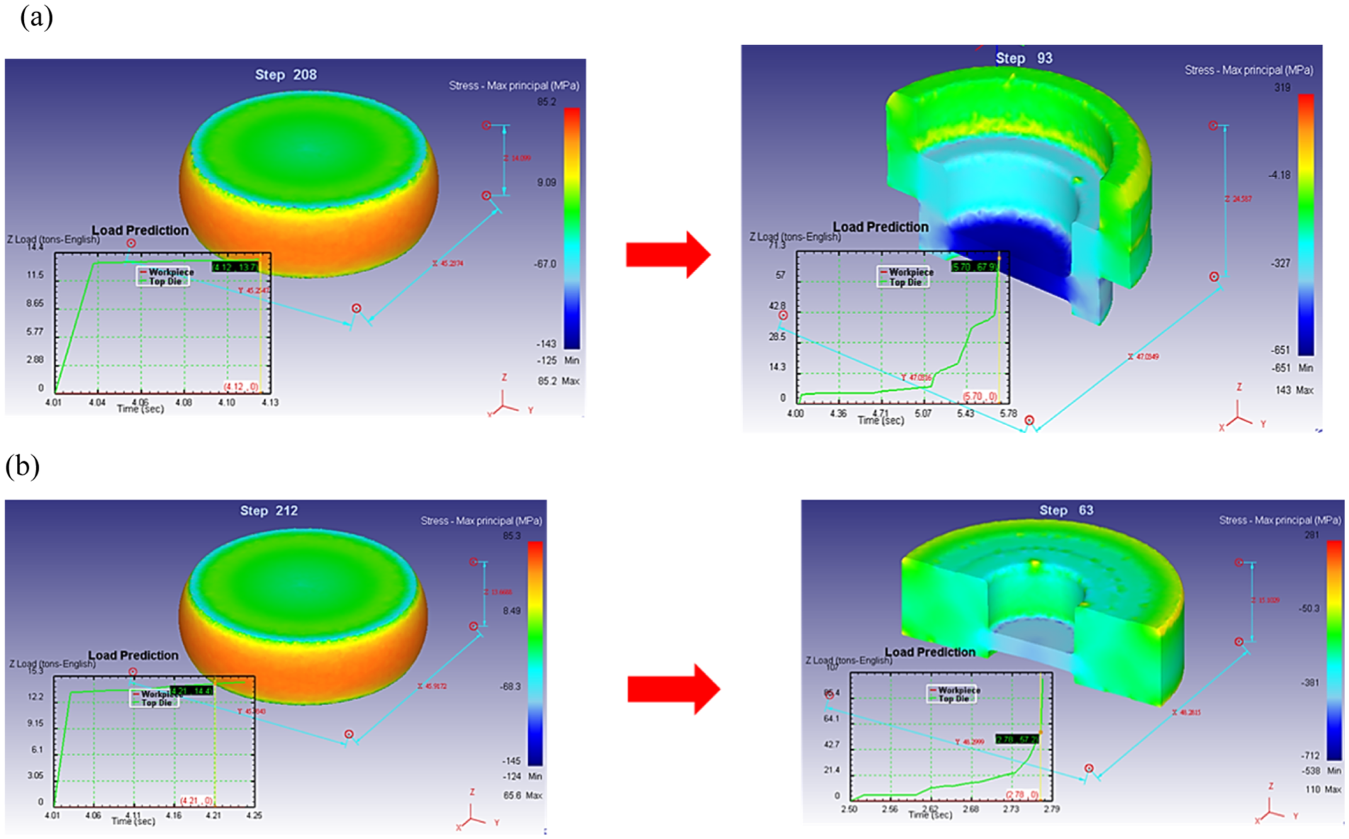
Schematic diagrams of simulations for upsetting and finish forging processes for configurations of (a) type A and (b) type B.
Effect of billet weight (type A) on the impact of material filling and forging load
Figure 7(a) shows the effect of billet weight on the impact of material filling and forging load after completion of the FF. The FF process is simulated with the different weights of billet in the FF process. The maximum forging loads required as well as the material filling of corner radius are primarily predicted to determine the suitable forging press capacity and parameters. Different billet material weight and related different forming parameters are shown in Figure 7(a)–(f). There are a total of six billet weights is simulated as compared with the standard weight (std), namely, +2 g, +1 g, +0.5 g, −1 g, −2 g, respectively. The letter “g” stands for the unit of gram as compared with the standard weight. The simulations assume that all the forging conditions are exactly the same (temperature, forging speed, etc.) except the billet weight. The simulation results indicate that the higher of standard weight, the better filling status of radius. In the case of +1 g, the forming of radius can reach ∼0.5 mm, which is satisfactorily accepted in actual operation. On the other hand for the +2 g case, corner radius is smaller than 0.5 mm; however, over-filled flash can be numerically simulated in Figure 7(f). On the contrary, other cases of −1 g to +0.5 g are simulated to be not completely filled in FF and the corner radius lies in the range of 1–3 mm and above. The acceptable range for corner radius in the actual production is in the range of 0.5–1 mm.
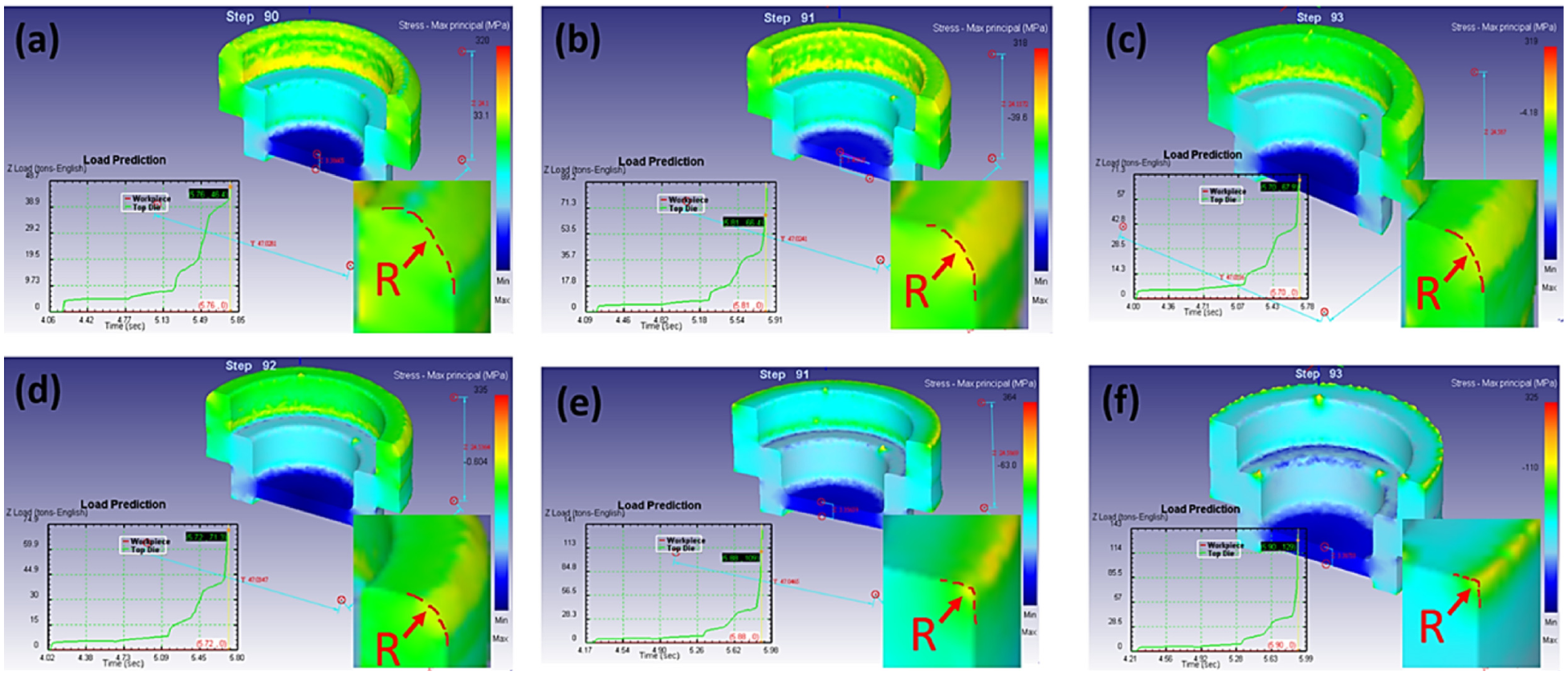
Effect of billet weight on the impact of material filling and forging load: (a) std −2 g, (b) std −1 g, (c) std, (d) std +0.5 g, (e) std +1 g, and (f) std +2 g.
As summarized in Table 2, the worst case scenario for the maximum radius and load are predicted to be about >3 and 129 ton for billet weight of −2 g and +2 g, respectively. In summary, the corner radius of the FF is simulated to be ranging between 0.5 and 3 mm, simply by changing a small amount difference of billet weight (–2 g vs +2 g). The forging load is also simulated to be drastically different for the above six cases such that almost threefold of forging load difference (129 ton vs 46.4 ton) can be predicted, based on the difference of billet weight of 4 g (–2 g vs +2 g).
Simulation results for the effect of billet weight for type A forging (punch radius used is R2.0 mm).
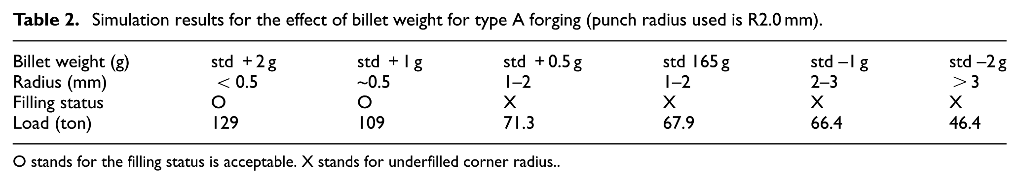
O stands for the filling status is acceptable. X stands for underfilled corner radius.
Combined effect of punch radius (R0.5 and R2.0 mm) and billet weight (–1 g, std, +1 g) on the impact of material flow
From the simulation result, the deformation of metal flow and the forming progression of the forging can be simulated and compared. In the FF, effect of punch radius (R0.5 and R2.0 mm) and billet weight (std −1 g, std, std +1 g) on the impact of material flow is presented in Figure 8. The red arrows indicate the colliding flow which represent the defect formation whereas the black arrows represent the relatively defect-free forming. The simulation assumed all the forging conditions are exactly the same (temperature, forging speed, etc.) except the billet weight and different radii of upper punch. In the warm forging process, with upper punch moves downwardly, the deformation resistance increases and ultimately, the complicated 3D states of stress and strain can be predicted in the FF parts. At the upper punch radius of R0.5 mm, the upper row from left to right shows the sequentially forming of different billet weights (std −1 g, std, std +1 g), the red arrow indicates the colliding flow and the resultant defect formation for all three cases, irrespective of billet weight difference. In contrast, due to the modified punch radius of R2.0 mm, the defect only occurs at the billet weight of std −1 g. For the case of larger billet weight (std and std +1 g), the relatively smooth material flows are simulated and the black arrow indicates the good forming condition. Table 3 displays the numerical results of the filling status, load and defect situation. The simulation results indicate that the higher of billet weight, the better filling status of corner radius. In the case of punch radius R0.5 mm, the forming of corner radius is in the range of 1–3 mm and the forming defect exists in the specific location of IR wall due to existence of strongly colliding flow. In contrast, relaxing the design of punch radius to R2.0 mm for the cases of billet weight (std, std +1 g) are completely forming without the existence of any defect in IR wall and the corner radius in FF ranging from 1.5 to 0.5 mm.
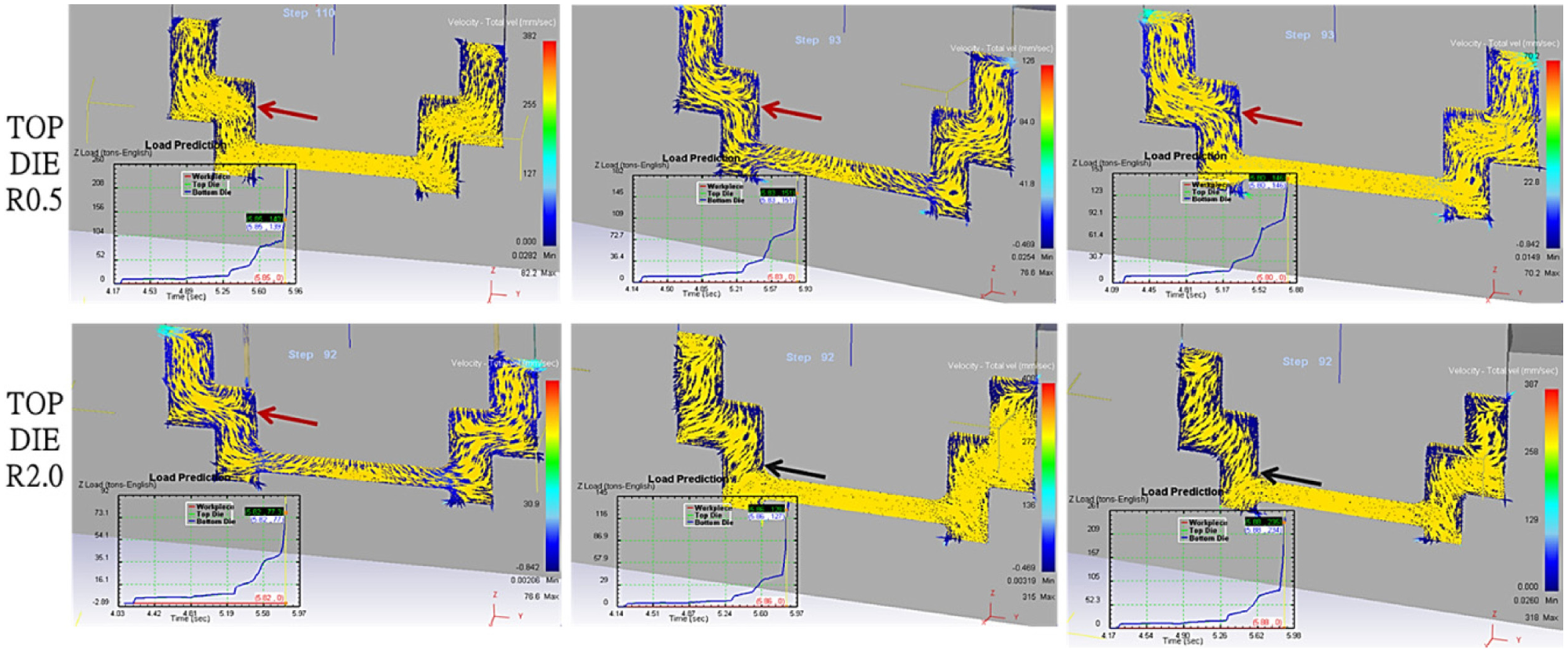
Effect of punch radius (R0.5 and R2.0) and billet weight on the impact of material flow. The red arrows indicate the colliding flow which represent the defect formation and black arrows represent the smooth flow pattern during the forging process.
Numerical results for type A punch radius effect (R0.5, R2.0 mm).
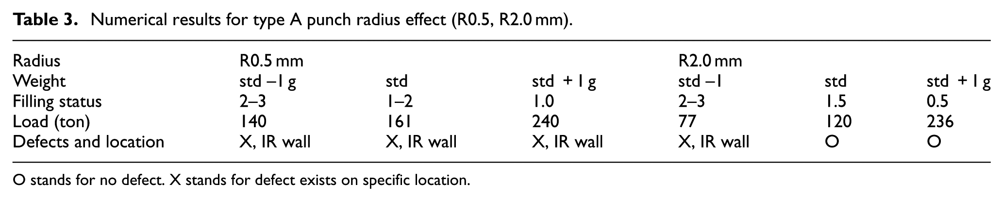
O stands for no defect. X stands for defect exists on specific location.
Analysis of the typical defects for type A forgings and possible mechanism
The investigated MSWF process in this study was used to manufacture the FF of DGBBs. To carry out the experimental investigation, the various defects of the forged SUJ2 bearing are performed and presented in Figure 9. Figure 9(a) shows the good FF product can be accepted for later post-machining processes. However, the lapping defect in Figure 9(b) demonstrates that a diagonally oriented crack of millimeter in width, which is structurally unacceptable and need to be removed. The underfill (R > 2 mm) defect of corner radius is primarily attributed to the uneven material flow is shown in Figure 9(c). Due to asymmetric forging such that the material underfill and overflow can be experimentally observed on the two opposite sides of the FF parts due to volume constancy. Figure 9(d) shows asymmetrical loading and resultant flash (overflow) on one side and underfill on the other side
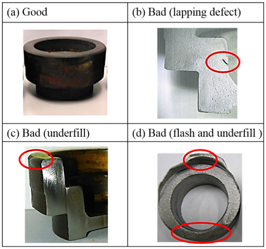
Various defects occurred during the actual forging process: (a) good, (b) lapping defect, (c) underfill (R > 2 mm) defect, and (d) asymmetrical loading and resultant flash on one side and underfill on the other side.
Experimental investigation for type B MSWF process
Effect of relief angle of KOP on the corner radius
Another configuration of type B (pancaked) was carried out and the primary forging defect is lack of filling (underfill) at the corner radius of lower outer radius (OR). Since mold design plays a key role in forging product, it is straightforward to investigate the geometry of KOP in FF. As shown in Figure 10, the corresponding die section for the underfill of corner radius is indicated in red circle and the effect of relief angle of KOP (θ = 0° and 2°) was experimentally and numerically examined. Similarly, there are 54 holes of 2 mm diameter are specially arranged at the circumference of KOP for the effective cooling fluid circulation. By modifying the tooling of knock out (KO) at two different relief angles (θ = 0° and 2°), the impact of filling status of the corner radius of lower OR was investigated, as shown in Figure 11. In the FF process of originally designed relief angle (KO = 0°), Figure 11(a) demonstrates that the FF product with the corner radius is bigger than 1.5 mm, which is unacceptable for later machining operation. In contrast, the modified relief angle (KO = 2°) provides a taper section and thus promotes the better material flow as well as smaller corner radius less than 1.0 mm, as shown in Figure 11(b). The specification for the corner radius in the actual production is set in the range of 0.5–1 mm for successful post-processing operations.
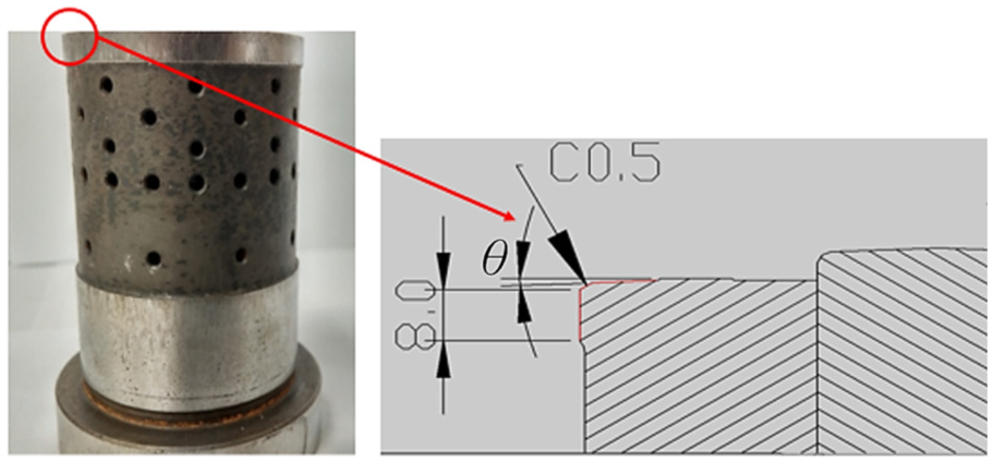
Effect of relief angle of KOP (θ = 0° and 2°).
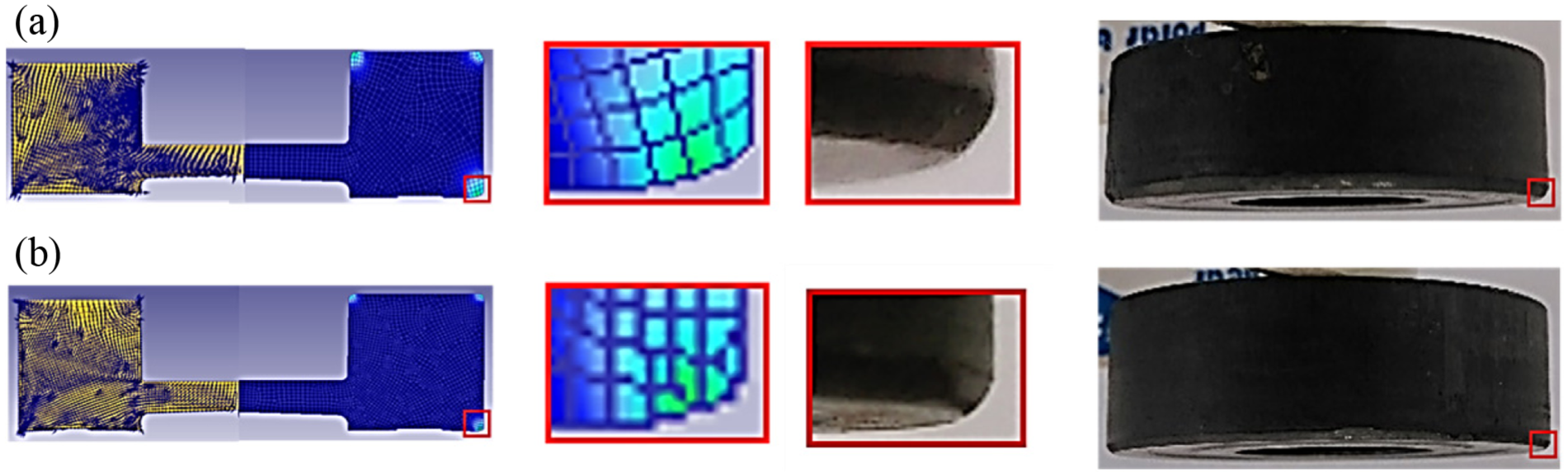
Simulations and experiments on the effect of relief angle of KOP (θ = 0 and 2°): (a) original relief angle of KOP (θ = 0) and (b) modified relief angle of KOP (θ = 2°).
Combined effect of KO relief angle under different cooling conditions
As shown in Figure 12(a), the combined effect of KO relief angle under different cooling conditions was experimentally investigated while the same billet length of 25.6 mm (corresponds to the weight of std +1 g). on the contrary, the left and right columns illustrate the actual forging results of KO relief angle 0° and 2°, respectively, in Figure 12(a). In both KO relief angles, three different volume flowrate of cooling fluid (19.5, 15.3, 11.3 L/min) was also investigated systematically as shown from top to bottom. The experimental results of cooling fluid flowrate versus load distribution and corner radius filling was presented in Figure 12(b); all tested billets are 25.6 mm in height and 28 mm in diameter. Based on the experimental results, the linear fitting curve between the maximum forging load and the cooling fluid flowrate can be empirically plotted. In the case of KO (0°), the maximum forging load is ranging from 208.6 to 209.8 ton while the KO (2°) achieves a relatively small forging load in the range of 206.6–208 ton. However, the difference in the maximum forging load is negligibly small and the modified design can effectively improve the defect occurrence without disrupting other forging parameters. Similarly, in terms of maximum forging load, effect of cooling flowrate was also experimentally found to be small and all the measured forging loads are within 1% difference. However, the modified relief angle can produce the forgings with acceptable corner radius (R ≤ 1 mm), irrespective of cooling flowrate.
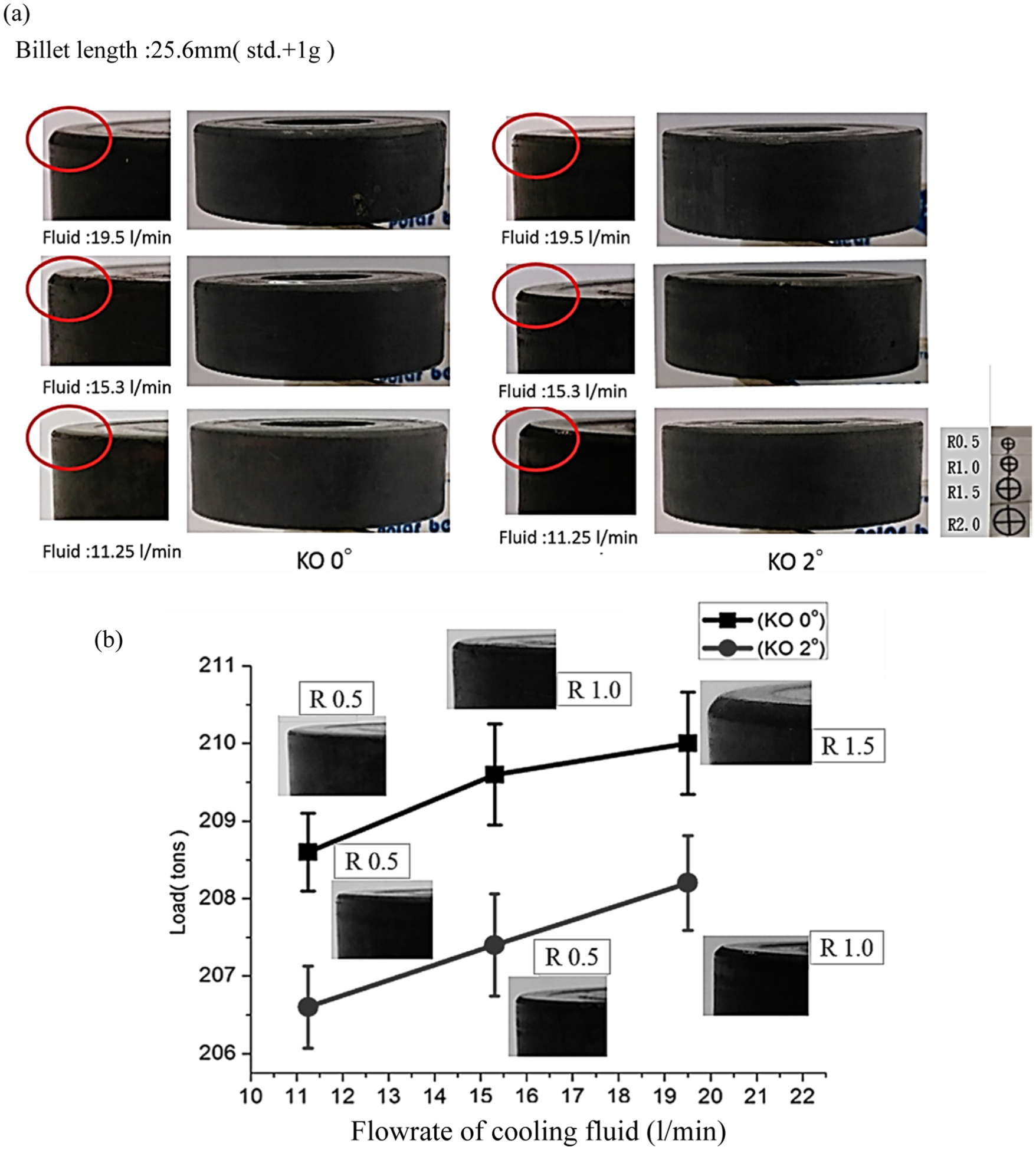
Effect of KO relief angle, cooling fluid flowrate versus corner radius filling and maximum forging load: (a) actual forging results showing the corner radius for various forging parameters and (b) effect of cooling fluid flowrate on the maximum forging load and material filling of corner radius.
Effect of billet length under different cooling conditions
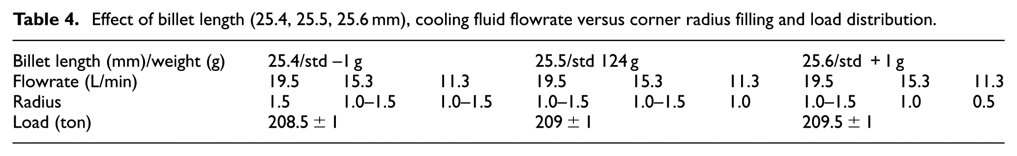
In actual forging operations, the commonly implemented quality control method is utilizing the sheared billet length and weight. How to the set the upper and lower control limit is the main focus of this study. Figure 13 shows the effect of three billet lengths (25.4, 25.5, 25.6 mm) under various cooling fluid flowrate and the impact on corner radius filling and forging load. The relief angle for the study is set on KO 0°. As shown in Figure 13(a), for cases of the billet lengths of 25.4 and 25.5 mm (corresponds to billet weight of std −1 g and std), the cooling flowrate has a minimal impact on the corner radius filling, all cases resulting to the corner radius of 1.0–1.5 mm. Figure 13(b) and Table 4 summarize the effect of billet length (25.4, 25.5, 25.6 mm) and cooling fluid flowrate on the maximum forging load and filling of corner radius. The relative change of forging load was found to be ranging from 207 to 210 ton. It is noted that for the case of 25.4 mm billet length, the filling of corner radius is incomplete (R > 1 mm) due to volume constancy (insufficient billet weight). On the other hand for the case of 25.4 mm billet length, the cooling flowrate of 19.5 L/min will produce unstable filling of corner radius (1.0–1.5 mm), which should be avoided in the actual mass production. Therefore, the operating window for the most stable production is adopting the 25.6 mm billet length, which corresponds to the 0.8% extra billet weight, satisfactory corner radius can be forged while other forging parameters are relatively unchanged.
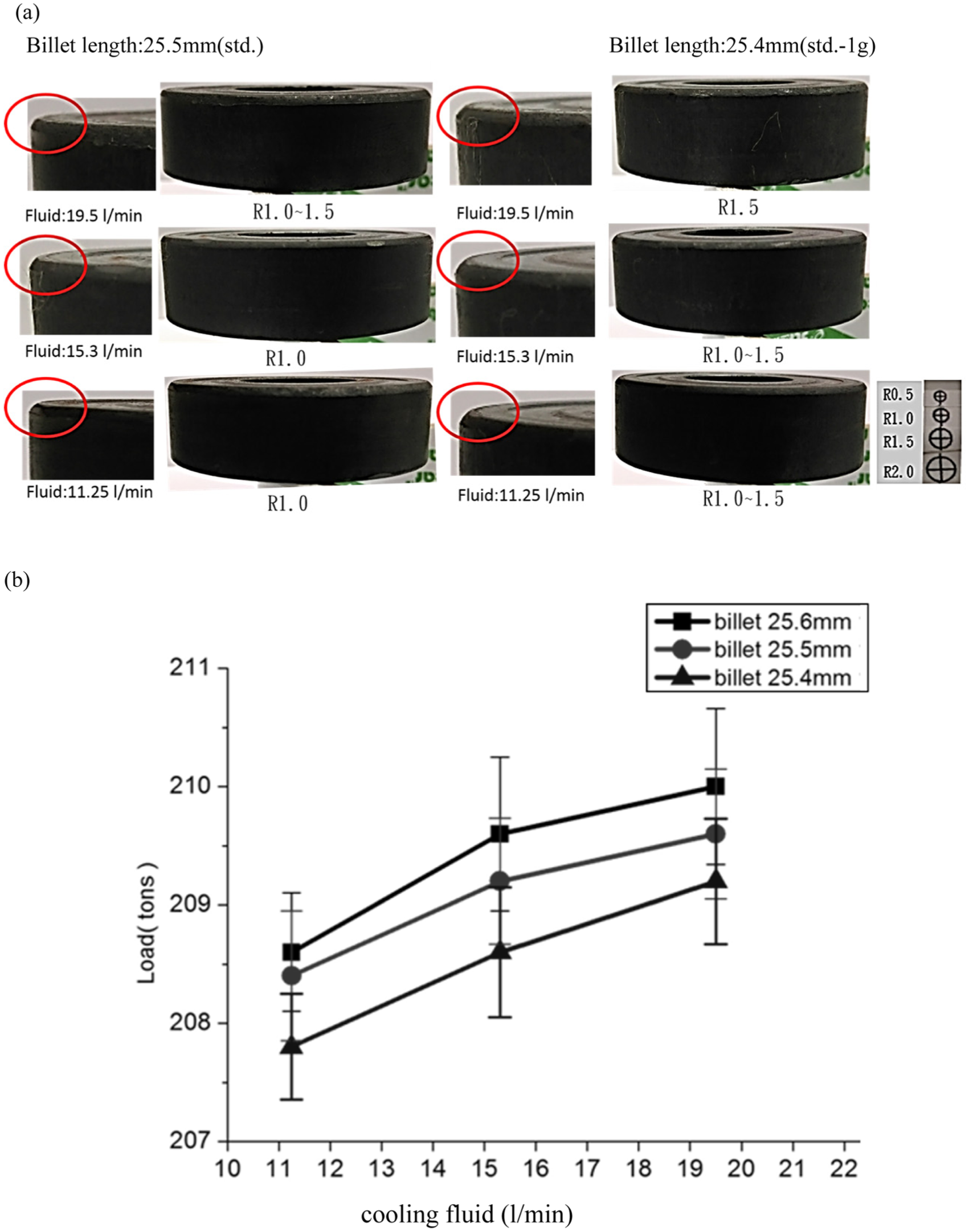
Effect of billet length (25.4, 25.5, 25.6 mm) and cooling fluid flowrate versus corner radius filling and maximum forging load: (a) billet length (25.4, 25.5 mm) and the impact on the corner radius filling and (b) billet length (25.4, 25.5, 25.6 mm) and cooling fluid flowrate versus maximum forging load.
Effect of billet length (25.4, 25.5, 25.6 mm), cooling fluid flowrate versus corner radius filling and load distribution.
Microstructural analysis and discussion of type A/type B FF results
Figures 14 and 15 show a metallographic photo of the type A/type B, with the focus of the deformation mechanism and the impact on the AGS. After forging, type A varies slightly from 5.93 to 7.65 μm, which can be mainly attributed to the difference of deformation strain as experienced in various sections during the forming process. On the other hand, type B shows a relatively uniform grain size and the grain size varies from 7.82 to 8.18 μm. In the process of type A forming, there are ring-shaped geometry in the junction of IR and OR. On the contrary, the type B forming has no sharp configuration in the FF and therefore, type B forgings experience comparatively uniform strain such that the grain size is more smooth than the type A design.
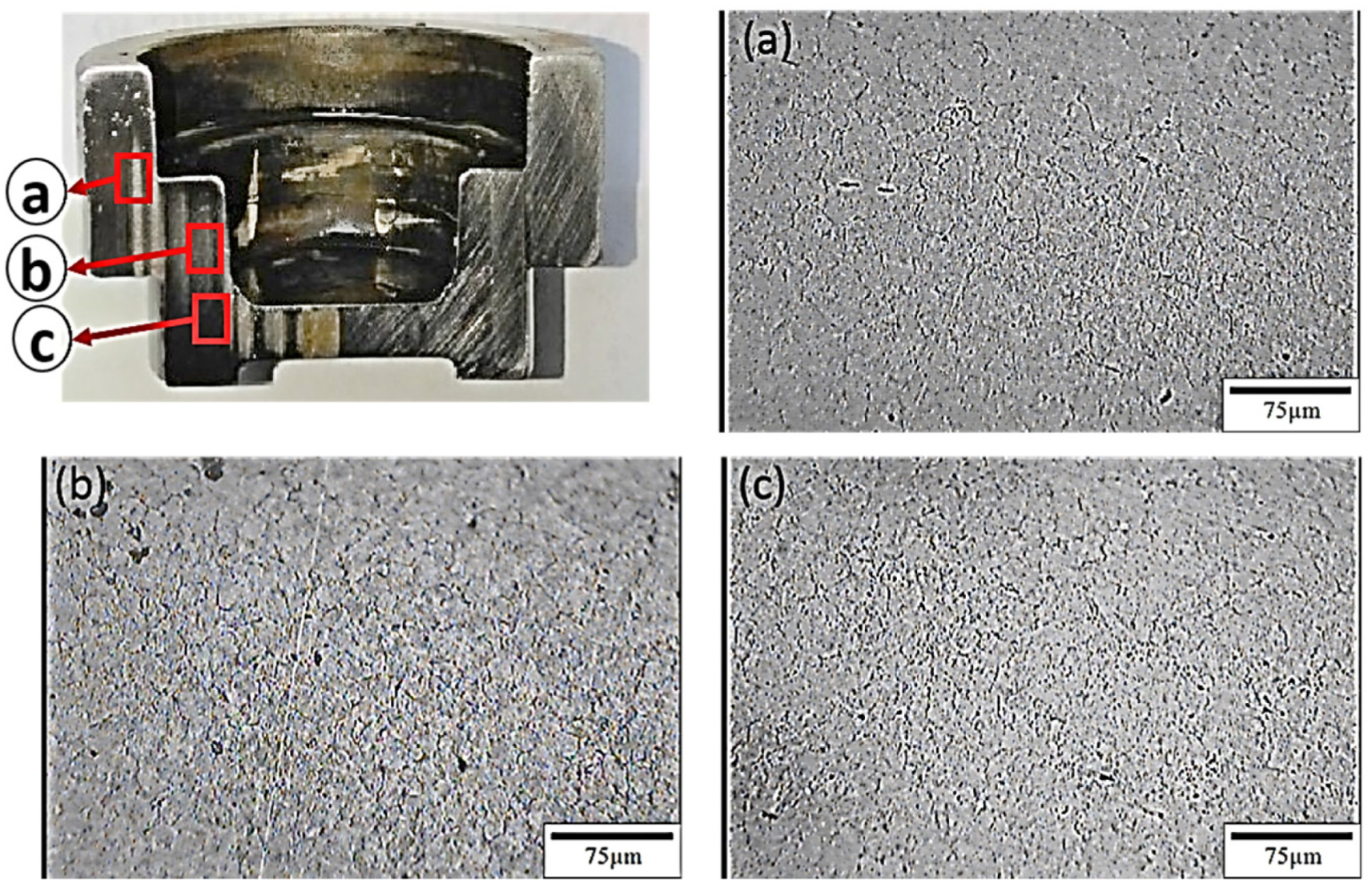
Metallographic photos and average grain size (AGS) of the type A: (a) point 1 (AGS of 7.50 μm), (b) point 2 (AGS of 5.93 μm), and (c) point 3 (AGS of 7.65 μm).
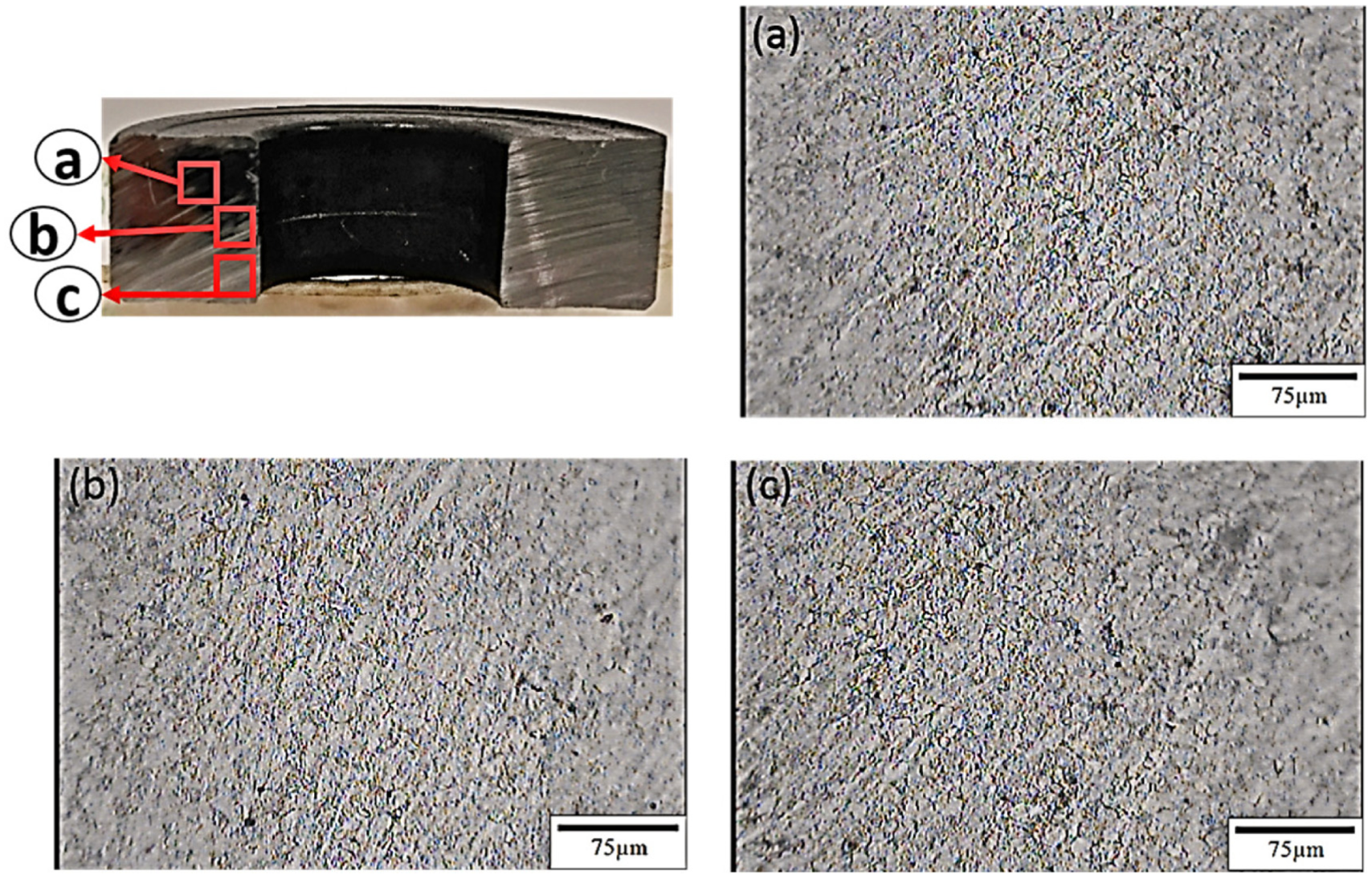
Metallographic photos of the type B: (a) point 1 (AGS of 8.18 μm), (b) point 2 (AGS of 7.82 μm), and (c) point 3 (AGS of 8.00 μm).
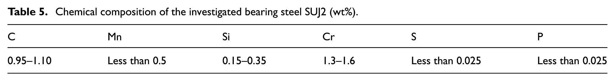
In order to further validate the structural integrity and chemical composition of FF, two forming processes were selected and the sample pieces were axially sectioned for the investigation of energy dispersive X-ray spectrometry analysis (EDS). The surface was initially ground with sand papers from a mesh size of 100–1000. The results are presented of EDS composition analysis of FF in Figure 16 for the type A and type B. Specifically, the ingredients of Cr (chromium), Fe (iron), and a small amount of C (carbon) were identified since these are the primary constituents of the bearing steel and possible contamination from the forging process was also evaluated. The FF of type A as indicated revealed that iron is abundant (97.4 wt%), while other compositions of chromium and carbon are identified as 1.59 wt% and 1.01 wt%. In comparison, type B is presented the main ingredients for the iron/chromium/carbon are 97.45 wt%/1.47 wt%/1.08 wt%, respectively. Compared with the raw material SUJ2 in Table 5, the chemical composition of chromium is almost intact in the range of 1.3–1.6 wt%. Similar trend can be concluded for the composition of carbon and iron, indicating the warm forging process is well controlled and free from contamination from other chemical composition.
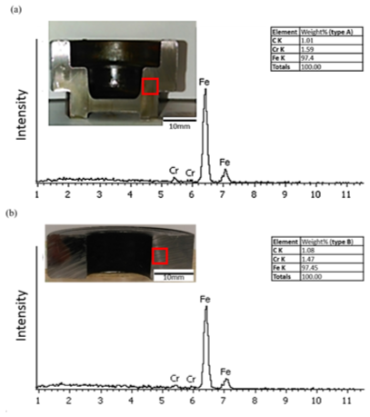
EDS composition analysis of finish forging: (a) EDS composition of type A and (b) EDS composition of type B.
Chemical composition of the investigated bearing steel SUJ2 (wt%).
Conclusion
In this study, the deformation mechanism of MSWF process for the tooling design of the IR/OR DGBB for two distinctive configurations of type A (stepped) and type B (pancaked) is analyzed numerically and experimentally. Both numerical and experimental investigations were systematically studied, particularly in the geometry of punch and knock pin at the FF stage. In addition, the dimension variation of billet weight and the forging temperature difference as impacted by the lubricating fluid are also investigated. In summary, the following results are presented:
The FF process is simulated using SUJ2 of bearing steels. In the upsetting processes of type A and type B design, the forging temperature is initially set up to 1150 °C. The upsetting ratio and degree of upsetting are theoretically calculated as
In type A design of different billet weights, the corner radius of the FF is simulated to be ranging between 0.5 and 3 mm, simply by changing a small amount difference of billet weight (–2 g vs +2 g). The forging load is also simulated to be drastically different (129 ton vs 46.4 ton), based on the difference of billet weight as small as 4 g (–2 g vs +2 g). On the other hand, cases of smaller billet weight (–1 g to +0.5 g) are simulated to be not completely filled in FF and the corner radius lies in the range of 1–3 mm and above. The acceptable range for corner radius in the actual production is in the range of 0.5 and 1 mm, which corresponds to the proper billet weight window (+1 g, +2 g).
Effect of punch radius (R0.5 mm, R2.0 mm) in type A design shows that smaller punch radius (R0.5 mm) will restrict the forming of corner radius (in the unacceptable range of 1–3 mm) and promotes the strongly colliding flow and forming defect in the specific location of IR. In contrast, relaxing the design of punch radius to R2.0 mm for the cases of billet weight (std +1 g) can promote completely forming of corner radius in FF (ranging from 1.5 to 0.5 mm) without the existence of any defect in IR wall.
For the type B design, the relative change of forging load was found to be modestly ranging from 207 to 210 ton due to cooling fluid volume variation between 11.3 and 19.5 L/min. On the other hand, the billet weight is found to be of crucial influence and the operating window for the most stable production is adopting the case of +1 g billet weight (25.6 mm billet length), which corresponds to the 0.8% extra billet weight such that satisfactory corner radius (R < 1.0 mm) can be successfully forged.
There is a pronounced defect due to asymmetric loading, which will cause a severe consequence for both product and tooling of upper punch. The FF defects are primarily attributed to asymmetric forging such that the material underfill and overflow can be simultaneously observed on the two opposite sides of the FF parts. The consequence of asymmetric loading will inevitably result in an increase of 40% punch effective stress is simulated (1080 MPa vs 619 MPa). Furthermore, the experimental consequence of this asymmetric loading will cause the pre-matured and excessive wear profile of punch, as observed experimentally.
Footnotes
Acknowledgements
The last author would like to acknowledge the partial support by Wen-Chieh Chen of TPI company’s General Manager, Taoyuan City, Taiwan. To us thank you for your scholarship internship opportunities to better understand the ecology and industry–university cooperation.
Declaration of conflicting interests
The author(s) declared no potential conflicts of interest with respect to the research, authorship, and/or publication of this article.
Funding
The author(s) disclosed receipt of the following financial support for the research, authorship, and/or publication of this article: This study was financially supported by the Tung Pei Industrial Co., Ltd.