
Abstract
Mobile robots are widely used in many applications, such as transportation, military domain, searching, guidance, rescue, hazard detection, and carpet cleaning. Because mobile robots usually carry limited power sources, such as batteries, energy saving is an important concern. In particular, differential wheeled mobile robots that have two independently movable wheels are popular because of relatively low mechanical complexity to achieve three-dimensional motion on a ground. This article presents a new wheeled device with a redundant drive system which consists of three independently movable actuators and two planetary gears to connect the actuators to two wheels. The proposed system is able to continue its motion safely when one of the motors breaks down for some causes and also able to operate over a longer period of time due to energy saving consumption property. Experimental results show that the proposed method is effective in saving energy approximately by 20.45% for linear motion and 13.05% for circular motion compared to a conventional one.
Introduction
Mobile robots are widely used in many different applications, such as transportation, military domain, searching, guidance, rescue, hazard detection, and carpet cleaning.1–3 Robots usually carry limited power sources, and it is generally impossible to add new supply of energy while working, so energy conservation is an important concern for mobile robots.4–8
Nowadays, Japan’s declining birthrate and aging population are having a profound impact on the society, economy, and culture. So, an essential task for Japan society is the improvement of the quality of life for the elderly and disabled people and to support their self-movement. 9 The need of personal mobility supporting personal movement for the aging society is increasing.
Wheeled mobile robots (WMRs) are popular because of relatively low mechanical complexity and energy consumption. In last few decades, many researches have been conducted for energy saving in mobile robots.6,10–16 WMRs usually have many components, such as sensors, batteries, motors, controllers, and motor drivers. There are several ways to achieve energy saving such as improving the power efficiency of motor power supply and using energy-efficient motors and energy-minimizing control.13,17,18
A differential wheeled mobile robot (DWMR) involves two independently driven wheels on a common axis. 1 The robot moves straight forward or backward when the wheels rotate at the same speed, and the robot follows a curved path along the arc of an instantaneous circle, around the instantaneous center of rotation (ICR) when one wheel rotates faster than the other. 1 The robot turns about the midpoint of the two driving wheels when both wheels rotate at the same velocity in opposite directions. When one of the motors breaks down or has damage for some causes, the robot rolls around the wheel which is connected to the damaged motor. Eventually, there will be a risk of the passenger’s life because the passenger cannot continue the motion.
Energy saving is also a considerable topic in mobile robots for increasing the operating time using the same battery capacity. Duleba and Sasiadek 19 discussed a modification of the Newton algorithm applied to nonholonomic motion planning for energy optimization. However, the amount of consumed energy cannot be estimated. Ueno et al. 15 proposed a differential drive steer system for the caster drive wheel of an omni-directional mobile robot. However, the system is expensive because they used two motors for each wheel. As mobility demands limited independent power sources, energy management is the key factor to complete tasks. To overcome this, our research group designs a wheeled system consisting of a redundant drive system to continue its motion safely when one of the motors breaks down for some causes.20,21 In addition, the redundancy provides the use of each motor at its efficient operating condition. The system uses three motors and two planetary gear systems, which have high transmission efficiency and durability for high power.
Main contribution of this article is as follows: a new design of WMRs is presented in this article to guarantee a secure motion even when one drive system does not work. In addition, its effectiveness for energy saving is analyzed to increase the operating time using the limited battery capacity. Furthermore, simulation and experimental results demonstrate that the proposed method is practically effective. The experimental results in this article show that the method is effective in saving energy approximately by 20.45% for linear motion and 13.05% for circular motion compared to a conventional drive system.
This article is organized as follows. A description of redundant wheeled drive system is included in section “Redundant wheeled drive system.” Section “Controller design” presents the controller design for redundant drive system. Section “Simulation and experimental results” presents the experimental results. Section “Conclusion” provides concluding remarks.
Redundant wheeled drive system
System structure
In general, a DWMR has two driving wheels which are attached to both sides of the device, and each wheel is driven by one motor independently. In order to realize a redundant wheeled drive system, we designed a wheeled system consisting of a redundant drive, as shown in Figures 1 and 2.

Redundant wheeled drive system.

Experimental device (backside).
The system has two drive wheels with three motors and two planetary gears, which have high transmission efficiency and durability for high power. As shown in Figure 1, motors 1 and 2 are connected to right and left wheels through each planetary gear. Motor 3 is connected to both right and left planetary gears, and it supplies power for both wheels. Planetary gears consist of a planetary carrier and an outer gear that revolve around a sun gear. In this system, the sun gear connects to motor 3, the outer gear connects to motors 1 and 2, and the planetary carrier connects to each wheel.
We assume that like personal mobility vehicle such as electrical wheelchairs, desired linear and angular velocities of the vehicle are given by operators. We further assume that when one motor breaks down, the operator once stops the system and switches the drive mode of into two-motor control mode. Thus, the singularity or instability matter during transition of the drive mode is not considered in this study and is left for future work.
Mobile robot dynamics
This section describes dynamic equations of the WMR. The robot has two identical rear wheels controlled by three independent motors, and two caster front wheels are used for stability. We assume that the sliding of wheels is negligible. This study considers a WMR in Figure 3. The model includes planetary gear property. The dynamics of the mobile robot is given as follows


where Mw, I,

Two-wheeled mobile robot.
The relationship between the linear velocity of the WMR,


where

where
Dynamical equations of the motors are given as follows

where
The motor dynamics of the right and left wheels are given as follows

where
From equations (1)–(8), we obtain the equation of motion of the WMR as follows

where M is the 3 × 3 inertia matrix, C is the 3 × 3 viscous friction matrix, and G is the 3 × 3 control input matrix, which are as follows


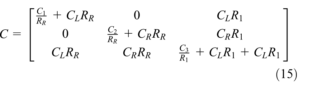
where
Controller design
Distribution controller
This study applies distribution and state feedback controllers to the WMR in Figure 2. Figure 4 shows the block diagram of the control system. The reference translational speed
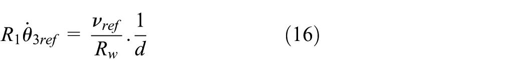
By substituting equation (3) into equation (16), we obtain the angular velocity

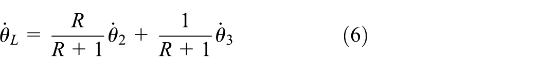
By substituting equation (17) into equations (5) and (6), we obtain the angular velocities

when
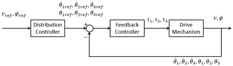
Block diagram of the control system.
State feedback controller
In this study, we assume that commercial motor controllers are based on PD control, and we apply the state feedback controller to the proposed WMR as the feedback controller. Feedback gains are obtained by the pole placement method. We consider the following controller

where

where

Simulation and experimental results
In this study, the authors verified the proposed method by means of simulation. 21 We experimentally applied the proposed method to a WMR, as shown in Figure 2. The control law in equation (19) was implemented using C# language on a laptop PC (OS: WINDOWS 8.1, CPU: 2.3 GHz) with sampling time of 50 ms. In addition, two optical encoders whose resolution is 0.352°/count are attached to motors 1 and 2, and an optical encoder whose resolution is 0.18°/count is attached to motor 3 to measure angular velocities of motors. A pulse counter board with two channels of 24-bit up/down counters and a Digital to Analog converter (DA) board with 16-bit resolution are used for control. Motor drivers are also used in a current control mode, which supplied electric current depending on the voltage commanded from the laptop PC to each motor.
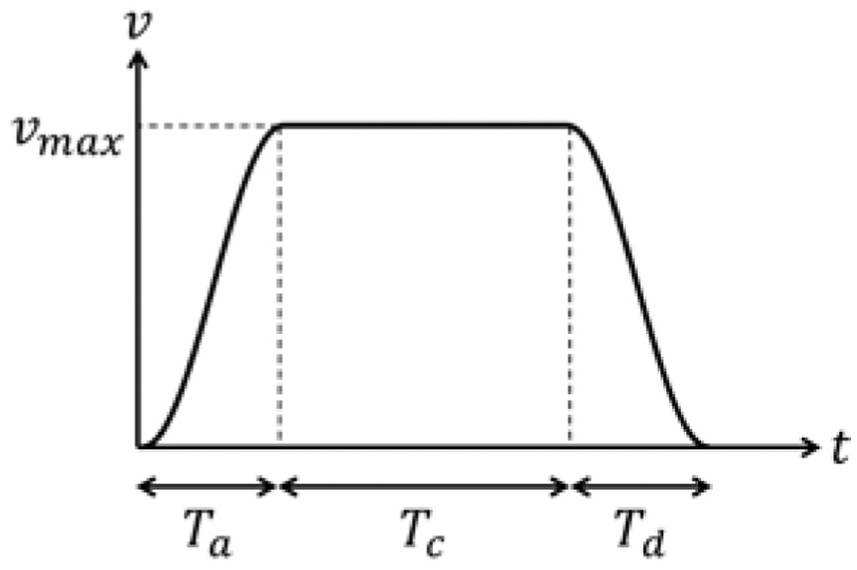
Figure 5 shows an S-shaped velocity profile used as a reference translation velocity of the WMR. The velocity


where
Dynamics parameters values.

S-shaped velocity profile.

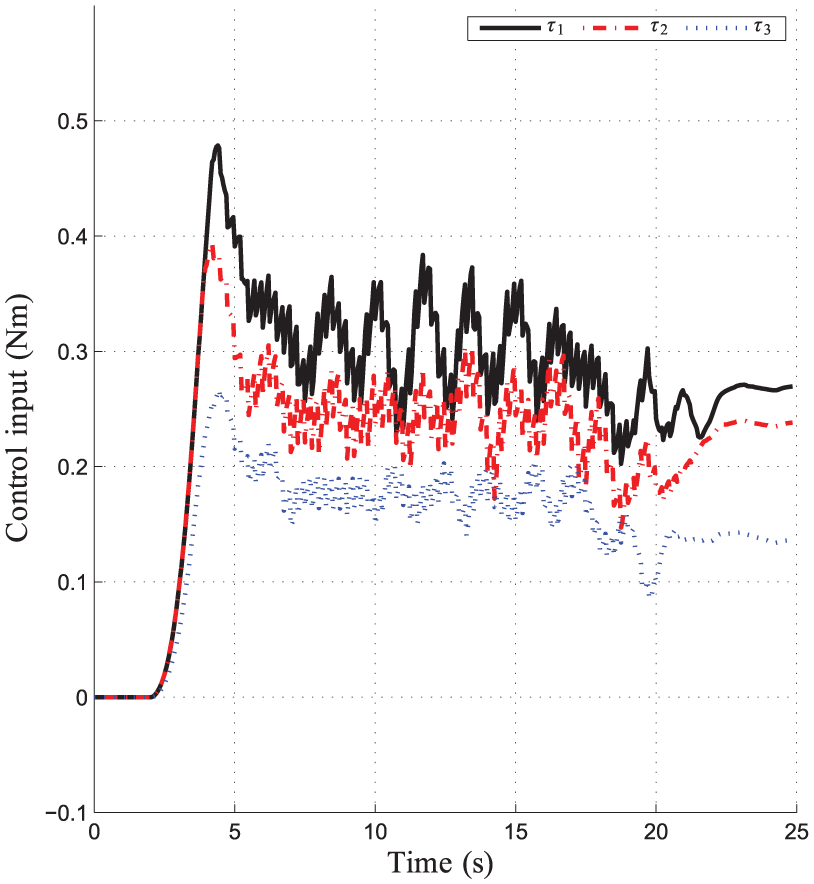
Control input of all motors

Control input of all motors (d = 1), the same profile is obtained for

Control input of all motors (d = 3.5), the same profile is obtained for

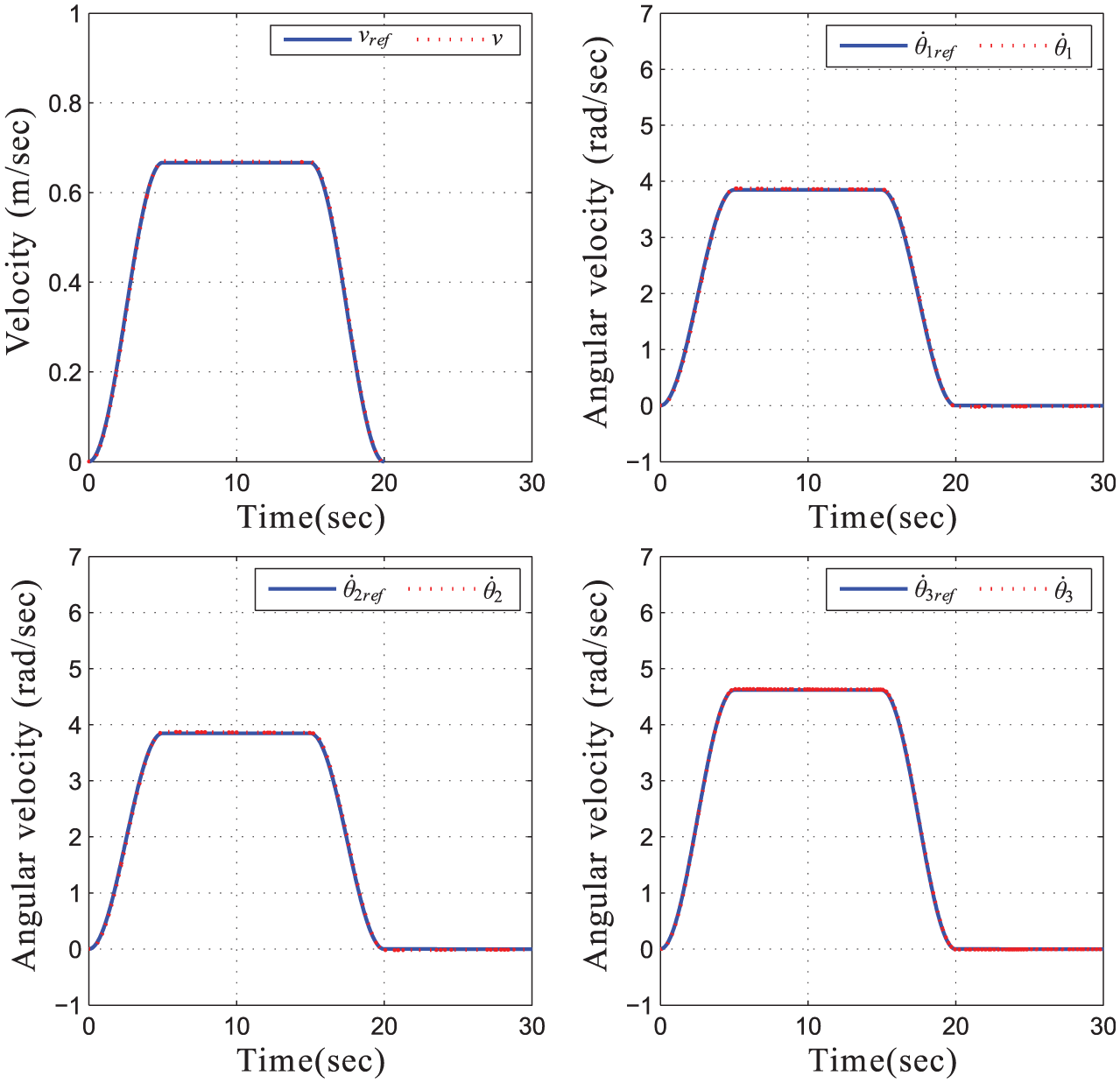
Simulation result

Simulation result (d = 1).
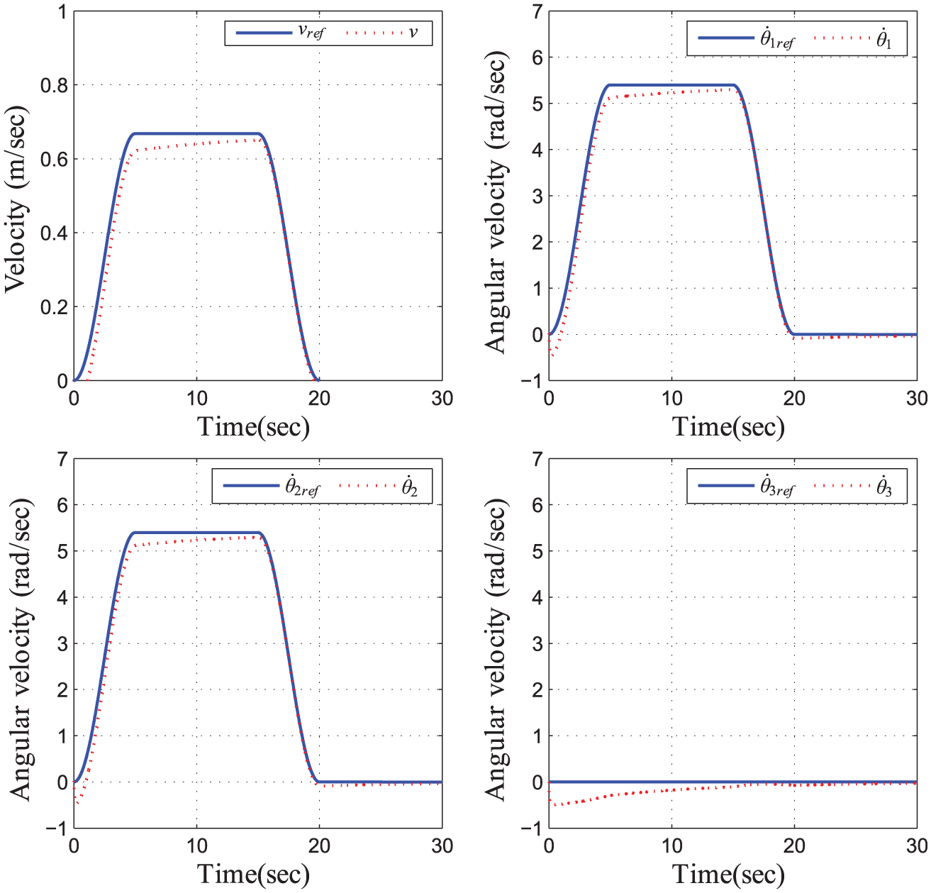
Simulation result (d = 3.5).

Simulation result for circular motion (d = 3.5).

Simulation result for linear and angular velocities for circular motion, as depicted in Figure 12.

Simulation result for tracking performance with off-trajectory initial conditions (d = 3.5).
Simulation result for tracking performance with off-trajectory initial conditions
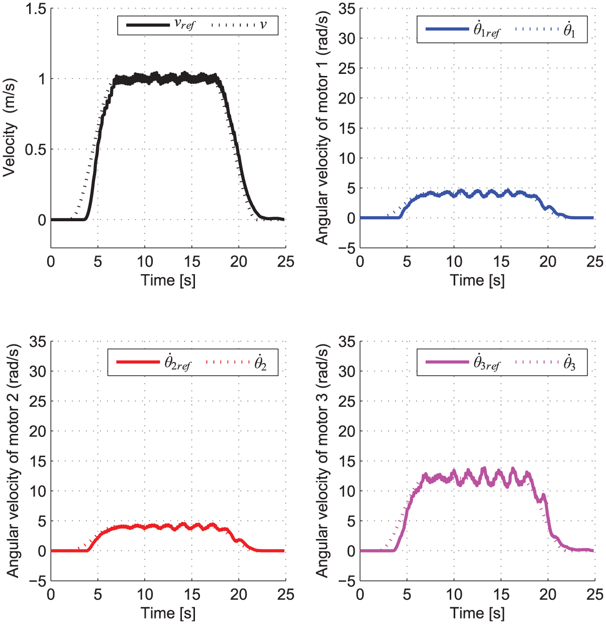
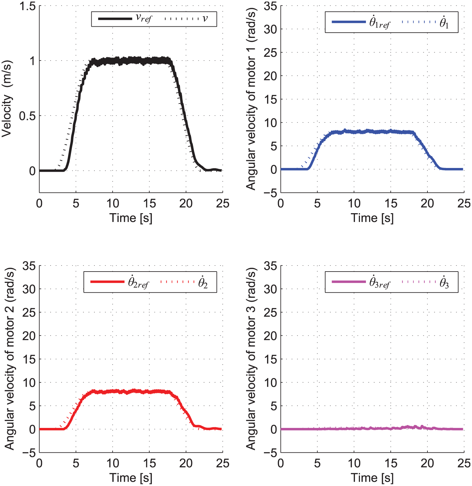
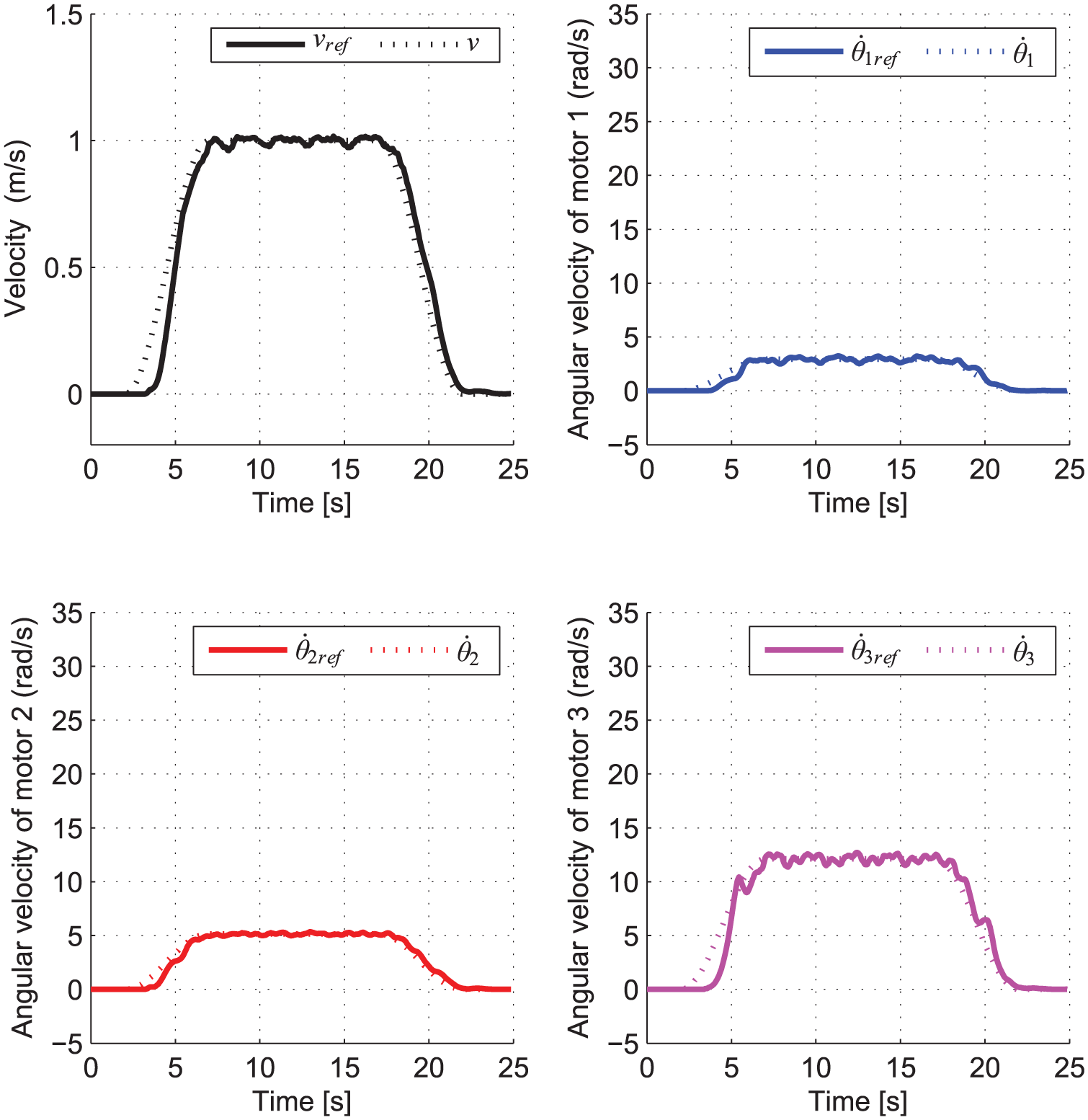
The feedback gains used in experimental are shown in Table 2, which are obtained by the pole placement method (poles are located at −2, −2, and −3 (1/s)). Figures 16–18 show the experimental results of the control input of each motor. Figures 19–21 show the experimental results of the translational speed and linear velocity of each motor. In Figure 21, when the value of
Experimental condition (controller gains).


Control input of all motors (d = 1), the same profile is obtained for
Control input of all motors (d = 2).

Control input of all motors (d = 100).

Experimental results (d = 1).
Experimental results (d = 2).
Experimental results (d = 100).

Experimental result for circular motion (d = 2).
Experimental results for linear and angular velocities for circular motion, as depicted in Figure 22.
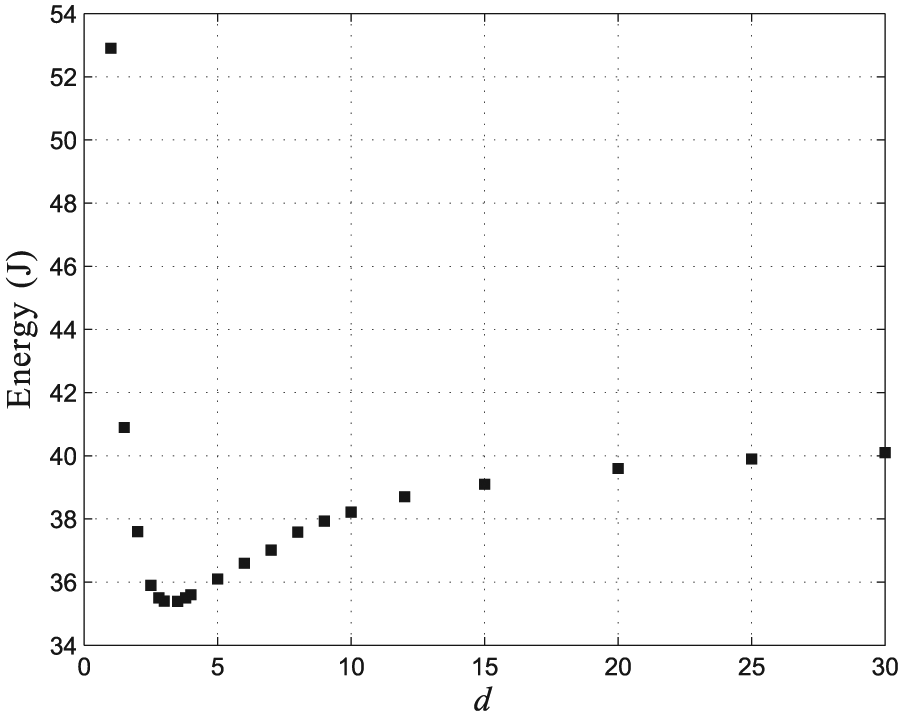
Energy consumption
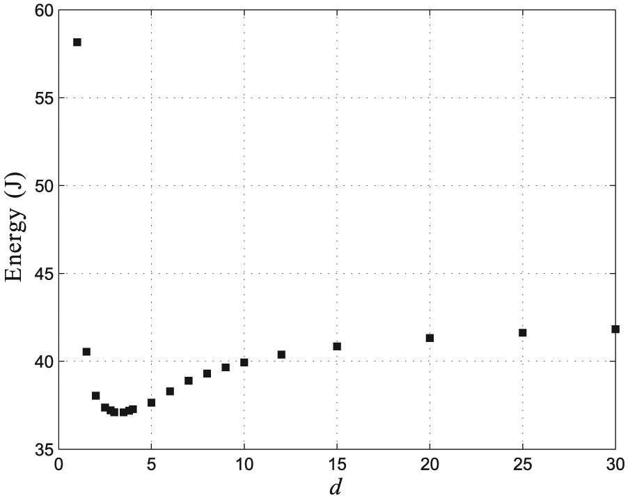
The WMR usually carries limited energy sources such as batteries. The battery capacity determines the operating time. Here, we consider the effectiveness of the proposed WMR for energy saving. Energy required for the motors is obtained by the following equation

where E is the total energy consumption. We verified different robot speeds in simulation, as shown in Figures 24–27. For all cases,
Total energy consumption for linear motion (robot speed = 0.668 m/s).

Total energy consumption for linear motion (robot speed = 1 m/s).
Total energy consumption for circular motion (robot speed = 0.668 m/s).

Total energy consumption for circular motion (robot speed = 1 m/s).

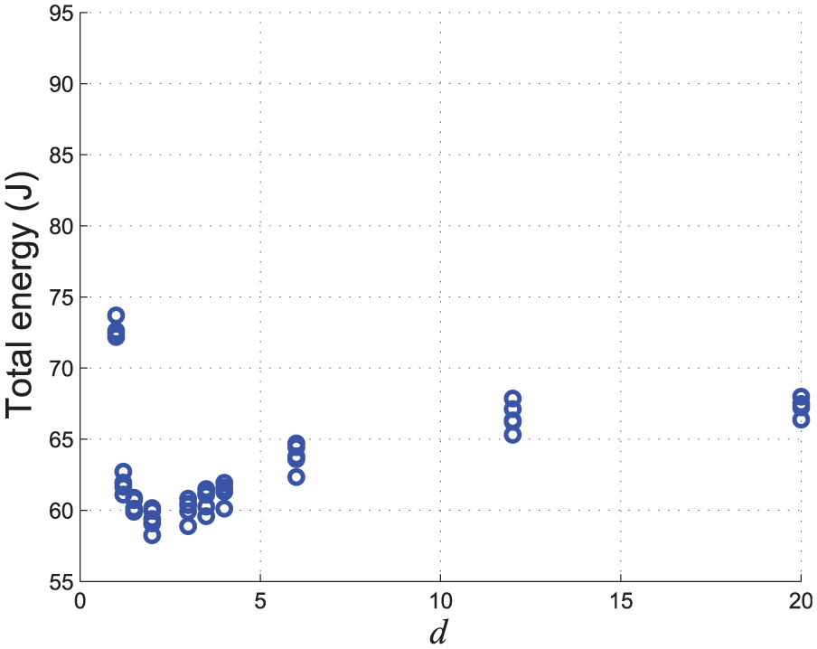
Total energy consumption for linear motion.
Total energy consumption for circular motion.

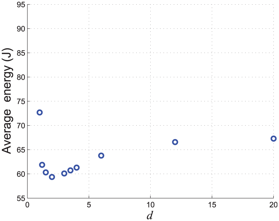
Average energy consumption for linear motion.
Average energy consumption for circular motion.
Conclusion
This article presents a new wheeled device with a redundant drive system to continue its motion safely when one of the motors breaks down for some causes. The proposed method also aims energy saving for a wheeled drive system. The distribution and state feedback controllers are applied for the wheeled drive system. The distribution controller creates the reference angular velocity of motors. Experiment was conducted to verify the effectiveness of the proposed method, and a distribution ratio
Footnotes
Academic Editor: Hamid Reza Shaker
Declaration of conflicting interests
The author(s) declared no potential conflicts of interest with respect to the research, authorship, and/or publication of this article.
Funding
The author(s) received no financial support for the research, authorship, and/or publication of this article.