
Abstract
By the fluid dynamics theory analysis of the sealing interface, the importance of sealing contact pressure research for sealing performance is discussed. By experiments and data analysis for nitrile rubber buna and polyurethane, Mooney–Rivlin model parameters of two materials are obtained. By the finite element analysis of bud-shaped composite sealing ring under different pressures and secondary analysis, sealing contact pressure distribution curve of finite element analysis has been obtained. Sealing experimental apparatus is designed and assembled. The contact pressure distribution curve and three-dimensional pressure distribution field are obtained using the pressure-sensitive film. The results from finite element analysis and experiment are consistent with the conclusion of fluid dynamics theory analysis. The research content and design have great significance for sealing mechanism study.
Keywords
Introduction
Seal is a long-term challenge for the development of hydraulic transmission mechanism. When the seal fails, subsequent loss is huge, and repair cost may be up to hundreds or even thousands of times the price of the seal. In practice, serious disasters have occurred because of the lack attention to the design and installation details of the seal. The reason for the striking disaster of the Space Shuttle Challenger in America is the existence of seal design flaws. 1
Bud-shaped composite sealing ring is widely used in piston rod dynamic seal, and the structure is shown in Figure 1. When the sealing lips are wore and tore, for the effect of the fluid pressure and the O-ring, they have automatic compensating ability.

Cross-sectional view of bud-shaped sealing ring.
Polyurethane and nitrile rubber buna (NBR) belong to the rubber hyperelastic materials, which are incompressible and have nonlinear behavior. Characteristic analysis of rubber sealing ring faces many difficulties because it refers to different areas such as knowledge of the mechanic, tribology, and material science. 2
Many research teams in famous institutions are committed to the study of hydraulic seal. Heipl and Murrenhoff 3 designed a device used to measure the friction of hydraulic rod seal, which was under high acceleration and speed. Lang et al. 4 studied the hydraulic sealing problems caused by the contact zone of the rock debris. Mirza 5 considered joint seals of 21 different materials in the harsh climate conditions. Nikas et al. 6 discussed the leakage and friction condition of rectangular hydraulic seals at the temperature of −54°C to 135°C and the pressure of 3.4–34.5 MPa. Crudu et al. 7 studied the friction force of U-shaped seal in hydraulic reciprocating actuators. Salant and Huang 8 studied the influence of sealing performance by hydraulic piston rod sealing surface. Wang et al., 9 Huang, 10 and Zhang 11 discussed the sealing mechanism and theory of hydraulic seal. Zhang and colleagues12,13 and Wang et al. 14 discussed finite element analysis method of hydraulic seal.
In the above literature, the research of sealing is from the macroscopic aspect, and this article mainly carries on the experiment and theory discussion from the microscopic aspect. This article hopes to obtain the contact pressure distribution curve of the bud-shaped composite sealing ring by the finite element method and experiment.
Fluid dynamics of the sealing interface
Dynamic sealing mechanism and lubrication of the hydraulic piston rod sealing is controlled by the behavior of the hydraulic fluid that is brought into the sealing contact surface by the sliding rod. The membrane pressure
Figures 2 and 3 show the membrane pressure and velocity distribution on outside and inside trip, respectively. The piston rod extends from the cavity of the hydraulic fluid to the air side at the speed of

Membrane pressure and velocity distribution on outside trip.

Membrane pressure and velocity distribution on inside trip.
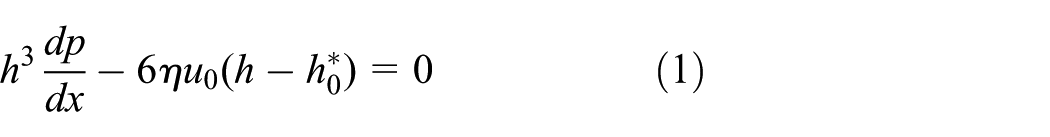
Membrane pressure
It can directly calculate

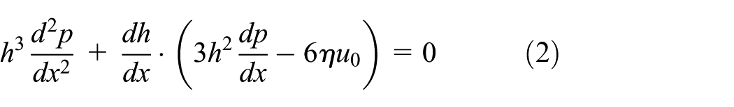
At the turning point, the membrane thickness gradient is different from zero, and then the square brackets’ expression is zero.
The membrane thickness

where
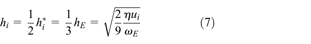
When piston rod is on outside trip, equation (4) is substituted into equation (1), and then the membrane height of the maximum pressure membrane
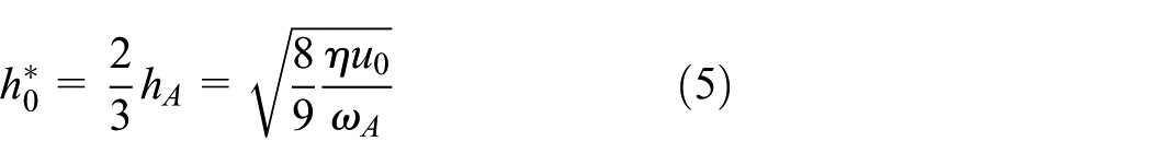
At the maximum pressure point
Due to
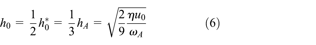
In the same way, the maximum traceable membrane thickness when the piston rod is on inside trip is obtained. In this case,
where
The net leakage of each loop with the trip length H is expressed as follows

Equation (8) shows that the net leakage is directly proportional to the piston rod diameter d and the trip length H and is equal to zero when the item in the bracket is zero or negative. In order to maintain a low leakage, sealing should generate a contact pressure distribution, which has a steep slope
Bud-shaped composite sealing material characteristics
Before the finite element analysis, material experimental tests should be carried out. Uniaxial tensile and uniaxial compression experiments have been accomplished to acquire the Mooney–Rivlin (abbreviated as M-R) model parameters of polyurethane and NBR.15–18
Uniaxial tensile experiments’ model
The experimental temperature is 23°C ± 2°C, and the relative humidity is 50% ± 10%. The specimens and dimensions are shown in Figures 4 and 5.

Material specimens of uniaxial tensile experiments: (a) NBR and (b) polyurethane.

The specimens’ dimensions.
The stress and strain data in the experiments are continuously recorded by the universal material testing machine. Finally, the uniaxial tensile stress–strain fitting curves by MATLAB, as shown in Figures 6 and 7, are obtained.

Uniaxial tensile stress–strain fitting curves for NBR.

Uniaxial tensile stress–strain fitting curves for polyurethane.
Uniaxial compression experiments
The environmental condition of the experiment is the same as the uniaxial compression. The specimens are cylinders with a diameter of 29 ± 0.5 mm and a height of 12.5 ± 0.5 mm, as shown in Figure 8.

Material specimens of uniaxial compression experiments: (a) NBR and (b) polyurethane.
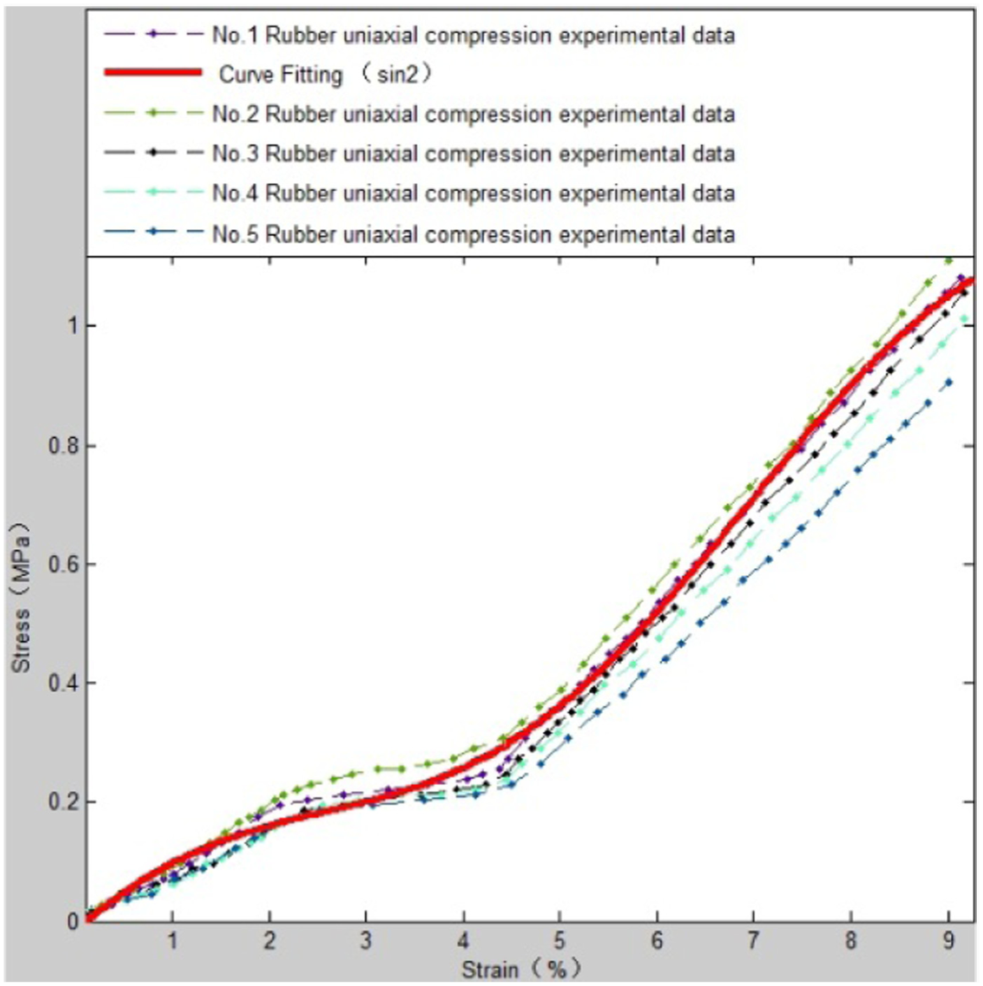
The stress and strain data are recorded in a row in the experiments by the universal material testing machine. Uniaxial compression stress–strain fitting curves have been obtained. The stress and strain data are continuously recorded in the experiment. Finally, the uniaxial compression stress–strain fitting curves by MATLAB, as shown in Figures 9 and 10, are obtained.
Uniaxial compression stress–strain fitting curves for NBR.

Uniaxial compression stress–strain fitting curves for polyurethane.
Determination of M-R constants
The data of uniaxial tension and compression fitting curves for NBR and polyurethane are entered in different-order M-R constants for calculation by MATLAB. 15 Finally, the calculation results are shown in Tables 1–4.
M-R constants of two orders (Pa).
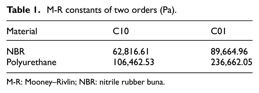
M-R: Mooney–Rivlin; NBR: nitrile rubber buna.
M-R constants of three orders (Pa).

M-R: Mooney–Rivlin; NBR: nitrile rubber buna.
M-R constants of five orders (Pa).

M-R: Mooney–Rivlin; NBR: nitrile rubber buna.
M-R constants of nine orders (Pa).
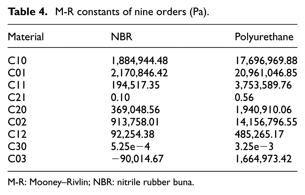
M-R: Mooney–Rivlin; NBR: nitrile rubber buna.
Finite element analysis for bud-shaped composite sealing ring
Modeling
The boundary condition of rubber sealing structure in Figure 1 is complex. The model in Figure 1 is simplified as a two-dimensional graphic, as shown in Figure 11, in order to facilitate the finite element calculation and analysis.19,20 Material parameters of sealing ring are from M-R constants of nine orders.21,22

Simplified model of bud-shaped composite sealing ring.
Stress–strain analysis under 20 MPa with radial 10% compression
The stress–strain distribution of sealing ring under different loadings is shown in Figure 12. Pressure is applied on the sealing interface in normal direction. Compression of 10% is achieved by the pressure control between the piston and cylinder head.

Stress–strain distribution under 20 MPa.
In Figure 12, the maximum contact pressure of sealing ring and the inner and outer rings with radial 10% compression is greater than the applied loadings. Therefore, this case meets the sealing requirements.
Finite element analysis of contact pressure under 20 MPa loading with radial 10% compression
Finite element analysis of contact pressure distribution curve for sealing structure is beneficial to the optimization design of the sealing structure. The contact pressure distribution curve and the corresponding values are shown in Figure 13.

Contact pressure distribution of contact line segment of bud-shaped composite sealing ring.
Contact pressure distribution can be obtained through data extraction. Different line segments of the sealing ring are integrated, as shown in Figure 14. The horizontal axis is the length of the seal ring in the horizontal direction.
Contact pressure distribution.
The maximum contact pressure of the bud-shaped composite sealing ring appears on the left side, which is close to the contact fluid area, so the leakage is very small. The accuracy of equation (8) is proved. Finite element calculation indicates that the sealing ring has a good sealing performance.
Contact pressure experiment for bud-shaped composite sealing ring
Experimental apparatus design
Experiments are carried out to verify the reliability of the finite element calculation. A stepper motor is adopted to drive the lead screw to rotate, and the piston rod is connected with the nut to realize the reciprocating motion. The apparatus is designed with the piston rod hydraulic cylinder, as shown in Figure 15. The hydraulic cylinder, transmission device, power system, and other parts are assembled, as shown in Figure 16. The sealing ring is installed between the cylinder head and the piston rod. The hydraulic pump provides different pressures to the test bench. The console controls test bench to start and stop.

3D model of the piston rod hydraulic cylinder.

The structure of experimental apparatus.
Test and analysis
Bud-shaped composite sealing ring is extruded and deformed in the hydraulic cylinder, which results in preload to achieve effective sealing effect. In order to measure the contact pressure of the bud-shaped composite sealing ring, it needs to measure the extrusion pressure, which is caused by the known area that is contacted with the sealing ring. Measurement meets more difficulties because of the narrow space. So far, no effective measurement method is found in the literature.
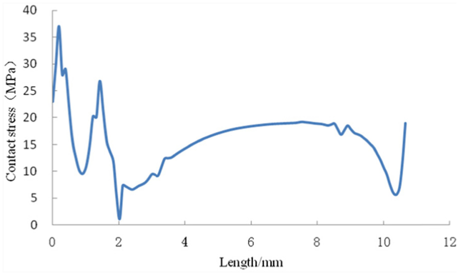
The pressure-measuring film is selected to measure the contact pressure after a series of analysis and research. The microcapsule ruptures when there is pressure, and the chromophore material and color substances react with each other. Then, the film appears red, and color density varies with different pressure levels. The pressure-sensitive film is mounted to the experimental apparatus. When the experimental apparatus works under the pressure of 20 MPa, the film with sealing ring contact pressure distribution is obtained. The film is analyzed with dedicated device and software to get the distribution curve, as shown in Figure 17. The pressure curves obtained from the experiments are compared with those of the finite element method. The maximum contact pressure points are both near the fluid area, and both have two relatively sharp pressure angles. However, the distribution and the numerical values of pressure in the horizontal direction are quite different.

Comparison between experiment and finite element analysis curves: (a) contact pressure curve of finite element analysis and (b) contact pressure curve of experiment.
Three-dimensional (3D) distribution of sealing contact pressure is shown in Figure 18, which can directly describe the contact pressure generated by the sealing ring and evaluate the sealing effect.

3D distribution of contact pressure.
Conclusion
The contact pressure distribution is very important to the sealing performance, which is analyzed by equation (8). In order to reduce the leakage, the piston seal should have actual triangle contact pressure distribution, and the biggest pressure point should be near the contact fluid area.
Through the data analysis of materials experiment, M-R model parameters of two materials are obtained. By experiments and data analysis for NBR and polyurethane, M-R model constants of two materials are obtained.
Finite element analysis of the bud-shaped composite sealing ring is carried out according to the M-R constants of nine orders. Stress–strain analysis under 20 MPa with radial 10% compression is conducted, which shows that bud-shaped composite sealing ring is suitable for dynamic seal and meets the requirements of sealing.
The distribution curves from finite element analysis, as shown in Figure 14, have verified the accuracy of equation (8) in the sealing interface fluid dynamics theory.
The seal experimental apparatus is designed and assembled to measure the contact stress of the sealing ring by the pressure-sensitive film. The contact pressure distribution curves and 3D pressure distribution fields are acquired by the experiments, which provide an experimental verification method for the reliability of the finite element analysis. In contrast to the experimental data and finite element analysis data, there are same parts and also different parts which need to be studied and analyzed further.
Footnotes
Academic Editor: Jianqiao Ye
Declaration of conflicting interests
The author(s) declared no potential conflicts of interest with respect to the research, authorship, and/or publication of this article.
Funding
The author(s) disclosed receipt of the following financial support for the research, authorship, and/or publication of this article: This work is supported by the National Basic Research Program of China (973 Program) (grant no. 2014 CB046302).