
Abstract
The seal is the key part of the cone bit. To reduce the failure probability, a new seal was designed and studied. The sealing performance and structure optimization of the X-O composite seal was analyzed and compared by finite-element analysis. The stress and contact pressure were analyzed to establish the main structural parameters that affect sealing performance and the direction of the structural optimization. By optimizing these structural parameters, including the height, and the radial and axial arc radii, an optimized structure is obtained. The results show that (1) the X-O composite seal can meet the seal requirement, the excessive height of the X seal ring is the root cause of the uneven distribution of stress, pressure, and distortion. (2) A new seal structure is obtained, the distribution of pressure and stress is reasonable and even, and the values of stress and pressure are reduced to avoid distortion and reduce the wear. Finally, the field test results of the X-O composite seal of cone bit showed that the service life of the bit bearing increased by 16% on average and the drilling efficiency increased by 11% on average compared with the original cone bit with the O seal ring.
Introduction
A cone bit is an important tool for drilling. The cone seal is the key and weakest part of the bit. Economic losses caused by the seal failure are immeasurable worldwide, and seal failures cause many accidents. Practice shows that conventional bit seals do not meet requirements well, especially when the drilling speed is high and the seal life is very short,1–6 because the working condition of the cone bit seal is very harsh, including high temperature, high abrasive medium, high load, and very small seal cavity. These working conditions and environment aggravate the failure of the seal, and also bring great difficulties and challenges to the research of the seal.7–9 Therefore, seal problems require urgent solutions.
The root causes for this behavior are (1) the large contact area of the seal ring that leads to the large friction heat and premature seal failure. (2) The stress and pressure are large and uneven, which leads to wear. (3) The large compression deformation of the rubber ring leads to excessive heat and failure. 10
The X-O composite seal structure was invented to resolve these problems. Figure 1 shows the X composite seal that is composed of an X seal ring and two O seal rings. The X seal ring is composed of four convex areas and four grooves, which can reduce the contact area and friction heat. The convex area is the main sealing surface that achieves sealing. The groove stores lubricating grease, and provides automatic compensation for compressive deformation, which has a self-sealing function. The upper and lower grooves are arranged to place the sealing ring symmetrically. The X seal ring is the main seal. The O seal ring is the auxiliary seal, which provides the seal force for the X seal ring.

Structure of X-O composite seal.
Since the O-type seal ring was invented, its structure has been improved continuously and many kinds of radial seal rings have been developed, including the rectangular sealing ring, a butterfly ring, and other different shapes of sealing rings. Structural improvements, and simulation and experimental studies have been carried out, but the causes of failure are unclear, so these seals have not performed well in applications.11–14 The double metal seal was used for the first time in a high-speed cone bit in 1987. In 2014, Xiao analyzed the distribution of the maximum Mises and shear stress on the O-ring seal under different support angles and fillet radius using the finite-element analysis software. Finally, the problem of stress concentration of the O ring was solved by optimizing the support angles and fillet radius. 15 Zhou et al. 10 studied the failure conditions of the bimetallic seal through simulation and experiment, found the root cause of the failure, optimized the seal structure, and improved the seal life. Compared with the O ring, its life expectancy has increased and it is more suitable for high-speed applications because of the high-temperature resistance of the metal ring. Because of the complex structure and multiple sealing elements of the double metal seal, the single metal seal was invented, and its structure has been optimized constantly by researchers globally. Zhang and Chen introduced the application characteristics and lubrication model of the single metal seal, and proposed an improved single metal floating seal structure (GSEMS). They analyzed and optimized the structure of the second generation of single metal floating seal SEMS25 using the finite-element software, which reduced the gap between the inner cone surface of the static ring and the rubber. The results showed that the seal SEMS25 had good sealing performance.16–18 Research has focused on structure design and finite-element simulation, but the main causes of seal failure are not understood fully. Although the life of the improved seal has been improved, its application is not ideal.19–24 We simulated and optimized the new seal based on the reason for its failure, so as to extend its life.
Basic equation of rubber material
Rubber is a type of completely super elastic material. The strain-energy density function is used to characterize the mechanical properties of rubber. The strain-energy density function is represented by

where


where
Rivlin derived the general expression of the strain-energy function mathematically. This function is termed the Mooney–Rivlin model, and is used widely

where
Equation (6) is derived from five parameters

The five-parameter equation can improve the accuracy of the simulation and the calculation efficiency. Therefore, the five-parameter equation was selected in our study.
18
The stress–strain relationship can be obtained from the compression experiments. The constants
Finite-element analysis
Finite-element model
Geometric model
Because the load and structure are symmetrical, to improve the speed and efficiency of the calculation, the model was simplified to a two-dimensional axisymmetric model.
Unit type
O- and X-type sealing rings were rubber, and a nonlinear hyperelastic material element HYPER74 was used. The bearing and cone materials were wear-resistant, and a linear incompressible material unit PLANE183 (two-dimensional eight node) was used.
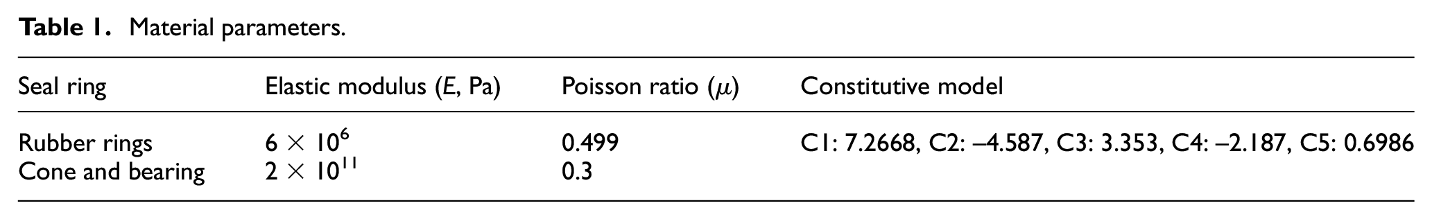
Material parameters
The characteristics of the metal material are described by the linear isotropic model with an elastic modulus E and a Poisson ratio μ. The characteristics of the rubber material are described by the models of the linear isotropic and the Mooney–Rivlin equation. The models are expressed by the elastic modulus E, Poisson’s ratio μ, and five constants. The material parameters are shown in Table 1.
Material parameters.
Grid division
Because the force analysis of the sealing rings is a focus, the mesh of the sealing ring should be close, and the mesh size was 0.2 mm. The roller and bearing were rigid, the deformation was small, the mesh was divided sparsely, and the mesh size was 0.5 mm. A square mesh was selected based on its stability and reliability.26–28
Contact pairs
The contact problem is a universal function problem with constraint conditions, and the most commonly used methods are the Lagrange multiplier, the penalty function, and direct constraint methods. A penalty-element method simulates the contact surfaces by establishing pseudo-element nodes between two possible contact surfaces. Therefore, it has been applied to an analysis of the complicated contact state, which can solve the penetration of the contact surface.
The cone and bearing are rigid, whereas the X- and O-type sealing rings are flexible. The contact between the rigid and flexible parts is a rigid–flexible contact. The contact between the two flexible parts is a flexible–flexible contact. Six contact pairs exist between (1) the upper O ring and the cone bore, (2) the upper O and X rings, (3) the lower O ring and the bearing, (4) the lower O and X rings, (5) the X ring and the cone bore, and (6) the X ring and the bearing.
Loads and boundary conditions
The calculation can be separated into the following load steps: (1) a fully displacement constraint is applied to the bearing. (2) A radical displacement is applied to the cone. (3) An axial displacement is applied to the cone. (4) A medium pressure of 1 MPa is applied to the cone. The finite-element model is shown in Figure 2.

Finite-element model.
Results and discussion
Stress
Figure 3, Tables 2 and 3 show that (1) the stresses on all contact surfaces of the X and O rings are larger than the medium pressure (1 MPa) to meet the seal requirement, which also shows that the four flanges of the X ring are the main seal surfaces (Table 1). (2) The X seal ring is twisted and deformed. As the axial size of the X seal ring is too high, it will lead to an obvious distortion. The stresses on the seal surfaces of the A and D, and B and C flanges are equal, and the stresses on the A and D flanges are larger than those of the B and C flanges (Table 1), which leads to a distorted deformation of the X seal ring, and the early damage of the A and D flanges. (3) The stress distribution of the two O seal rings is symmetrical. The stresses on the A and D, B and C, and E and F flanges are equal (Table 2). Because the structure of the upper and lower grooves of the X seal ring is the same, the deformation and stresses are the same. (4) The O seal ring is twisted and deformed. The stresses on the A and D flanges are larger than those of the B and C flanges (Table 1), which leads to a distortion of the O seal ring. (5) The stress distribution of the O ring depends on the structure of the X sealing ring (height and arc groove size). To ensure reliable sealing, a larger seal space yields a smaller deformation and stress and a longer life. (6) Through the above analysis, we know that the excessive height of the X seal ring is the root cause of the uneven force and the distortion of the X and O rings. The structure of the X seal ring is key to the seal performance. Therefore, in the study of structural optimization, the height of the X seal ring should be reduced appropriately, and the groove size of the X ring should also be improved to reduce the stress.

Von Mises stress.
Von Mises stress of X seal ring.

Von Mises stress of O seal ring.

Contact pressure
Figure 4, Tables 4 and 5 show that (1) the contact pressures on all the seal surfaces are larger than the medium pressure of 1 MPa, which can meet the seal requirements. (2) The X ring is distorted. The contact pressures on the B and C, and A and D flanges are equal and symmetrical (Table 3). Because the contact area is smaller, and the contact pressure occurs in the vertical direction of the contact surface, the contact pressures on the B2 and C1 surfaces are larger than those on the A1 and D1 surfaces, which leads to a distortion of the X seal ring (Table 3). (3) The contact pressure distribution of the two O rings is symmetrical. The maximum contact pressures on the A2 and D2 surfaces are larger than those on other surfaces of the O seal ring, which leads to a distortion of the O seal ring (Table 4). (4) The contact pressure distribution of the O ring depends on the seal surface structure of the X ring. Once the X seal ring is twisted, it will cause the O seal ring to distort. (5) Through the above analysis, we know that the uneven and large contact pressure is the main cause for the distortion of the X and O rings. Under the premise of ensuring effective sealing (contact pressure is greater than the medium pressure), the smaller contact pressure yields a more even distribution, and reduced wear yields a longer seal life. Therefore, in the study of structural optimization, the structure should be improved to reduce the contact pressure and make the pressure distribution reasonable.

Contact pressure.
Maximum contact pressure of X seal ring.

Maximum contact pressure of O seal ring.

Structure optimization
The optimization simulation process of the new structure is the same as that of the original structure. It is not described in detail, and we compare only the simulation results.
Optimization criteria
Through the above analysis, optimization criteria are obtained. To ensure effective sealing (stress and contact pressure is larger than the medium pressure of 1 MPa), the pressure and stress distributions are reasonable and even, and the values of stress and pressure are reduced to avoid distortion and reduce wear.
Effects of X sealing ring heights
Structure
From the previous analysis, it is known that the large height of the X sealing ring is the main reason for the distortion, so its height should be reduced within allowable limits. The structure dimensions are shown in Figure 5.
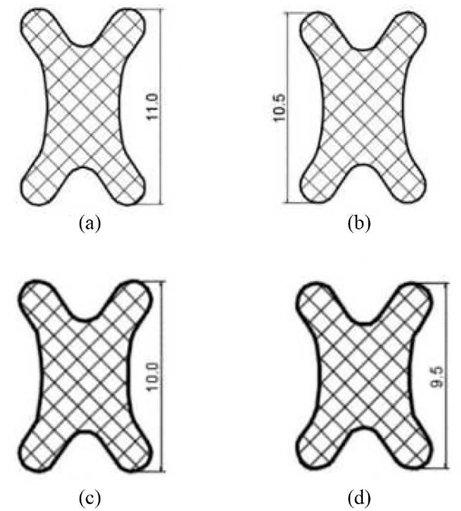
X seal ring with different heights: (a) original height 11 mm, (b) height 10.5 mm, (c) height 10 mm, and (d) height 9.5 mm.
Stress
Figure 6 shows that (1) with the decrease in height, the distortion of the X seal ring is reduced. When the height of the X seal ring is 9.5 mm, the stress distribution is the most uniform, and almost no distortion results. (2) The maximum stresses of the X seal ring with 11- (original seal), 10.5-, 10-, and 9.5-mm heights are 7.92, 4.63, 4.9, and 3.43 MPa, respectively. The maximum stress of the X sealing ring with a height of 9.5 mm is the smallest, and the wear is also the smallest.

Stress comparison of X seal ring with different heights: (a) original height 11 mm, (b) height 10.5 mm, (c) height 10 mm, and (d) height 9.5 mm.
Contact pressure
Figure 7 shows that (1) the height has changed, but the pressure distribution on the sealing surface remains unchanged, which implies that the maximum contact pressure occurs in the middle, and the minimum contact pressure occurs on both sides of the seal surface. Therefore, the height change has no effect on the pressure distribution. When the heights are 10 and 9.5 mm, the pressures of the A and D flanges are largest, which helps prevent mud from reaching the seal surface, because the mud enters the seal from the D flange (the cone side), and so the distribution is better. (2) When the height is 9.5 mm, the pressures on every seal surface of the O ring are almost the same, and the pressure distribution is the most uniform. (3) The maximum contact pressures of the X seal ring with 11- (original seal), 10.5-, 10-, and 9.5-mm heights are 3.77, 3.7, 5.1, and 3.68 MPa, respectively. When the height is 9.5 mm, the maximum pressure is the smallest, and the wear is also the smallest.

Contact pressure comparison of X seal ring with different heights: (a) original height 11 mm, (b) height 10.5 mm, (c) height 10 mm, and (d) height 9.5 mm.
Therefore, the height of 9.5 mm is the final choice in the optimization result.
Effects of radial arc radii of X sealing ring
Structure
Because the height of the sealing ring is related to the radial arc radius, we should optimize the radial arc radius. The structure dimensions are shown in Figure 8.

X seal ring with different radial arc radii: (a) original radius 10 mm, (b) radius 9 mm, and (c) radius 11 mm.
Stress
Figure 9 shows that (1) no matter how the arc is changed, the bending deformation of the X seal ring is not improved, and the stress distribution is also unchanged. The stress distribution of the optimized structure is basically the same as that of the original structure. (2) The change in stress value is very small. When the radial arc radii are 10 (original seal), 9, and 11 mm, the maximum stresses are 7.92, 7.93, and 7.87 MPa, respectively. Therefore, the change in radial arc radius has little effect on the distribution and values of the stress.

Stress comparison of X seal ring with different radial arc radii: (a) original radius 10 mm, (b) radius 9 mm, and (c) radius 11 mm.
Contact pressure
Figure 10 shows that (1) in the same way, the change in arc radius has little effect on the pressure distribution. (2) The change in stress value is very small. When the radial arc radii are 10 (original seal), 9, and 11 mm, the maximum pressures are 3.77, 3.78, and 3.83 MPa, respectively. Therefore, the change in radial arc radius has little effect on the contact pressure. We still select 10 mm as the radial arc radius.

Contact pressure comparison of X seal ring with different radial arc radii: (a) original radius 10 mm, (b) radius 9 mm, and (c) radius 11 mm.
The above analysis indicates that the radial arc radius does not play a significant role in improving the sealing performance.
Effects of axial arc radii of X sealing ring
Structure
The change in axial arc radii is shown in Figure 11.
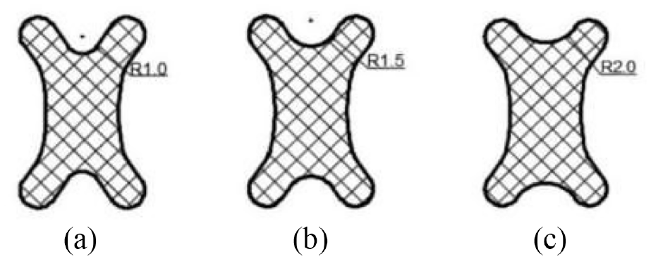
X seal ring with different axial arc radii: (a) original radius 1 mm, (b) radius 1.5 mm, and (c) radius 2 mm.
Stress
Figure 12 shows that (1) the stress distribution and distortion are unchanged. (2) The change in stress values is obvious. When the axial arc radii are 1 (original seal), 1.5, and 2 mm, the maximum stresses are 7.92, 8.1, and 10.4 MPa, respectively. When the radius is 1 mm, the maximum stress is the smallest, and the deformation is also the smallest.

Stress comparison of X seal ring with different axial arc radii: (a) original radius 1 mm, (b) radius 1.5 mm, and (c) radius 2 mm.
Contact pressure
Figure 13 shows that (1) the pressure distribution is similar before and after the structure optimization. With an increase in radius, the rubber rings contact the circles of the X sealing ring, and the seal pressure occurs over the entire groove. (2) The change in sealing pressure is not obvious. When the axial arc radii are 1 (original seal), 1.5, and 2 mm, the maximum pressures are 3.77, 3.91, and 4 MPa, respectively.

Contact pressure comparison of X seal ring with different axial arc radii: (a) original radius 1 mm, (b) radius 1.5 mm, and (c) radius 2 mm.
Through the above analysis, we know that the axial arc radius has little effect on the distribution of stress and contact pressure, but a large effect on the stress value. Therefore, we still choose the original arc radius as 1 mm because of the minimum stress and pressure.
Structure comparison before and after optimization
Structure
The seal structures before and after optimization are shown in Figure 14.
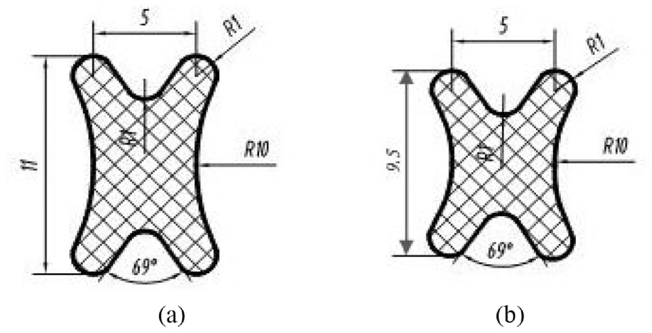
Structure of (a) old and (b) new X seal rings.
Stress
Figure 15 shows that the stress distribution of the new seal is more even, and that the stresses on the four flanges are almost equal. The maximum stress (3.44 MPa) of the new seal is much smaller than that (7.92 MPa) of the old seal, which is bigger than the medium pressure required to meet the seal requirement.

Stress comparison of (a) old seal and (b) new seal.
Contact pressure
Figure 16 shows that in the axial direction, the pressure of the flange near the cone side of the new seal is larger, which can prevent the mud from entering the seal. The pressure value of the new seal is reduced, and the maximum contact pressure (3.68 MPa) of the new seal is smaller than that of the old seal (3.77 MPa), which is also larger than the medium pressure to meet the seal requirement.
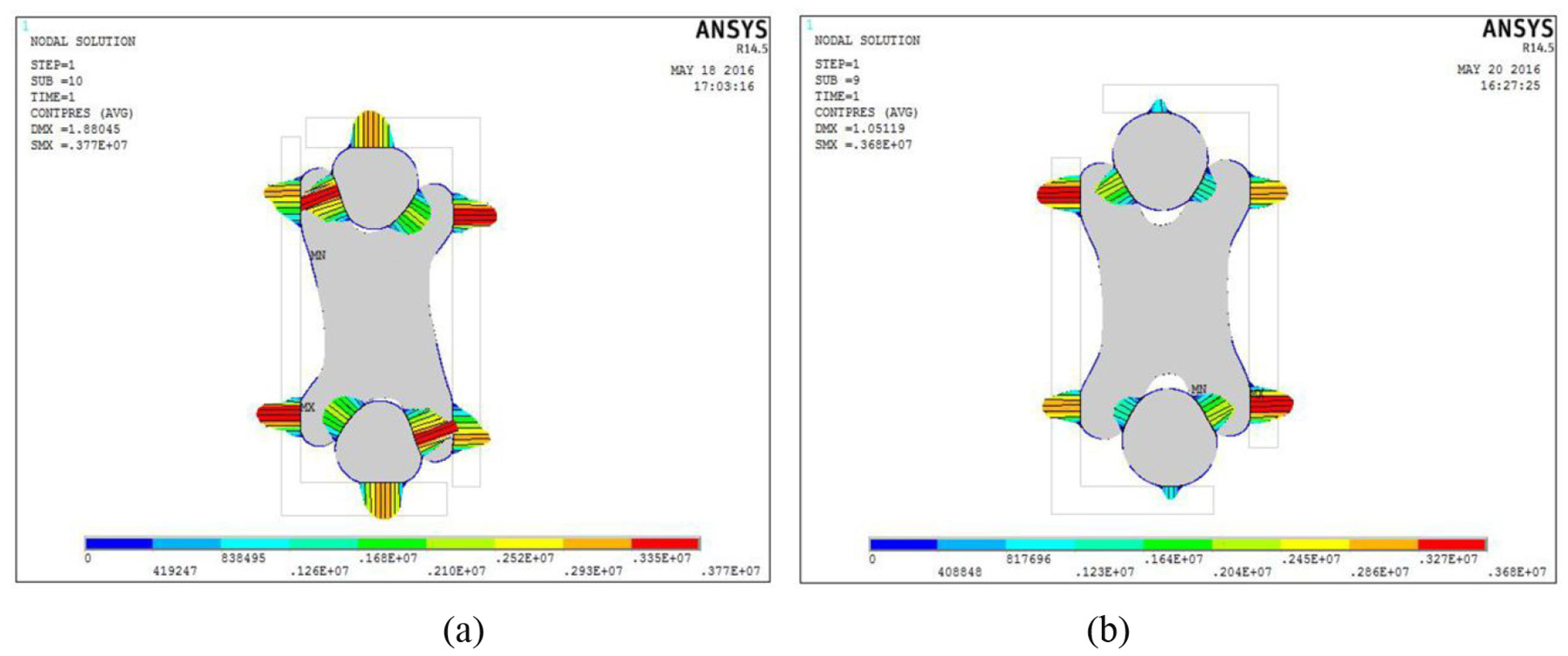
Contact pressure comparison of (a) old seal and (b) new seal.
Conclusion
The X-O composite seal can meet the seal requirement. The excessive height of the X seal ring is the root cause of the uneven distribution in stress, pressure, and distortion. The structure of the X seal ring is the key to the sealing performance.
To ensure effective sealing, through an optimization of the height and radial and axial arc radii of the X seal ring, the distribution of pressure and stress of the new seal is reasonable and even, and the values of stress and pressure are reduced to avoid distortion and to reduce wear.
Testing and application
In December 2016, two new X-O composite seals were manufactured and mounted in two cone bits. These two cone bits were numbered as 81/2XHP007 and 81/2XHP009. The two cone bits were tested at the oil field. Field test results showed that the service life of the bit bearing increased by 16% on average and the drilling efficiency increased by 11% on average compared with the original cone bit with the O seal ring.
Footnotes
Appendix 1
Handling Editor: James Baldwin
Declaration of conflicting interests
The author(s) declared no potential conflicts of interest with respect to the research, authorship, and/or publication of this article.
Funding
The author(s) disclosed receipt of the following financial support for the research, authorship, and/or publication of this article: This article is supported by Open Fund (OGE201403-18) of Key Laboratory of Oil & Gas Equipment, Ministry of Education (Southwest Petroleum University).