
Abstract
Distributed computing strategy over a network of wireless sensors has emerged as a promising application in order to enable real-time structural health monitoring. Most previous studies of distributed computing strategy consider relatively simple operations like modal parameters identification (e.g. frequencies and modal shapes) that cannot directly assess structural health condition demanded by many practical engineering applications. This article focuses on developing distributed computing strategy techniques in wireless sensor networks used for direct stiffness estimation of structural damage locations and extent. An improved frequency-domain regression method is proposed to detect and quantify damage in frame structures. In the proposed method, the static condensation technique is adopted to reconstruct the rotational responses on joints, which is considered as inputs to estimate stiffness. Therefore, this improved method provides a more practical and accurate tool for structural damage detection. A numerical simulation of a five-story two-bay frame structure demonstrates that the proposed damage detection method using a limited number of wireless sensors can identify, locate, and quantify the structural stiffness changes accurately.
Keywords
Introduction
Over the past decades, structural health monitoring (SHM) has become an important field in civil engineering, with the goal of continuous and periodic assessment of the safety and integrity of the civil infrastructures.1–6 Smart wireless sensors rapidly arise as a new technology in SHM by significantly overcoming many of the inherent difficulties and limitations associated with traditional wired sensors, such as laying cables, installation, and maintenance. A smart wireless sensor is often battery powered and equipped with an independent on-board microprocessor that can be used for digital signal processing. Recent studies have demonstrated the potential of applying wireless sensor networks (WSNs) to monitor large-scale structures using a dense array of sensors.7–11 However, due to limited energy in WSN, the efficient use of WSNs in SHM is still a challenge task. 12
Data communication in WSNs is a major concern for energy consumption. A single sensor node which generates 16-bit vibration data along three axes at 500 samples per second can easily consume one fourth of the nominal data rate of the IEEE 802.15.4 low power radio. 13 A large structure typically comprises hundreds of members and will require at least two tri-axial sensors measuring accelerations at each end of every member, so that the damaged members can be detected. Clearly, transferring raw sensor data in a continuous mode for a traditional central data repository is not an efficient way for the WSNs. Therefore, distributed computing strategy (DCS) has been introduced to process the raw data within the network before transmitting it to a central computer. 14
With developments in sensing and computing technologies, modal information extraction is no longer the most challenging part of the DCS implementation for SHM. The peak picking (PP) method and the frequency-domain decomposition (FDD) technique are successfully modified for use within a distributed (i.e. decentralized) WSN.15,16 However, the estimated modal properties do not directly yield light on possible damage location and extent, implementing proper data analysis methods to explicitly and efficiently detect damage is still an important work. Seeking an efficient distributed damage identification method is an inevitable trend in the field of wireless monitoring system.
Several damage detection methods have been developed in recent years for DCS in WSN applications,17–19 but most of them are resulted from system identification methods which can be computationally expensive, generally through various of matrix computations such as eigen decomposition, 20 singular value decomposition (SVD), 21 to implement for large systems with a high number of sensing locations. Thus, more efficient damage detection methods for DCS are needed.
Structural damage affects the dynamic properties of a structure, resulting in a change in the statistical characteristics of the measured acceleration time histories. Thus, damage detection can be performed using time series analysis of vibration signals measured from a structure before and after damage. This kind of approach has gained a lot of attention due to its potential for automated analysis, and lots of efforts have been made to enable the approach to detect and localize the damage.22–24 The basic process for this kind of approach is to fit the dynamic response of healthy and damaged structures to the time series models and extract the damage features for detecting the damage. Nevertheless, most of the damage features obtained from modal data are easily influenced by environmental and measurement noise. Therefore, these damage features are difficult to apply to practical SHM.
The frequency-domain regression method (FDRM) was developed by Yao and Pakzad 25 to calculate the regression coefficients and assess damage in shear frame structures. The regression coefficients provide a direct estimate of the local stiffness and can be readily used as damage features. For the calculation of the regression coefficients, spectral estimating technique has been elaborated in Yao and Pakzad. 25 This technique provides a way to use local acceleration responses of a frame structure to estimate its local stiffness. In Yao’s work, the FDRM was proven more effective than the time-domain regression method (TDRM) in damage detection of a shear frame structure, by eliminating the displacement reconstruction step and all the associated computational cost and estimation errors. Yet, when joint rotations exist, the performance of FDRM degrades. In fact, the nodal rotations cannot be omitted from many real applications. Nevertheless, measurements on rotational effects are very difficult to be obtained properly within the scope of WSN-based SHM. This is viewed as a drawback in using this technique for practical applications.
In this study, an improved FDRM method is proposed where the rotational responses are directly calculated from the measured translational displacement using the static condensation technique. An obvious advantage of this method is that it eliminates the acquiring of rotation degrees of freedom (DOFs) and all the associated computational cost, therefore extending the FDRM more generally applicable to regular frame structures. This improved FDRM also provides a practical and easy to-be-interpreted tool for DCS algorithm in hierarchical WSNs. Simulation results demonstrate that the improved method employed in a limited number of wireless sensors can identify, locate, and quantify the structural stiffness changes accurately even in the case of high-level noise in the measured data.
This article is organized as follows. Section “Brief description of the FDRM” gives the relevant background of the FDRM for stiffness estimation in shear frames. Section “Improved regression model–based damage detection method” presents the improved FDRM approach using reconstructed rotational response, and then, a numerical validation for the rotation reconstruction technique is performed. In section “WSN-based DCS,” a WSN-based DCS is briefly presented. In section “Numerical simulation study,” a numerical simulation of a five-story two-bay frame structure is performed to investigate the feasibility of the proposed approach in WSN. Finally, concluding remarks are summarized in section “Conclusion.”
Brief description of the FDRM
The FDRM is a relatively new method to assess damage in frame structures and estimate the stiffness along the structure from regression constants. It is assumed that localized damage is directly related to a local reduction of stiffness in the structure.
The equations of motion of shear frame structure shown in Figure 1 under external force

where


Multilayer shear frame structure.
According to the Yule–Walker equation, multiply both sides of equation (2) with

Taking expectation of both sides of equation (3) and assuming that input excitation at node

where R(·) are the correlation functions of the acceleration responses. Taking the one-sided Laplace transform of equation (4)
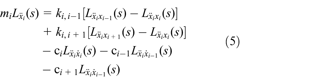
where L(·) represents the Laplace transform (


Real component of acceleration cross spectrum density function

Real component of acceleration auto-power spectrum density function

Imaginary component of acceleration cross spectrum density function
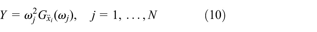
N—sampling points
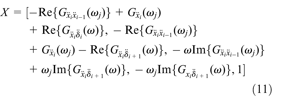
where
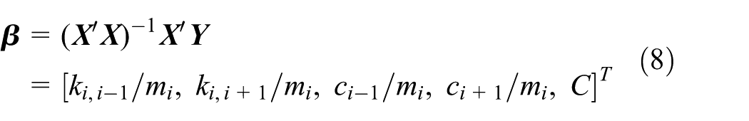
In equation (8), the stiffness and damping coefficients can be estimated from
Improved regression model–based damage detection method
In the original FDRM, the procedure for determining the regression constants in regular frame structures uses the rotational information directly, thus requiring measurement of all joint rotational responses in the frame. This is a very demanding requirement; in practice, only floor translational accelerations are usually measured. Therefore, the original FDRM for applications in structural damage detection is still an issue. In this section, an improved FDRM is proposed to estimate the average rotational responses from the floor translational responses using rotation reconstruction method, so that the regression-based detection method can be performed without measuring joint rotations.
Improved FDRM algorithm
An improvement of FDRM is proposed in this section. The model reduction technique
26
is used to convert a general n-story m-bay plane frame structure into beam-like model. Through model reduction, the original frame structure (Figure 1) is simplified to a beam model shown in Figure 2. For non-end floor in this model, each node has one horizontal translation xi and two rotations

Beam-like structure model.
Then, the general motion equation for ith floor can be expressed as follows
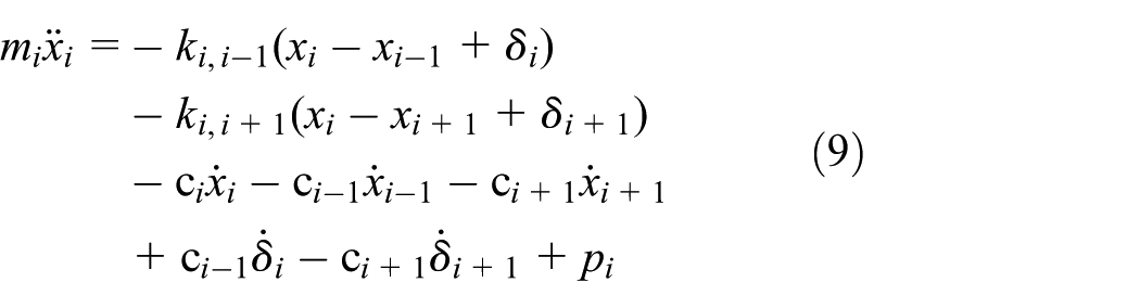
where δi is the average floor rotations

Therefore, in the improved FDRM, it is possible to estimate the effects of nodal rotation on stiffness when flexible beams are present in frame structures.
The rotation response reconstruction method
In the improved FDRM above, joint rotation responses are needed as input to identify the stiffness of the frame structure which is very difficult to be obtained in applications. Usually, only floor translational accelerations are measured in SHM and damage detection. Here, the static condensation technique is used to estimate the average rotational responses from the floor translational responses, so that the improved FDRM can be performed without measuring joint rotations. As discussed in the above section, the regular frame structure can be simplified to a beam-like structure. A beam element model is depicted in Figure 3, and its rotational responses will be reconstructed from translational responses using the static condensation technique proposed by Guyan. 27 This method divides DOFs into retained freedoms and condensate freedom through compensating the mass and stiffness matrix using the potential energy conservation principle.
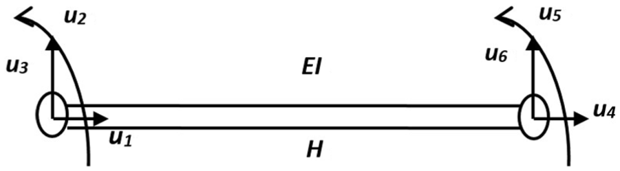
Substructure of beam-like model.
Neglecting the axial beam displacement u1 and u4, the element stiffness matrix of the beam is

where Hi means the length of ith beam. Combining the element stiffness matrices of (i-1)th, ith, and (i+1)th floors, the global stiffness matrix for a standard substructure can be derived as

Hence, the following dynamic equation of free vibration of the substructure neglecting structural damping can be obtained

where subscripts t and r are for horizontal displacement and rotation, respectively. Here,

In equation (16), rotation responses can be represented by translation displacements as

where


The average floor rotational acceleration is defined as
Verification of the static condensation technique
To verify the effectiveness of the static condensation technique, a simply-supported aluminum beam model is simulated in this section. Figure 4 shows the finite element (FE) model of the simply-supported beam (span = 4 m) with 10 beam elements (11 nodes, data measuring points). The beam has a rectangular section with a dimension of 0.3 × 0.2 m2, modulus of elasticity E = 2.4×10¹⁰ MPa, density ρ = 2500 kg/m3, and Poisson’s ratio = 0.3. In this model, it is assumed that the nodes coincide with the locations of measurement sensors. To perform the rotation reconstruction, white gauss noise with 0.1 power spectral density is applied on node 5 in vertical direction as the external force. Structural responses of 10 s with a sampling rate of 1000 Hz are generated.

Simply-supported beam model (unit: mm).
The rotational responses of each node are extracted from the FE model using the general purpose FE software ANSYS as the accurate rotations θ of the beam. Meanwhile, the displacements of each node in vertical direction are also collected as the input of the static condensation technique. The reconstructed rotation responses
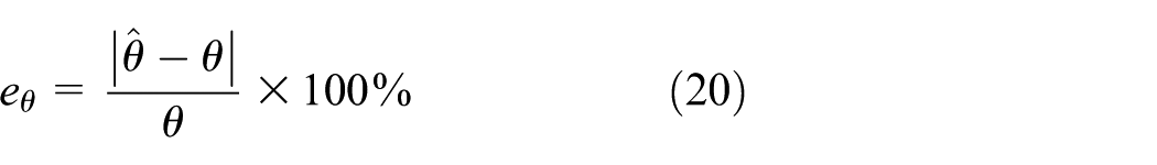
Figure 5 shows the relative error of the reconstructed rotation up to 30% noise level. As shown in Figure 5(a), all of the relative errors are under 0.1% when noise is present. While in Figure 5(c), even when the noise increases to 30%, the relative error is still under 5%. It demonstrates that the static condensation technique achieves rotation reconstruction accuracy from acceleration measurements and has excellent anti-noise property.

Relative error of the reconstructed rotation in different noise level: (a) without noise, (b) with 10% noise, and (c) with 30% noise.
WSN-based DCS
Hierarchical organization
The conceptual hierarchical organization of the DCS approach 23 is shown in Figure 6. The measured information on a single wireless node is processed and transferred locally within a community (substructure) to the cluster head, in such a way that only limited information is sent back to the central station to provide the condition of the whole structure. Leaf sensors are grouped together to form different substructures, namely, different wireless sensor clusters. Cluster heads collect measured responses from its own and leaf nodes, and process the local damage detection in substructures. In DCS approach, sensors may participate in multiple clusters. Hence, adjacent cluster heads may need to interact with others to exchange information.28,29

Sketch of hierarchical organization.
For adjacent sensor communities, cluster heads share the same information except the bottom and top floors. Therefore, comparing the identified stiffness value of the adjacent substructures can further reduce the damage misjudgment. If the identification results are the same, then the cluster head transfers them directly to the base station, whereas if the results are different, the cluster head will return to the previous steps (in each substructure).
Implementation strategy
The improved FDRM damage detection procedure which is used to calculate stiffness directly for regular frame structures is illustrated in Figure 7. In this procedure, identification of all floor stiffness is completed based on substructures. In this line, different substructures represent different wireless sensor clusters. For instance, a non-end substructure includes three floors, and the sensor on middle floor is considered as the cluster head and others on adjacent floors as leaf nodes. The leaf nodes measure acceleration signals of the substructure and send them back to the cluster heads. In the cluster heads, the regression-based damage detection algorithms are performed to identify the floor stiffness of the substructure. After calculation, the cluster heads transfer the detected stiffness to the base station. Compared to traditional centralized algorithms which require all the measured information to be transferred to base station, the DCS algorithm can reduce 1/3 data communication demands in WSN.
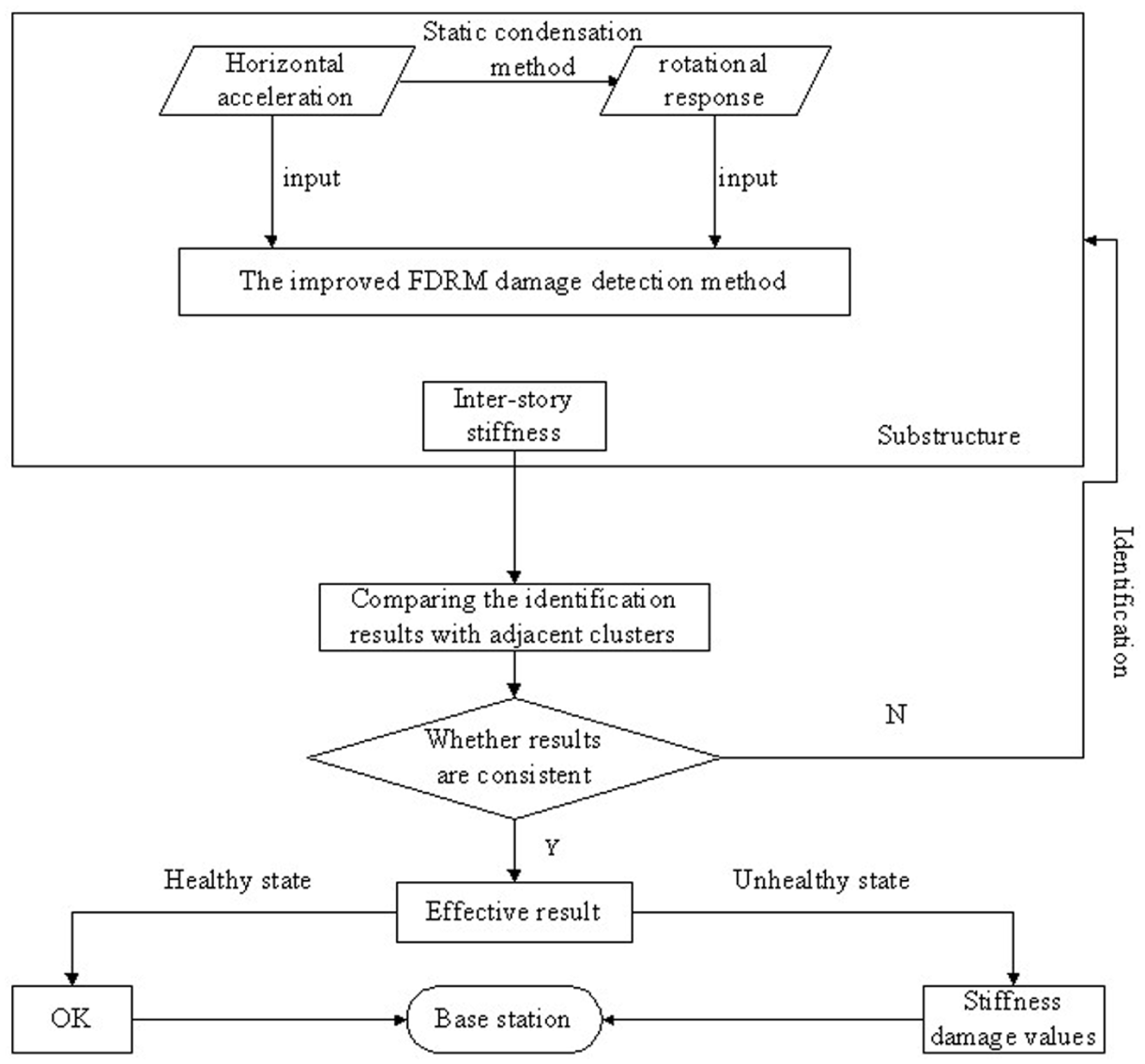
Process of the improved FDRM in WSN.
Numerical simulation study
Model description
In order to verify the validity of the improved FDRM, a numerical simulation of five-story two-bay frame structure is introduced. As shown in Figure 8, the parameters of the frame structure are as follows: height of each floor Hi = 3 m (i = 1,…, 5); span of each bay Lj = 4 m (j = 1, 2); the flexural rigidities of all beams and columns are 15 × 104 KN m2; the linear mass of all beams and columns is 200 kg/m; the weight of each floor is mi = 105 kg; and the equivalent stiffness between the floors

Five-story two-bay frame structure model.
Damage patterns
In addition to the undamaged structure, three damage patterns are studied as follows:
Damage pattern 1 (DP1): reduction in the stiffness of the middle column on the first floor to 30% of its original value k1 = 2.25 × 10⁵ KN/m;
Damage pattern 2 (DP2): reduction in the stiffness of both the middle columns on the first and third floors to 30% of its original value k1 = k3 = 225 MN/m;
Damage pattern 3 (DP3): mass of the fourth floor is increased with 0.2 × 10⁵ kg in the center of the floor.
In this study, the damage feature (DF) is taken as the ratio of stiffness k of the damaged and undamaged structures and the magnitude of this ratio represents the severity of the anomaly. This form of the damage feature is shown in equation (21)

Result of substructure identification
Random excitation is applied at each floor level of the frame. To verify that the improved FDRM work well with noise, the acceleration response of each floor is collected from the model, and 10% and 30% random white noises are added artificially for each pattern. Five different wireless sensor clusters are created for each substructure as shown in Table 1. The inputs and outputs of the auto regressive (AR) models for each sensor cluster are also shown in Table 1.
Inputs and outputs of the improved FDRM.

DP 1
For this case, the stiffness of all the columns on the first floor is reduced to 70% of its original value. The stiffness identification using the improved FDRM is explained in the previous sections. The values of identified stiffness calculated from the acceleration data and the damage features in different noise levels are presented in Figures 9–11.

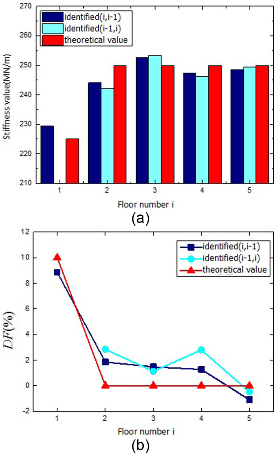
Identified results of improved FDRM for the DP1 without noise: (a) identified floor stiffness and (b) damage features (%).

Identified results of improved FDRM for the DP1 with 10% noise: (a) identified floor stiffness and (b) damage features (%).
Identified results of improved FDRM for the DP1 with 30% noise: (a) identified floor stiffness and (b) damage features (%).
As shown in Figures 9–11, the dark blue pillars stand for the equal story stiffness identification value of a particular floor in its substructure. The blue pillars stand for the equal story stiffness identification value of the same floor in its adjacent substructure. The red pillars stand for the accurate stiffness value of the corresponding floor. It is observed that the identified stiffness coming from the first floor is considerably lower than those of other floors, meaning that the damage has occurred in the first floor. Another observation is that the damage features of the identified value for the first floor are very close to the real value (for the whole floor, stiffness reduction is 10%), while other identified damage features are slightly around 0 even under 30% noise added. Hence, it can be concluded that the methodology is successful at detecting and locating the damage in the frame for this case. Meanwhile, the improved FDRM is shown to be relatively robust to noises. It should be noted that the first floor is an exterior floor in the frame and there is only k10 exists for this floor.
DP 2
The damage pattern 2 consists of the damage in pattern 1 in addition to reduction in the stiffness of the middle column on third floor to 30% of its original value. Figures 12–14 show the identified results using the proposed methodology with different noise level.
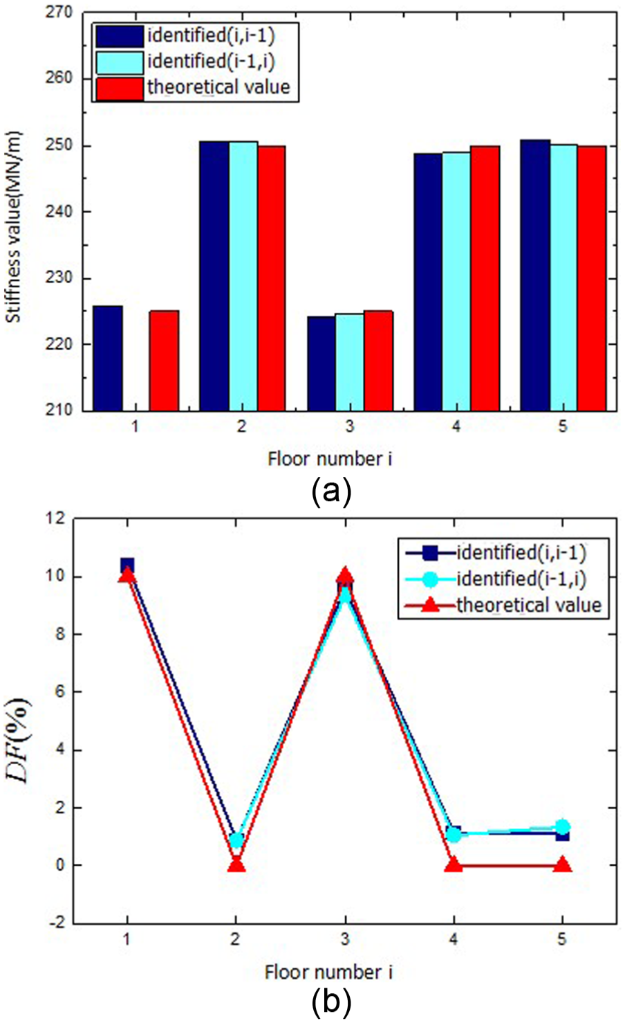
Identified results of improved FDRM for the DP2 without noise: (a) identified floor stiffness and (b) damage features (%).

Identified results of improved FDRM for the DP2 with 10% noise: (a) identified floor stiffness and (b) damage features (%).

Identified results of improved FDRM for the DP2 with 30% noise: (a) identified floor stiffness and (b) damage features (%).
In these figures, it can be seen that the 10% stiffness reduction is accurately identified and localized by the damage features on the first and third floors when the acceleration data used are noise free. When measurement noise is added to the data, the accuracy of the DF results is slightly affected for the interior floors but relatively obvious for the exterior floor (i.e. the fifth floor), because the noise content of the vibration measurements actually becomes amplified through the rotation reconstruction process. Nevertheless, the improved FDRM is still generally effective in multi-damage detection.
DP 3
From the previous damage patterns, we know the change of stiffness can be detected, localized, and quantified by the improved FDRM using acceleration responses only. In addition to the stiffness reduction cases, a mass of 0.2 × 10⁵ kg is added on the fourth floor to test whether the proposed method can distinguish the damage between the change of mass and stiffness.
As shown in Figure 15, the additional mass on the fourth floor causes stiffness reduction in the first, second, third, and fourth stories consistently, while the stiffness of the fifth floor remains unchanged (DF5 = 0). This stiffness reduction can be derived from the load–displacement effects, which can be considered as a main difference between the damage features for the change of mass and stiffness.

Identified results of improved FDRM for the DP3 without noise: (a) identified floor stiffness and (b) damage features (%).
Conclusion
In this study, an improved FDRM is formulated and utilized as a practical version of the DCS for damage detection and quantification in WSN-based SHM. This method relies on acceleration measurements only to detect stiffness loss for regular frame structures with joint rotations. A simulated beam model is analyzed to verify the rotation reconstruction technique. The performance of this technique is shown to be effective for the rotation reconstruction application.
For application of the proposed damage detection method in hierarchical WSNs, adjacent wireless sensors are grouped together to form clusters according to substructures. Raw acceleration signals are processed on cluster head before they are sent back to the base station, therefore only identification results need to be transferred within the WSN and thus save energy. A numerical example of a five-story two-bay plane frame structure demonstrates that by combining the improved FDRM and DCS, the WSN is able to accurately identify, localize, and quantify structural damages even with large measurement noise. Furthermore, it is also observed that the stiffness estimate from substructure identification is favorable since it has less power costs due to clustering and data transmission. This feature is very important for detecting damage locations and severity in WSN-based SHM. Future work includes embedding the damage detection method in wireless sensors for real-time monitoring of structures and continuous research of the proposed DCS algorithm.
Footnotes
Academic Editor: Jun Li
Declaration of conflicting interests
The author(s) declared no potential conflicts of interest with respect to the research, authorship, and/or publication of this article.
Funding
The author(s) disclosed receipt of the following financial support for the research, authorship, and/or publication of this article: This work was financially supported by the National Key Technology R&D Program of China (no. 2014BAL05B06), National Science Foundation of China (no. 51278156), Guangdong International Co-op Project (no. 2014A050503016), Shenzhen Science and Technology Projects (nos JCYJ20160525163140206 and GJHZ20150312114346635), and the authors are grateful to the authorities for their support.