
Abstract
Sensor barrier coverage has been recognized as an appropriate coverage model for intrusion detection, and many achievements have been obtained in two-dimensional terrestrial wireless sensor networks. However, the achievements based on two-dimensional assumption cannot be directly applied in three-dimensional application scenarios, for example, underwater wireless sensor networks. In this article, we aim to devise a fully distributed deployment algorithm for constructing maximum-level underwater strong k-barrier coverage with available mobile sensors in underwater environment to satisfy the requirement of underwater security-related applications. We first analyze how to form underwater strong one-barrier coverage with minimum mobile sensors, based on which we obtain the minimum number of sensors required for constructing underwater strong one-barrier coverage and the corresponding optimal final positions of these sensors. Then, we propose a fully distributed deployment algorithm for constructing maximum-level underwater strong k-barrier coverage with available mobile sensors in three-dimensional underwater environment. We show that the proposed algorithm has a guaranteed termination after a finite time and is able to self-heal the underwater strong k-barrier coverage to deal with sudden sensor failures. Experimental results validate our analysis and show that the proposed algorithm outperforms both Hungarian and HungarianK in terms of duration and achieves performance close to them with respect to several performance metrics.
Keywords
Introduction
Wireless sensor networks (WSNs) have many real-life applications such as environmental monitoring, battlefield surveillance, and intrusion detection. As an important problem in WSNs, barrier coverage is garnering more and more attention in recent years.1–5 Compared with the area coverage problem, barrier coverage does not necessarily cover every point of the monitored region, but rather only needs to detect intruders that cross the border. 4 Therefore, it is more cost-efficient for large-scale deployment of wireless sensors and has been widely employed in practical security-related applications, for example, international border surveillance, intrusion detection, and critical infrastructure protection.
Most existing works on barrier coverage assume that sensors are deployed in two-dimensional (2D) long thin belt region, where a barrier is a chain of sensors from one end of the deployment region to the other end with overlapping sensing zones of adjacent sensors. This assumption is reasonable in 2D terrestrial WSNs where the height of the network is usually negligible as compared with its length and width. However, the 2D assumption may not be appropriate when considering WSNs in three-dimensional (3D) application scenarios, for example, underwater wireless sensor networks (UWSNs), where the sensors are finally distributed over 3D underwater environment. As technology advances, efforts are currently underway to extend the applications of WSNs from 2D to 3D application scenarios, and many achievements have been obtained in 3D UWSNs.6–9 In terms of sensor barrier coverage, an underwater sensor barrier has been considered for detecting submarine intrusion in marine environment. 10
Compared with terrestrial WSNs, UWSNs have many differences in terms of topology, communication media, deployment, bandwidth, and so on. For example, the topology of terrestrial WSNs is generally static or low dynamic, while that of UWSNs is highly dynamic due to continual movement of nodes caused by water current. Sensor nodes in terrestrial WSNs communicate with each other by radio wave which is high frequency, while in UWSNs, sensor nodes generally communicate with each other by acoustic wave which is low frequency. Furthermore, different from the terrestrial WSNs where sensors are distributed in a 2D plane, in UWSNs (in this article, we only consider sensor barrier coverage in UWSNs where the sensors are deployed in 3D underwater environment), the sensors are distributed at different depths in 3D underwater environment. In this case, a sensor barrier is not a chain of sensors from one end of the deployment region to the other end with overlapping sensing zones of adjacent sensors any more. Instead, a sensor barrier deployed in underwater environment should be a set of sensors with overlapping sensing zones of adjacent sensors that covers an entire (curly) surface that cuts across the 3D underwater space. 11
In this article, we aim to devise a fully distributed deployment algorithm (FDDA) for constructing maximum-level underwater strong k-barrier coverage with available mobile sensors in underwater environment, to satisfy the requirement of underwater security-related applications. The notion of k-barrier coverage is first defined by Kumar et al., 12 they introduced two types of k-barrier coverage including weak barrier coverage, which guarantees to detect intruders moving along congruent paths, and strong barrier coverage, which guarantees to detect intruders no matter what crossing paths they choose. Generally, a strong k-barrier coverage is constituted with k strong one-barrier coverage. In practical underwater environment, as the existence of sudden sensor failures and water current, which may lead a sensor to deviate from its desired position, a strong one-barrier coverage usually fails to provide adequate service quality. Hence, many real-life underwater applications require strong k-barrier coverage to guarantee their service quality.
The main contributions of this article can be outlined as follows:
We analyze how to form underwater strong one-barrier coverage with minimum mobile sensors, based on which we obtain the minimum number of sensors required for constructing underwater strong one-barrier coverage and derive the corresponding optimal final positions of these sensors.
Considering the fact that a strong k-barrier coverage consists of k strong one-barrier coverage, we propose a FDDA for constructing maximum-level underwater strong k-barrier coverage with available mobile sensors in underwater environment. The proposed algorithm can drive all mobile sensors distributed in underwater space automatically moving to desired positions and finally provide maximum-level underwater strong k-barrier coverage.
We evaluate the performance of the proposed algorithm by extensive experiments. Experimental results show that the proposed algorithm has a guaranteed termination after a finite time and is able to self-heal the underwater strong k-barrier coverage to deal with sudden sensor failures. Furthermore, the proposed algorithm outperforms both Hungarian and HungarianK in terms of duration and achieves performance close to them with respect to several performance metrics.
The rest of the article is organized as follows. Next section reviews the related work. In section “Network model and problem statement,” we explain the network model and provide the problem statement. Next, in section “Underwater strong one-barrier coverage,” we analyze how to form underwater strong one-barrier coverage with minimum sensors in underwater environment, and obtain the optimal final positions of sensors. Furthermore, in section “FDDA,” we propose a distributed algorithm named FDDA for constructing maximum-level underwater strong k-barrier coverage with available mobile sensors in underwater environment. Section “Performance evaluation” evaluates the performance of the proposed algorithm through extensive simulations, and finally, section “Conclusion” concludes the article.
Related work
As an important problem in WSNs, barrier coverage has been extensively studied in the past decades. Most existing works consider 2D barrier coverage in terrestrial WSNs, while only recently 3D barrier coverage in UWSNs has been studied. In the following, we review the works on 2D and 3D sensor barrier coverage.
2D sensor barrier coverage
The concept of barrier coverage first appeared in the context of many robot systems.
13
Kumar et al.
12
developed theoretical foundations for laying barriers of wireless sensors. They defined two types of barrier coverage including weak barrier coverage, which guarantees to detect intruders moving along congruent paths, and strong barrier coverage, which guarantees to detect intruders no matter what crossing paths they choose. Chen et al.
14
considered whether or not a sensor network provides barrier coverage, then introduced the concept of “quality of barrier coverage” and proposed an effective way to measure it, which can be helpful to evaluate the coverage quality of a deployed barrier coverage. Fan et al.
15
studied the coverage of a line interval with a set of wireless sensors with adjustable coverage ranges. For the discrete variant, they presented a polynomial-time algorithm to compute the optimal solution, while for the continuous variant, they developed constant approximation algorithms when the cost for all sensors is proportional to
With the advances of technology, sensor mobility has been incorporated into sensor deployment framework, 23 which offers more flexibility for designing more efficient sensor deployment strategies to solve coverage problem in WSNs. Li and Shen 4 studied the 2D MinMax barrier coverage problem of moving n sensors in a 2D plane to form a barrier coverage while minimizing the maximum sensor movement for the sake of balancing battery power consumption. He et al. 24 studied the cost-effective barrier coverage problem when there are not sufficient sensor resources. They first designed a periodic monitoring scheduling (PMS) algorithm and then proposed to jointly exploit sensor mobility and intruder arrival information to improve barrier coverage. Saipulla et al. 25 studied the barrier coverage of a WSN where sensors are deployed along lines with random offsets which follow normal distribution and are referred to as line-based normal random offset (LNRO). They established a tight lower bound for the existence of barrier coverage based on LNRO and also investigated the multiple lines deployment scenario and how barrier coverage depends on the distance between adjacent lines and the random offsets of sensors. Dobrev et al. 26 studied three optimization problems related to the movement of sensors to achieve weak barrier coverage, that is, minimizing the number of sensors moved, minimizing the average distance moved by the sensors, and minimizing the maximum distance moved by the sensors. Silvestri and Goss 27 proposed an original algorithm called MobiBar, which has the capability of constructing k-barrier coverage in WSNs, self-reconfiguration, and self-healing. Ban et al. 28 considered k-barrier coverage problem in 2D WSNs and devised an approximation algorithm called approximate to horizontal grid barrier (AHGB) to construct one-barrier efficiently. Furthermore, based on AHGB, a Divide and Conquer algorithm was proposed to construct k-barrier coverage for large-scale WSNs. Saipulla et al. 29 explored the fundamental limits of sensor mobility on barrier coverage and presented a sensor mobility scheme that constructs the maximum number of sensor barriers with the minimum sensor moving distance. Kong et al. 30 investigated the adaptive barrier coverage system which aims to adaptively maintain a sensor barrier coverage surrounding a dynamic zone in 2D WSNs by means of cloud computing.
3D sensor barrier coverage
There are only a handful of works that have considered 3D sensor barrier coverage. Barr et al.10,11,31 considered constructing underwater sensor barriers to thwart illegal intrusion of submarines and devised a centralized approach and a decentralized approach to achieve this goal, respectively. However, both the centralized and decentralized approaches require one or several sensor nodes as leader to collect and propagate sensor positions. In this case, single point failure problem may not be avoid. Luo et al. 32 proposed a novel floating 3D sensor networks for constructing underwater static sensor barrier by using moored nodes, which is a novel scheme, and by the proposed scheme, a more cost-efficient ocean barrier can be constructed. However, there are some limitations in monitoring flexibilities. Shen et al. 33 studied sensor barrier construction problem in underwater UWSNs. They derived the minimum number of sensors needed for an underwater sensor barrier and proposed an efficient centralized algorithm to construct underwater sensor barrier. However, the proposed centralized algorithm requires one sensor node as leader to undertake computing task, which may not avoid single point failure. In this work, we aim to devise a FDDA, which does not require any leader nodes to collect and propagate sensor positions, for constructing maximum-level underwater strong k-barrier coverage with available mobile sensors in underwater environment, and hope to provide insights into further researches in 3D WSNs.
Network model and problem statement
Network model
We model the underwater deployment region as a cuboid of size
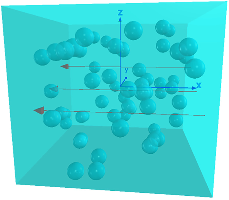
Initially the sensors are deployed in the cuboid. Without loss of generality, we assume that an intruder’s traversing path is a continuously moving trajectory starting at the cuboid’s right face and ending at the opposite face.
We aim to develop a FDDA for underwater strong k-barrier coverage. No special node, such as a leader node or a central unit, is required, all sensors have to rely only on their local information to coordinate their movements. There is also no synchronization among sensors.
Without loss of generality, we assume that the illegal intruders to be detected by underwater sensor barrier move along the direction of cuboid length, as shown in Figure 1, the intruder’s traversing path, that is, the red lines, is a continuously moving trajectory starting at the cuboid’s right face and ending at the opposite face.
Problem statement
According to the aforementioned assumptions, the underwater deployment region is modeled as a cuboid of size
The goal of our work is to devise a FDDA to drive the sensors to move to desired positions, and thus provide maximum-level underwater strong k-barrier coverage. Our problem is how to devise such a FDDA to achieve our goal.
Underwater strong one-barrier coverage
In 2D terrestrial WSNs, a sensor barrier is a chain of sensors from one end of the deployment region to the other end with overlapping sensing zones of adjacent sensors, and the existence of strong k-barrier coverage is equivalent to that of k node-disjoint paths between two vertices in a graph. 12 In other words, 2D k-barrier coverage is constituted with k node-disjoint paths. Notice that one node-disjoint path is actually one-barrier coverage in 2D terrestrial WSNs. Thus, in 2D case, strong k-barrier coverage is constituted with k strong one-barrier coverage, as shown in Figure 2.
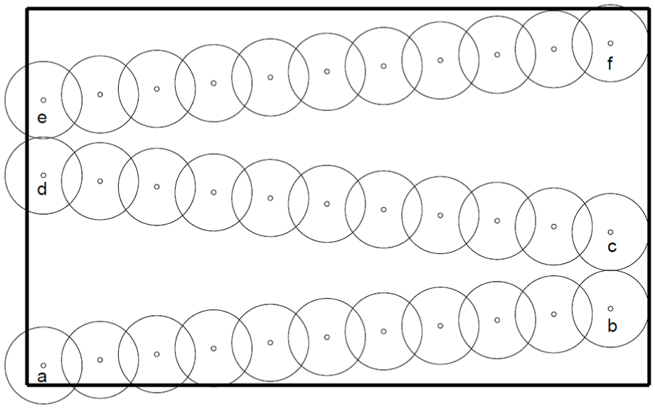
In 2D terrestrial WSNs, a strong k-barrier coverage is constituted with k strong one-barrier coverage (in this example, k = 3). 12
In 3D UWSNs, a sensor barrier is a set of sensors with overlapping sensing zones of adjacent sensors that covers an entire (curly) surface that cuts across the 3D underwater space. 11 Similar to 2D case, an underwater strong k-barrier coverage is constituted with k underwater strong one-barrier coverage, as showed in Figure 3.
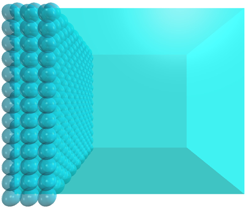
In 3D UWSNs, an underwater strong k-barrier coverage is constituted with k underwater strong one-barrier coverage (in this example, k = 3).
For an underwater strong one-barrier coverage, it is clear that, to minimize the required mobile sensors, the sensors should be repositioned to a vertical plane parallel to the cuboid’s left face. We refer to an underwater strong one-barrier coverage covering such a vertical plane as a layer in this article. Consequently, a feasible approach for constructing an underwater strong k-barrier coverage is to construct it layer by layer. As shown in Figure 3, from left to right, we enumerate the sensor barriers b0, b1, b2, . . ., where b0 is base layer, and the indexes of the other layers increase with the distance from b0. In the following, we analyze how to derive the minimum number of required sensors and the optimal final positions of sensors in each layer.
The minimum number of required sensors
As shown in Figure 3, an underwater strong one-barrier coverage finally completely covers a rectangle plane of size
In terms of the problem on the minimum number of circles required for completely covering a rectangle, Kershner 37 had proved that the regular triangular tessellation is the optimal tessellation, which makes a set of regular hexagons completely cover a 2D plane without any overlap, as shown in Figure 4. According to the context of our work, if we place a sensor in the center of each regular hexagon of circumradius r, where r is sensor’s sensing radius, the sensing range of all sensors will completely cover the rectangle. Consequently, we have Theorem 1 as follows.

A rectangle that is completely covered by minimum regular hexagons.
Theorem 1
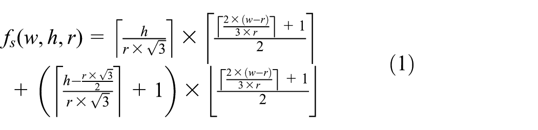
The minimum number of sensors with sensing radius r required for completely covering a rectangle of size
Proof 1
As shown in Figure 4, given a rectangle of size

In the width direction, the number of rows of odd-number columns is

The number of rows of even-number columns is
Combining equations (2)–(4), we obtain the minimum number of regular hexagons

The above derivation obtains the minimum number
The optimal final positions of sensors
According to previous analysis, once we place a sensor in the center of each regular hexagon, the sensing range of all sensors will completely cover the rectangle. Actually, for each layer, the optimal final positions of sensors are the center points of regular hexagons, whose x coordinates equal to the layer’s x coordinate. In the following, we derive
As shown in Figure 4, we first obtain the y coordinate of each column via equation (6), where i denotes the

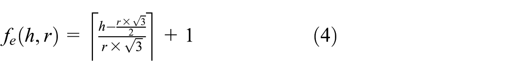
Then we get the z coordinate of each point row by row. For odd-number columns, h denotes the cuboid height, r denotes the sensing radius, j denotes the

For even-number columns, h denotes the cuboid height, r denotes sensor’s sensing radius, j denotes the

Combining equations (7) and (8), we have

Finally, by combining the layer’s x coordinate, we obtain the optimal final positions
FDDA
In this section, we propose a fully FDDA for constructing maximum-level underwater strong k-barrier coverage with available mobile sensors.
Main idea
The main idea of the proposed algorithm is to construct underwater strong k-barrier coverage layer by layer. For the sake of clearness, we introduce two important concepts. One is constructed layer, on which no sensor has adjacent vacant positions resided on the same layer as itself, in other words, this layer has been constructed. The other is constructing layer, on which there are still some vacant positions to be occupied by sensors, in other words, this layer is being constructed. Since underwater strong k-barrier coverage is to be constructed layer by layer, there is only one constructing layer at the same time during the construction process. For example, base layer
Furthermore, in order to finally create a single connected barrier component (i.e. an UWSN) to satisfy the management requirement of application, we set the distance between adjacent sensors as
The proposed algorithm provides the interleaved execution of three main activities, namely, vertical movement, vacant position processing, and parallel movement. Before starting the execution of the three main activities, each sensor performs an initial movement aiming to move to the closest centerline, which is perpendicular to the base layer and pass through the hexagon center point of each layer, as shown in Figure 5.

The centerlines are perpendicular to the base layer and pass through the hexagon center points in each layer. As shown in this figure, the red dash lines are centerlines.
Initial movement
In order to make each movable sensor move orderly in underwater space, and thus ensure that the proposed algorithm performs effectively and efficiently, each sensor initially moves to the centerline closest to itself by means of parallel moving. It is worth noting that after the initial movement, all sensors are on the centerlines, and by executing the proposed algorithm, each sensor only moves along the centerline or moves to another centerline by means of parallel moving. We will obtain a sensor’s closest centerline in the next subsection.
Vertical movement
The vertical movement activity is twofold. On one hand, in order to increase the connectivity of the network, each movable sensor moves toward base layer by means of vertical moving if it has no sensor in radio proximity, which is resided on the same centerline and closer to base layer than itself. The movement is stopped as soon as such a sensor is found or the base layer is reached. On the other hand, to ensure that all sensors can finally move their desired positions, each movable sensor with a distance less than
Vacant position processing
There are three aspects in vacant position processing. First, to notify the other sensors of the vacant positions resided on the constructing layer, each sensor periodically detects and broadcasts its adjacent vacant positions resided on the same layer as itself in the network. Second, each sensor receives and processes the vacant positions broadcasted by other sensors. It is worth noting that, in order to manage the vacant positions resided on the constructing layer, each sensor maintains a vacant position queue, where the vacant positions are sorted by the distance between vacant position and the sensor in an ascending order. Finally, by leveraging the data cached in vacant position queue, a sensor makes its movement decision.
Parallel movement
In this activity, a movable sensor first confirms whether it is closest to the vacant position at the head of its vacant position queue. If it is the closest one, it moves to the desired position by means of parallel moving then starts the vertical movement activity. If otherwise, it terminates this activity and gives start to the vertical movement activity. The approach to find the closest vacant position for a movable sensor will be given in the next subsection.
Details of the proposed algorithm
In this subsection, we describe the details of the proposed algorithm FDDA. We first show the detail of the initial movement, and then present the details of three main activities of FDDA. Figure 6 shows a flowchart of these activities.
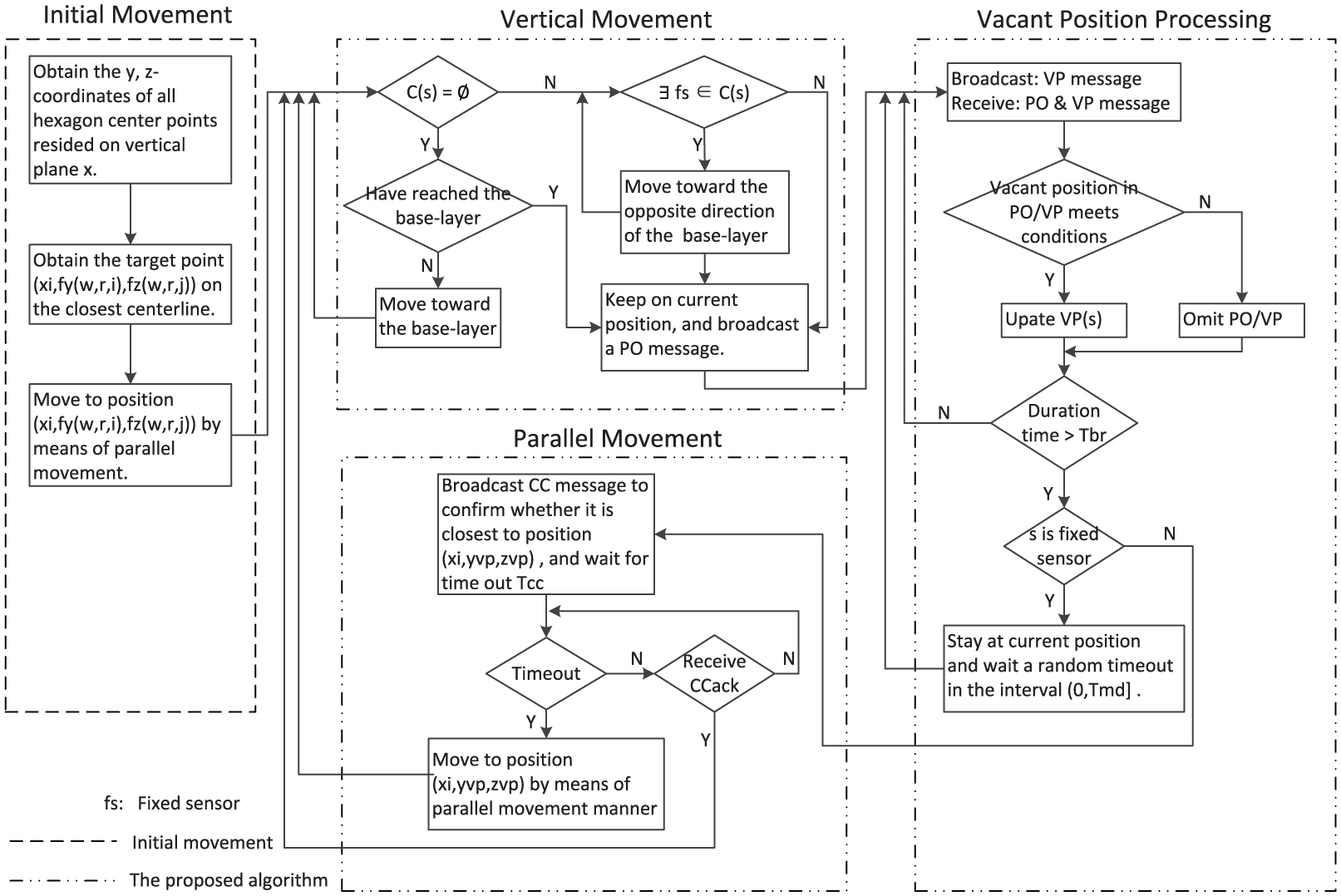
Flowchart of the initial movement and the proposed algorithm executed by a sensor s with initial position
Initial movement
Initial movement is significant since it places the sensors in an orderly manner on the centerlines and thus ensures that the proposed algorithm performs effectively and efficiently. For each sensor, the key to initial movement is to find the centerline closest to it. According to the previous analysis, the centerlines are perpendicular to the base layer and pass through the hexagon center points in each layer, where the positions
As shown in Algorithm 1, for a sensor

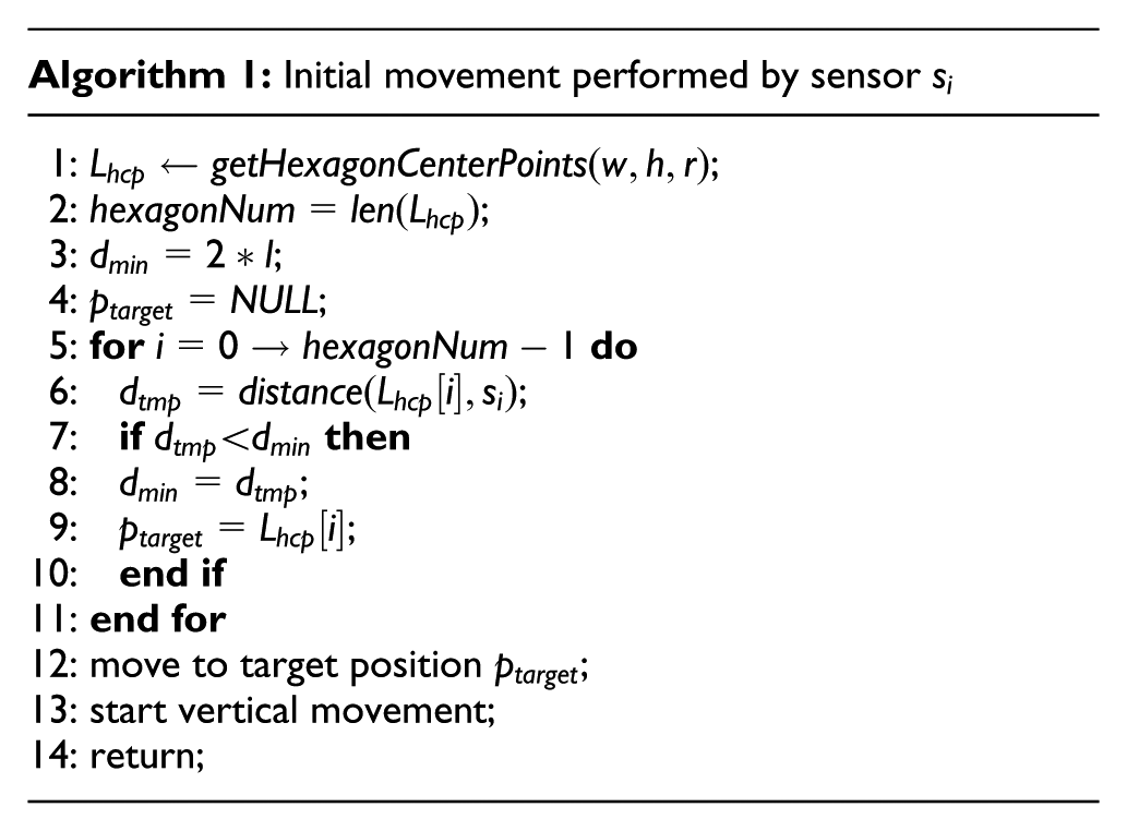
Once a sensor
According to the pseudocode of Algorithm 1, its computational complexity is proportional to the number hexagonNum of hexagon center points in a layer, while
Vertical movement
The goal of vertical movement is to increase network connectivity, to avoid the presence of isolated sensors and to ensure that all sensors can finally move to their desired positions. Since all sensors are on the centerlines perpendicular to the base layer after initial movement, and the vertical movement requires the sensors to move along the centerlines in the moving process, each sensor only needs to consider sensors in radio proximity (i.e. the sensors with a distance less than
The vertical movement is based on the following described protocol. As shown in Algorithm 2, for a sensor

Finally, if sensor
According to the pseudocode of Algorithm 2, its computational complexity is related to a sensor’s movement distance. In the worst case, a sensor may move from the right face to the left face of the cuboid, we assume that it stops to check the conditions at line 1 and line 6 every M meters, thus the while loop in Algorithm 2 may be executed at most
Vacant position processing
Vacant position processing involves three aspects, namely, vacant position broadcasting, vacant position receiving, and vacant position leveraging. A sensor keeps on its current position while performing this activity, it first periodically broadcasts and receives vacant position message with a duration time
As shown in Algorithm 3, for a sensor

By means of the above protocol, each sensor maintains a vacant position queue, where vacant positions are all resided on the constructing layer (the vacant positions resided on the constructing layer have the smallest x coordinate, and consequently, they are finally cached in vacant position queue according to the above protocol) and sorted by the distance between vacant position and the sensor in an ascending order.
After the expiration of time
If sensor
It is worth noting that, in real-life applications, we can optimize the vacant position broadcast through following two strategies to reduce the communication cost caused by broadcast.
Once a sensor
Once a sensor
According to the pseudocode of Algorithm 3, its computational complexity is related to two parameters,
Parallel movement
From the perspective of reducing energy consumption, a movable sensor prefers to move to a vacant position closest to itself. As the previous description, the vacant positions in a sensor’s vacant position queue are ordered by the distance between vacant position and the sensor in an ascending order. It is clear that, for sensor
As shown in Algorithm 4, for a movable sensor
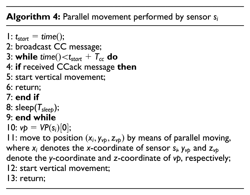
According to the pseudocode of Algorithm 2, its computational complexity is related to two parameters,
Performance evaluation
In this section, we evaluate the performance of the proposed algorithm FDDA through simulations. We first validate that the proposed algorithm has a guaranteed termination that all sensors stop moving after a finite time and provide maximum-level underwater strong k-barrier coverage in three representative scenarios. Then we show that the proposed algorithm has the capability of self-healing. Finally, we compare FDDA with Hungarian algorithm 39 which obtains the optimal total movement distance of all sensors, and HungarianK, 31 which consumes less computation time than Hungarian. The simulation parameters are described as follows.
Considering that the average ocean depth is 3795 m,
40
and some commercial magnetic sensors can detect submarines at distances of several hundred meters.
11
We assume that the underwater space where the underwater strong k-barrier coverage to be constructed is a cuboid of length
Guaranteed termination
The proposed algorithm has no special requirements for the initial deployment of the sensors, they can be initially deployed in any area of the cuboid. For clearness, we classify the initial deployment of sensors into three representative scenarios, namely, global deployment where the sensors are initially deployed throughout the cuboid, local deployment where the sensors are initially deployed in local area of the cuboid, and point deployment where the sensors are initially placed at a point in the cuboid (although, in real-life applications, it is impossible to make all sensors gather at one geographic position, in order to provide insights into this extreme scenario, we consider the point deployment scenario as well). In each scenario, 500 sensors are initially randomly deployed in the cuboid. In this subsection, we validate that all sensors stop moving after a finite time and finally provide maximum-level underwater strong k-barrier coverage in the three representative scenarios.
In the first scenario, the sensors are initially randomly deployed throughout the cuboid, as shown in Figure 7(a). Each sensor starts the proposed algorithm after completing its initial movement. It is worth noting that the sensors are independent of each other and perform the proposed algorithm asynchronously. By vertical movement, the sensors move toward the base layer and form several network components by connecting to each other. The sensors in different network components construct underwater strong k-barrier coverage simultaneously. Figure 7(b)–(d) shows the different instants obtained by the proposed algorithm, which show that, by executing the proposed algorithm, the sensors construct underwater strong k-barrier coverage layer by layer. Finally, Figure 7(e) shows that all sensors stop moving after a finite time, and the sensors finally provide maximum-level underwater strong k-barrier coverage, that is, k = 3.

In the first scenario, the sensors are initially deployed throughout the cuboid. By executing the proposed algorithm, all sensors stop moving after a finite time, and the sensors finally provide maximum-level underwater strong k-barrier coverage, that is, k = 3: (a) initial deployment, (b) constructing layer b0, (c) constructing layer b1, (d) constructing layer b2, and (e) all sensors stop moving at time 3696 s.
Figure 8(a) shows the initial deployment of sensors in the second scenario, Figure 8(b)–(d) shows the different instants obtained by the proposed algorithm in the second scenario, while Figure 8(e) shows that all sensors stop moving after a finite time, and the sensors finally provide maximum-level underwater strong k-barrier coverage, that is, k = 3. Different from the first scenario, where all sensors move toward the base layer to construct the underwater strong k-barrier layer by layer, in the second scenario, there are some sensors that move toward the opposite direction of the base layer in the construction process, Figure 8(b)–(d) clearly shows this behavior of the sensors. In Figure 8(b), base layer b0 is the constructing layer, a set of movable sensors, which detect that there are fixed sensors in their radio proximity, move toward the opposite direction of the base layer until they reach layer b1. Likewise, in Figure 8(c) and (d), a set of sensors move to layer b2 and layer b3, and thus complete the construction of underwater strong k-barrier coverage.

In the second scenario, the sensors are initially deployed in local area of the cuboid. By executing the proposed algorithm, all sensors stop moving after a finite time, and the sensors finally provide maximum-level underwater strong k-barrier coverage, that is, k = 3: (a) initial deployment, (b) constructing layer b0, (c) constructing layer b1, (d) constructing layer b2, and (e) all sensors stop moving at time 1673 s.
Figure 9(a) shows the initial deployment of sensors in the third scenario, where all sensors are placed at a point in the cuboid. By executing the proposed algorithm, the sensors move toward the base layer one by one, and then complete the construction of the underwater strong k-barrier coverage layer by layer. Figure 9(b)–(d) shows the different instants obtained by the proposed algorithm, while Figure 9(e) shows that all sensors stop moving after a finite time, and the sensors finally provide maximum-level underwater strong k-barrier coverage, that is, k = 3. Different from the first two scenarios where the sensors form several network components by vertical movement, there are only one network component in this scenario that makes the proposed algorithm in this scenario spend more time than the first two scenarios.

In the third scenario, the sensors are initially placed at a point in the cuboid. By executing the proposed algorithm, all sensors stop moving after a finite time, and the sensors finally provide maximum-level underwater strong k-barrier coverage, that is, k = 3: (a) initial deployment, (b) constructing layer b0, (c) constructing layer b1, (d) constructing layer b2, and (e) all sensors stop moving at time 6526 s.
Self-healing capability
In this subsection, we aim to validate whether the proposed algorithm is able to self-heal underwater strong k-barrier to deal with sudden sensor failures.
In real-life underwater applications, some sensors may suddenly cease to work due to malfunction or an attack, which makes the deployed sensors unable to provide maximum-level underwater strong k-barrier coverage. In this simulation, we consider such a scenario after final deployment, 500 sensors provide maximum-level underwater strong k-barrier coverage (i.e. k = 3), but a set of sensors suddenly stop working thanks to an attack, which makes the remaining sensors unable to provide maximum-level underwater strong k-barrier coverage. We assume that a sensor is able to detect faults of its adjacent sensors resided on the same layer as itself. According to previous description, the position of the malfunction sensor will be recognized as a vacant position by its adjacent sensors, and as a result, this vacant position will finally be broadcasted in the network according to the protocol described in Algorithm 3.
Without loss of generality, we assume that 11 failure sensors are on the edge of the barrier for clear presentation, as shown in Figure 10(a). The remaining deployed sensors only provide strong one-barrier coverage after an attack. By executing the proposed algorithm, a set of adequate sensors automatically move to the desired positions, and heal the underwater strong k-barrier layer by layer. Finally, the remaining 489 sensors provide maximum-level underwater strong k-barrier coverage again, that is, k = 3. Figure 10(b)–(d) shows the different instants of the self-healing process.

By self-healing, a set of adequate sensors move to their desired positions, finally the deployed sensors provide maximum-level strong k-barrier coverage again, that is, k = 3: (a) a collection of sensors stop working due to an attack, which makes the deployed sensors only provide strong one-barrier coverage in this example, (b) layer b0 is healed, (c) layer b1 is healed, (d) layer b2 is healing, and (e) the deployed sensors provide maximum-level underwater strong k-barrier coverage, that is, k = 3.
Comparison with other algorithms
As far as we know, the proposed algorithm FDDA is the first FDDA for constructing maximum-level underwater strong k-barrier coverage with available mobile sensors. To evaluate the performance of FDDA, we compare it with a classic centralized approach, namely, Hungarian algorithm, 39 which minimizes the total movement distance of all sensors, and HungarianK 11 consumes less computation time than Hungarian. We assume that all sensors are initially randomly deployed throughout the underwater space. The number of available sensors ranges from 100 to 800 with an increment of 100 each time. Four performance metrics are considered in the simulation experiments, namely, average movement distance of each sensor, maximum movement distance of all sensors, total movement distance of all sensors, and duration of the construction of underwater strong k-barrier coverage.
Figure 11 shows the average movement distance achieved by FDDA, Hungarian, and HungarianK. Three algorithms show that the average movement distance decreases with the increasing number of sensors. This is because more sensors locate closer to their final positions as the number of sensors increases. Although, in Hungarian algorithm, each sensor moves from its initial position to its final position along a straight line that minimizes its movement distance, the average movement distance of Hungarian algorithm is only 28% lower than that of the proposed algorithm FDDA.

Average movement distance versus number of sensors.
Figure 12 shows the maximum movement distance of all sensors achieved by FDDA, Hungarian, and HungarianK. Three algorithms show a gentle decreasing behavior of the maximum movement distance as the number of sensors increases. This is because more sensors locate closer to their final positions as the number of sensors increases. HungarianK obtains a best result which is about 35% lower maximum movement distance than FDDA, this is because under HungarianK algorithm each sensor moves from its initial position to its final position along a straight line, while most of the sensors in the proposed algorithm FDDA move to their final positions by means of vertical or parallel moving according to their movement decisions, which makes them move along zigzag route.

Maximum movement distance versus number of sensors.
For the total movement distance of all sensors, although the Hungarian algorithm is the optimal solution that achieves the minimum total movement distance, the proposed algorithm FDDA also presents an acceptable result, as shown in Figure 13, the optimal total movement distance of Hungarian algorithm is only 28% lower than that of FDDA.
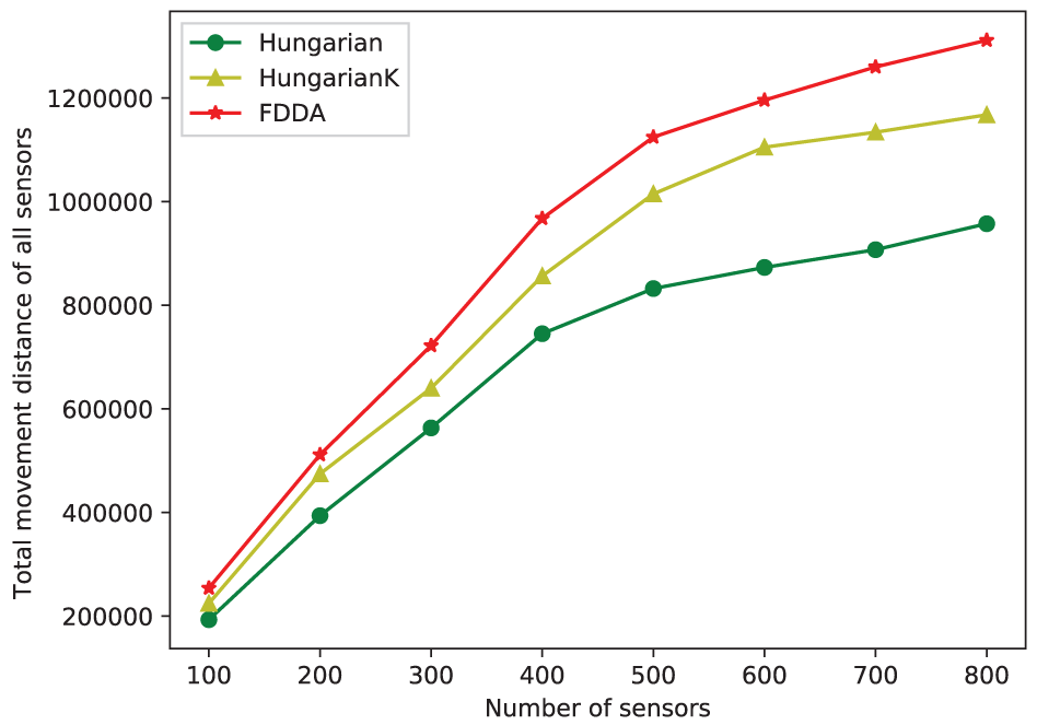
Total movement distance versus number of sensors.
The duration depicts the length of the time that the construction of the underwater strong k-barrier coverage continues. For Hungarian and HungarianK, the duration includes the computing time consumed by the central unit to assign a final position per sensor, and movement time consumed by all sensors to move from their initial positions to their final positions along a straight line. While for FDDA, the duration mainly includes the movement time consumed by all sensors to move from their initial positions to their final positions along a zigzag route. As shown in Figure 14, the durations of Hungarian and HungarianK increase sharply as the number of sensors increases, while the increase in the duration of FDDA is relatively flat. This is because the optimal computational complexity of Hungarian algorithm is

Duration time versus number of sensors.
Conclusion
In this article, we devised a FDDA for constructing maximum-level underwater strong k-barrier coverage with available mobile sensors in 3D underwater environment. We first analyzed how to form underwater strong one-barrier coverage with minimum mobile sensors, based on which we obtained the minimum number of sensors required for constructing underwater strong one-barrier coverage and the corresponding optimal final positions of these sensors. Then, we proposed a FDDA for constructing maximum-level underwater strong k-barrier coverage with available mobile sensors in 3D underwater environment. By extensive experiments, we showed that the proposed algorithm has a guaranteed termination that all sensors stop moving after a finite time and provide maximum-level underwater strong k-barrier coverage, and the proposed algorithm is able to self-heal the underwater strong k-barrier coverage to deal with sudden sensor failures. Experimental results showed that the proposed algorithm outperforms both Hungarian and HungarianK in terms of duration and achieves performance close to them with respect to three performance metrics, namely, average movement distance of each sensor, maximum movement distance of all sensors, and total movement distance of all sensors.
Footnotes
Handling Editor: Feng Hong
Declaration of conflicting interests
The author(s) declared no potential conflicts of interest with respect to the research, authorship, and/or publication of this article.
Funding
The author(s) disclosed receipt of the following financial support for the research, authorship, and/or publication of this article: This work was supported in part by Major Omnibus Reform Project (Information and Computing Science) of China under Grant No. 82616611, National Science Foundation of China under Grant Nos 61373158 and 61671213, Guangzhou Key Lab of Body Data Science under Grant No. 201605030011.