
Abstract
Numerous construction projects have caused the rapid development of the drilling industry in China. Various types of drilling equipment are widely used in the projects and have to be designed quickly to meet the increasing demand. Based on the initial modeling, macro recording, program compilation, and interface development in the SolidWorks and Visual Basic environment, this article introduces a new method of automated design using specialty automated design software for the chuck of core drilling rigs. This secondary developed software can quickly perform design for the parts and assembly of the chuck after inputting only several parameters of the work requirements. This software simplifies and automates the design process to a great extent by embedding the laborious computing tasks into the computer program and eliminating manual drafting work. This makes the designer focus more on the work requirements, instead of modeling, drafting, calculating, and so on. This can decrease the repetitive work of mechanical designers and increase their working efficiency.
Introduction
With the rapid development of computer technology, design technology has been greatly promoted. Since the Sketchpad project was used to create and manipulate graphic images on a cathode ray tube (CRT) display in real time in the 1960s, design professionals have been through a series of changes of design methods, 1 that is, manual drawing, computer-aided drafting (CAD), and computer-aided design (parametric design, variable design, feature design, etc.). In the near future, automated design oriented to product application will take a leading position within the design field.
Automated design is an advanced design concept and goal that people have been pursuing for many years.2,3 It includes many new technologies and ideals such as profiling, sketching, dimension drive, variable design, parametric design, feature design, rationality checking, interference checking, and dynamic navigation. Therefore, it can help the designer to decrease or eliminate time-consuming work, such as computing and drawing, thus focusing on design ideas and creation. 4
Many modeling software programs based on parametric design, variable design, and feature design declare that the designer can just focus on the design sequence, but not the drafting, especially within the three-dimensional (3D) area.5–8 That is to say, the designer can realize “what he or she sees is what he or she gets” in a parametric and feature modeling environment, thus devoting attention to exerting his or her imagination to design a more perfect product and decrease the whole design time. These software programs include SolidWorks, Pro/Engineer, and Unigraphics.
However, there are still many time-consuming tasks to do within the product design sequence. For example, the designer has to look up the relevant specifications and manuals to choose the right parameters, such as working coefficients, standard gear modules, and loading coefficients for a gear transmission and then insert them into the computing formulas and expressions to determine the optimized values for the structure dimensions and other parameters. This complicated computing sequence not only consumes much of the designer’s time and energy, but it also allows some inevitable errors.
Automated design9–11 is a brand new method of design in the field of drilling rig design. Its aim is to simplify the design sequence to the greatest extent, thus letting the user of the product have the capability to design the product, even though he or she is not an expert in the field of machine design. Take the whole drilling rig design job as an example. The designer only needs to input some application properties, such as the diameter and depth of the wellbore, into a specially developed software program. Then, the software will finish all computing and drawing tasks. As a result, the designer can focus more on the work requirements without performing drafting or design work for the drilling rig itself.
In general, the designer can realize “what he or she wants is what he or she gets” within a simple friendly interface using the automated design.
The large number of construction projects in China facilitates the rapid development of the drilling industry. A wide variety of drilling equipments are used in the projects. 12 Although design automation has made some progress, the automated design of drilling rigs is still very rare. Aimed to this question, the secondary development techniques for SolidWorks and Visual Basic (VB) programming language will be combined to present a kind of brand new way of automated design in the field of chuck design of core rig. The parts and assembly of the chuck for drilling rig will be completed using the specialty developed design program. It is the first step for realizing real automated design in the field of drilling rig design and lays a strong foundation for the whole drilling rig design in the near future.
Methodology and tools used in the automated design of drilling rigs
Based on a visual programming language, automated design will execute the computing sequence using the compiled computer program with all relevant formulas and expressions, line graphs, and lookup tables for parameters built in. Based on a 3D parametric or feature modeling software, automated design will complete the element drawing, part drawing, and assembly drawing after the secondary development of the modeling software. The programming language could be VB or Visual C++, and the modeling software could be SolidWorks, Pro/Engineer, or Unigraphics.
As a new trial, VB and SolidWorks were employed here to automatically design the chuck assembly of a core drilling rig. The interface developed using VB is very friendly and simple, and SolidWorks is a specialty secondary development tool of the VB Application. 13 Both of them have the same programming system. In addition, the series table of SolidWorks can simplify the design process for products with similar topology relationships. 14
VB integrated development environment
The time-consuming computing sequence for chuck design and the friendly interface are developed within the VB integrated development environment. 15
VB is a high-level programming language which evolved from the earlier DOS version called BASIC. It is a very easy programming language to learn. The code looks a lot like the English language.
It is also a well-developed programming language, and supporting resources are available everywhere. Currently, there are many versions of VB existing in the marketplace, but the most popular one and the one still widely used by many VB programmers is VB 6.0.
VB is a VISUAL and event-driven programming language. Programming is done in a graphical environment. The user just needs to drag and drop any graphical object anywhere on the form, and the object’s color can be changed at any time using the properties window. As a result, the interface developed using VB is very friendly and beautiful.
A VB program is made up of many subprograms. Each has its own program code and can be executed independently. At the same time, they can be linked together in one way or another.
Modeling in SolidWorks
The basic model of the chuck assembly is created using the modeling function of SolidWorks. SolidWorks provides complete and intuitive 3D solutions for product design, analysis, and data management. 16
As popular 3D design software, SolidWorks CAD helps design teams around the world bring their ideas to life. It is easy to learn, easy to use, and easy to navigate, letting users concentrate on their designs, not their CAD software itself. Using SolidWorks, the user will be able to quickly plot a sketch, execute feature modeling and dimensioning, and even generate the engineering drawings for the parts and assembly of a drilling rig.
SolidWorks Visual Basic for Applications
Microsoft Visual Basic for Applications (VBA) is a set of secondary development programming tools based on Microsoft VB. It is embedded in the SolidWorks software. 14
The quickest and easiest way to start programming is to record a SolidWorks macro for a modeling process of a part in the SolidWorks environment. Recorded macros are saved as .swp files. Then, the user can modify the macro in Microsoft VBA or VB to meet the work site’s needs.
The SolidWorks design table of series parts
The design table of series parts of SolidWorks is used to design parts that have the same structure and different sizes. 17 For different diameter drilling pipes, the parts in the chuck have the same structure and different sizes. They can be modeled with the design table of series parts. Part models are derived from the design tables of series parts to achieve design rapidly. There is a design table of series parts connected with Office Excel. The size of the parts is determined by the design table of series parts, which relates sizes to a key element.
The design table embedded in SolidWorks is a powerful way to manipulate properties, features, sketches, drawings, and assemblies. It is an Office Excel spreadsheet, which is used to produce multiple configurations for a part or assembly. The specific steps are as follows: first, a new design table of series parts is inserted, and second, the related size information is inputted into the design table of series parts. After the second step, the model will automatically generate a new configuration.
Communication between VB and SolidWorks
VB will communicate with SolidWorks by importing the “SolidWorks 2008 Type Library” of SolidWorks 2008. This communication will import the objects of SolidWorks application program interface (API) into the VB running environment. 18 The API contains hundreds of functions that the user can call from VB, VBA, Visual C++, or SolidWorks macro files. These functions provide direct access to SolidWorks functionality.
Automated design of the chuck
A core drilling rig consists of the slipping clutch, transmission case and transfer case, clinostat and chuck, lifter, impact mechanism, vibrating mechanism, rig base, travel mechanism, and hydraulic system. 19
The chuck is an important part of the core drilling rig. The performance of the chuck directly affects the entire rig performance, drilling efficiency, and drilling quality. The chuck is used for clamping the drill pipe and transmitting torque and axial force to drive drill pipe rotation and feed.
Figure 1 illustrates how the chuck works. The clamping parts of chuck are three slips. Force amplifier mechanism composed of slope is used to transmit the spring force F to slip to clamp the pipe. The dish spring is pushed by hydraulic power. 20

The operation principle of chuck.
The structure of chuck is illustrated in Figure 2. It has three slips, a slip recess, a clip, several dish springs, an oil pump loop body, a shell, a top cover, and a bottom base.
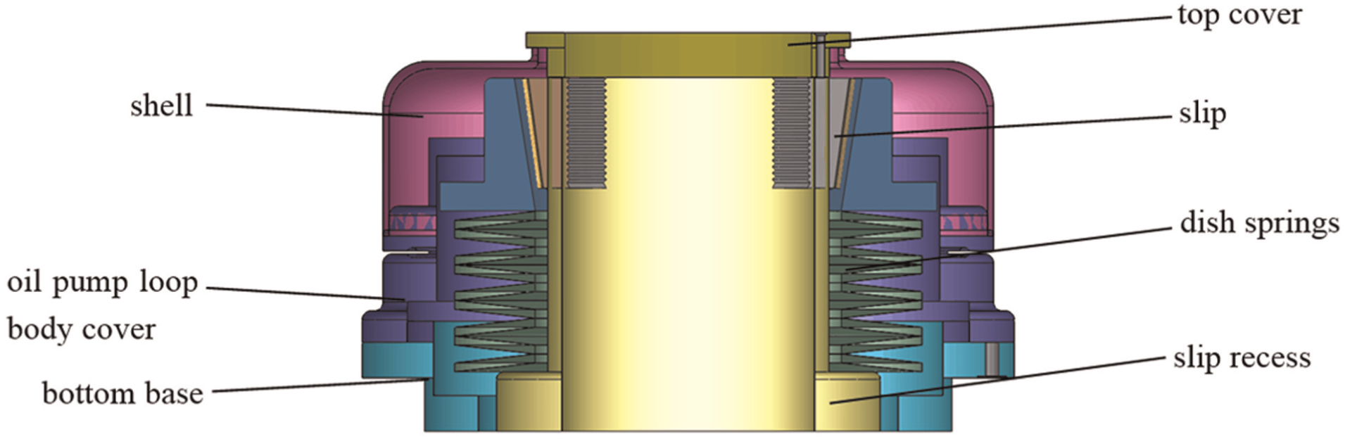
The structure of chuck.
Automated computing of the basic chuck parameters
The structural parameters of the hydraulic chuck are determined by the clamping diameter of the drill pipe and the maximum working load. The basic performance parameters are the maximum load and equivalent clamping force. 19
All known independent parameters 21 in the formulas for computing basic parameters for chucks are chosen to create a user inputting form in the VB environment. The formulas are programmed into the computing code.
After the structural work parameters are inputted, both basic performance parameters of the chuck can be achieved by the automated computing program automatically, so that the most time-consuming manual design tasks are eliminated.
Maximum load—Pmax
Chuck work capacity is determined by the maximum load at the work conditions.22,23 There are two types of working conditions for chucks: one is the condition of strong pull, and the other is the normal drilling. The chuck size is determined by the maximum load in the two conditions:
For the condition of strong pull, chuck load Pb is computed as equation (1)

where α is the safety factor, and α is 1.25–1.6. Psmax is the maximum uplift force for feeding mechanism.
For the normal condition, chuck load Pg is computed as equation (2)

where Px is the axial force acting on the drilling pipe, taken as the maximum feeding force for increasing (or decreasing) pressure, Py is the peripheral force acting on the drilling pipe: Py = 2·Mn/d, Mn is the output torque of the clinostat at the second speed, and d is the diameter of the drilling pipe.
Comparing the two values, Pmax is the larger one, as seen in equation (3)

Equivalent clamping force Q
To make the chuck work reliably, the design key is to reasonably determine the chuck clamping force. The equivalent clamping force Q is the clamping force for bearing Pmax as shown in equation (4)
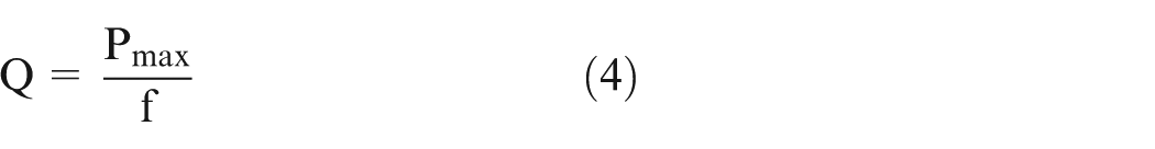
where f is the friction coefficient between the slips of the chuck and the drilling pipe.
According to the relationships among these parameters, the flow chart for computing the basic parameters of the chuck is illustrated in Figure 3. The user interface is illustrated in Figure 4.
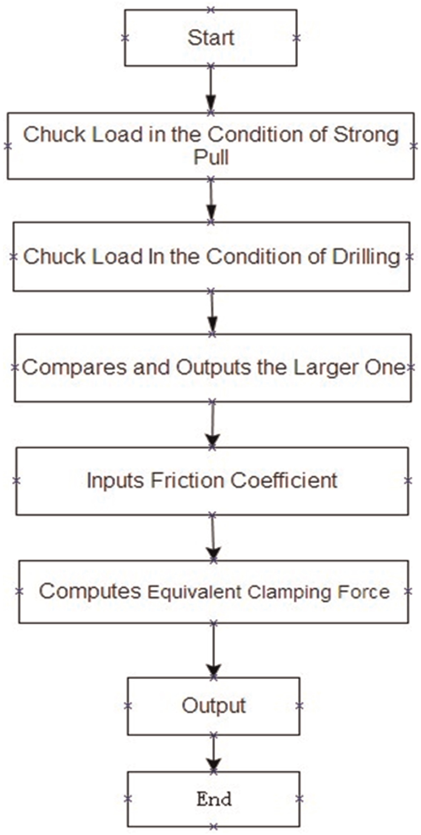
The flow chart for computing the basic parameters of the chuck.
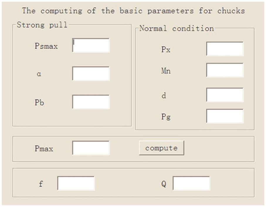
The user interface for computing the basic parameters of the chuck.
When the maximum working load and pipe diameter are given, the chuck can be designed.
Automated design of slips
A slip type hydraulic chuck is usually used in the core drilling rig. It transfers the axial force and torque by the friction between the slips under the action of positive pressure.
The radial direction movement of slip Δr indicates the clamping range of the chuck. Commonly, Δr = 1–2 mm. The cant force amplifier mechanism is used to execute the clamping of the slip.
The angle of cant α is the most important design parameter. The relation between the force and α is shown in equations (5) and (6).


where
The axial movement

Cant movement.
There are three slips in the chuck of the core drilling rig. The size of the slips is determined by the diameter of the drilling pipes and the clamping force. The automated design steps for the slip structure are as follows:
According to the topology relationship of the slips, 19 the basic 3D solid model is built in SolidWorks 2008, as illustrated in Figure 6. Only two design parameters are needed to be changed for controlling the change of the model. One (column B in Figure 7) is the diameter dimension of sketch 1 that is matched with the diameter of drill pipe, and the other (column C in Figure 7) is the diameter dimension of sketch 4 for the teeth on the slip. Other dimensions belong to driven dimension or fixed dimension that is embedded into the original model. In addition, it should be noted that the sequence number of sketches depends on the sequence of the features modeling in the model (the same below).
The operation code for modeling is obtained by recording a macro within the VBA environment of SolidWorks while the slips model is building.
According to the relationship between the size of a slip and the drilling pipe diameter,19,20 the design parameters table of series parts for six kinds of drilling pipe radii is established, as illustrated in Figure 7, as the diameters of popular drill pipes are 51, 61, 43, 81.8, 54, and 48 mm.
The recorded macro of operation code is copied into the chuck inputting form developed by VB as its partial program codes. They can be edited and modified to satisfy new program requirements.
The computing program for the slip design is edited in the VB environment.
After both the operation code and computing program are compiled and debugged, the slips model can be obtained automatically in terms of the diameter of the drilling pipe inputted in the chuck inputting form.

The 3D solid model of the slip.
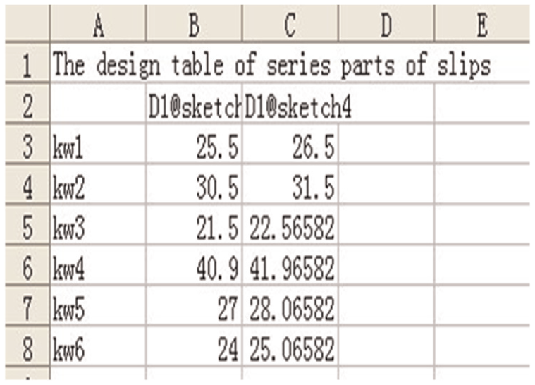
The design table of series parts of the slip.
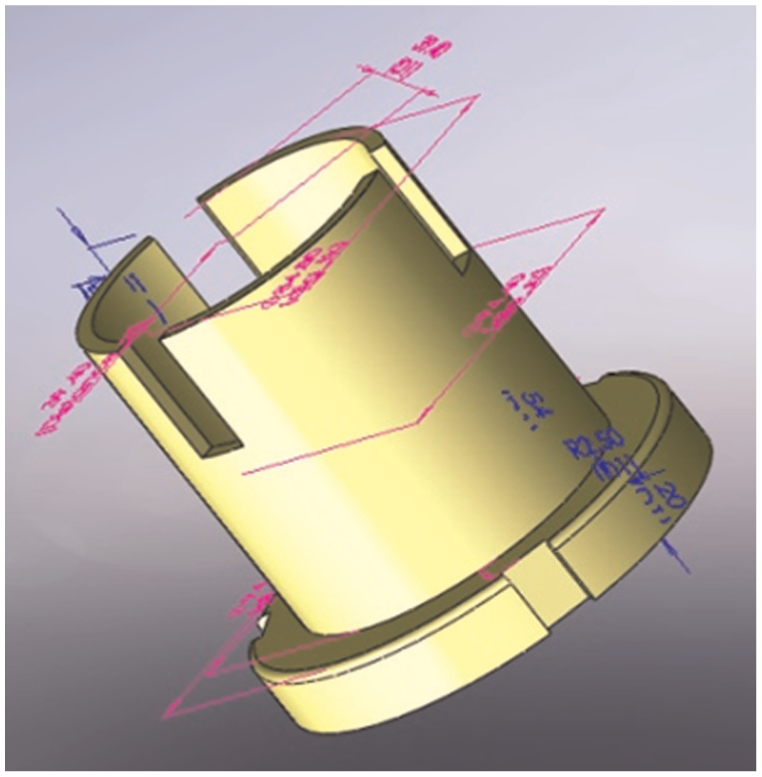
The design result of the slips for the 43-mm-diameter drilling pipe is illustrated in Figure 6.
Automated design of slip recess
The slip recess is used to limit the radial movement of three slips. Automated design of slip recess for the 81.8-mm-diameter drilling pipe is illustrated in Figure 8.
The 3D solid model of the slip recess.
Its size is determined by the size of the slips. Inner diameter of the slip recess is 6–10 mm larger than the diameter of the drilling pipe. Other structure dimensions of the slip recess depend on its inner diameter, as listed in Figure 9.
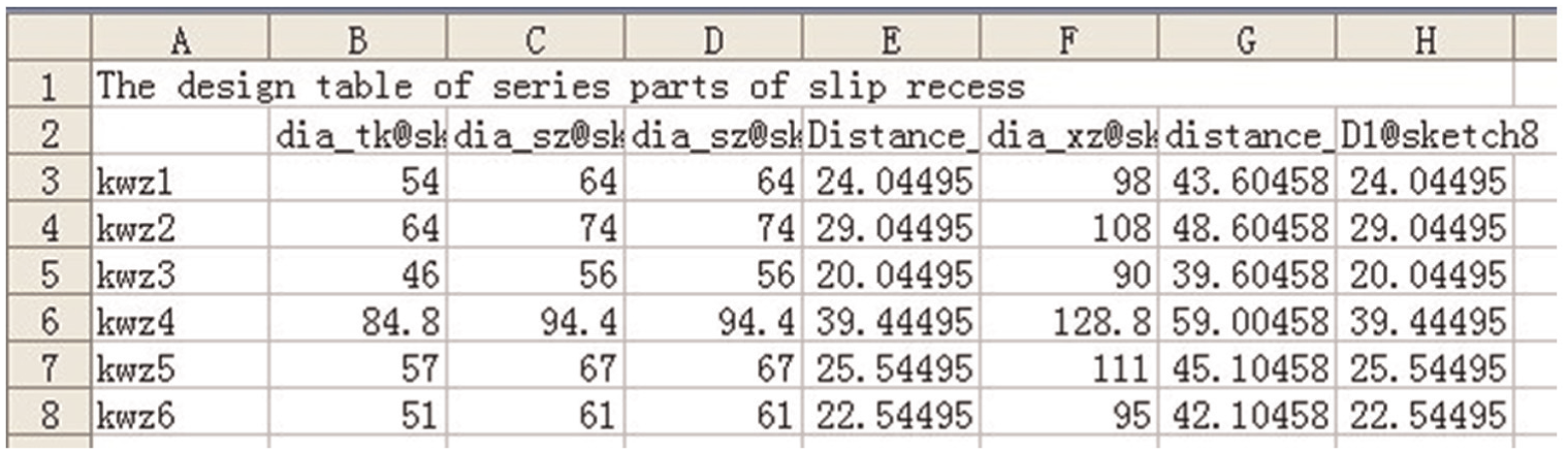
The design table of series parts of slip recess.
In fact, both the selection of the parameter and modeling process, to great extent, depend on the designer. Take Figure 9 as an example, seven design parameters from various sketches can be employed to change the model: (1) the diameter of sketch 7 in column B (i.e. the inner diameter) matched with the drilling pipe, (2) the diameter of sketch 4 in column C (i.e. the outside diameter of the slip recess), (3) the diameter of sketch 2 in column D equaled the diameter of sketch 4, (4) the distance of sketch 8 in column E is the distance between the center of slip recess and the inner edge of slips, (5) the diameter of sketch 1 in column F is the diameter of bottom base, (6) the distance of sketch 9 in column G is the distance between the center of slip recess and the bottom opening, and (7) the diameter of sketch 8 in column H is the diameter of array for the upper opening.
Other dimensions also belong to driven dimension or fixed dimension that are embedded into the original model as that of the slip. Furthermore, the design process for the slip recess is completely similar to that of the slip.
Automated design of the clip
The clip is used to facilitate the hydraulic oil actively flowing into the oil circuit of the chuck for keeping the chuck in the self-locking state. The automated design of the clip for 43-mm-diameter drilling pipe is illustrated in Figure 10.

The 3D solid model of the clip.
The size of the clip depends on the diameter of the drilling pipe. The design table in Figure 11 lists the size of clips according to the pipe diameter. Only one design parameter is needed to control the change of the model, that is, the radius of sketch 1. Other dimensions are embedded into the original mode. The process of automated design for the clip is similar to that of the slip.

The design table of series parts of the clips.
Automated design of the dish springs
Two types of springs can be used in the chuck: the dish spring and the cylinder helix spring. The dish springs illustrated in Figure 12 for the 51-mm drilling pipe are usually used in the normally closed chuck of the core drilling rig.

The 3D solid model of the dish spring.
According to axial force F and diameter of outer diameter of slip recess, the dish spring is designed. The size of springs is listed in Figure 13. Only one design parameter is needed to control the change of the model, that is, the radius of sketch 1. Other dimensions are embedded into the original mode.

The design table of the dish springs.
Automated design of oil pump loop body
The oil pump loop body is used to transfer hydraulic oil and protect the parts inside the chuck. Inside the body, there are loop circuits for hydraulic oil flowing. Although its structure is complex, the relationship between dimensions is simple. The process of automated design for the oil pump loop body is similar to other parts in the chuck. The design result of the oil pump loop body for the 54-mm-diameter drilling pipe is illustrated in Figure 14. Seven design parameters are employed to control the change of the model; however, they need not be repeatedly introduced here since all of them are diameter dimensions.

The 3D solid model of the oil pump loop body.
Automated design of shell and other parts
A shell, a top cover, and a base in a chuck are used to protect normal operation of the chuck and ensure transmission efficiency between the slips and the hydraulic system. The 3D solid models of automated design results for the 51-mm-diameter drilling pipe are illustrated in Figure 15. Different design parameters are employed to control the change of different models; however, they need not be repeatedly introduced here as well.

The 3D solid model of the shell, top cover, and base.
Automated design of chuck assembly
The automated design of the chuck assembly is similar to the basic parts of the chuck except it will call the assembly function of SolidWorks API. The various models or assemblies can be obtained automatically in SolidWorks 2008 when various diameters of the drilling pipe are inputted in the user interface. A chuck assembly for 43-mm drilling pipe is illustrated in Figure 16.

Chuck assembly for φ43-mm drilling pipe.
Only one design parameter, that is, the diameter of drilling pipe, is needed to control the program and the modeling result. Other dimensions are ascertained in the part modeling process, and the assembly relationships 24 between all of the chuck parts are added together in an assembly file to form a unit called the chuck assembly.
Conclusion
Automated design is an advanced design method that can help the designer focus on the work requirements rather than on the drafting and design components for the product. It will not only decrease the design time and labor intensity but also simplify the design course to only inputting several work requirements. Based on the secondary development techniques for SolidWorks and VB programming environment, this article presents a successful, brand new trial of automated design in the field of chuck design. The parts and assembly of chuck for drilling rig can be completed using the specialty developed design program. This is a good start for realizing real automated design in the field of drilling rig design and lays a strong foundation for the whole drilling rig design in the near future.
Footnotes
Academic Editor: Ismet Baran
Declaration of conflicting interests
The author(s) declared no potential conflicts of interest with respect to the research, authorship, and/or publication of this article.
Funding
The author(s) disclosed receipt of the following financial support for the research, authorship, and/or publication of this article: This research program was funded by the grant of National Natural Science Foundation of China (41272174) and the Fundamental Research Funds for the Central Universities of China University of Geosciences (Wuhan) (007G1323511692).