
Abstract
An instantaneous-heating air source heat pump water heater with a temperature stratified water tank was put forward. The instantaneous-heating air source heat pump water heater was designed to produce hot water instantly by three modes, namely condenser heating, water tank heating and condenser-water tank joint heating. The heating mode is chosen as condenser heating when the ambient temperature is above 20°C (including 20°C) and is chosen as condenser-water tank joint heating below 20°C. A 3HP instantaneous-heating air source heat pump water heater was built and tested in an Enthalpy Lab. Influences of refrigerant charge, throttle step, compressor frequency on heat capacity, and heat coefficient of performance were analyzed, and the effect of thermal stratification of the buffer tank and the operation performances in various conditions (according to China’s National Standard GB-23137) were tested. The results showed that the instantaneous-heating air source heat pump water heater can generate 42°C and 6 L/min hot water at ambient temperatures of 20°C and 43°C with heat coefficients of performance (of the instantaneous-heating air-source heat pump water heater) of 4.5 and 12.7 respectively, and at ambient temperature −7°C with a heat coefficient of performance (of the heat pump module) of 2.76. It also showed that the advantage of the system is the compressor’s suction and exhaust pressures in certain working conditions are steady and the effect of the temperature stratification of the buffer tank is significant. In conclusion, the instantaneous-heating air source heat pump water heater has great application value for household.
Introduction
Heat pump water heater (HPWH), based on the principle of Reverse Carnot Cycle, absorbs energy from a renewable energy source at low temperature, such as ambient air, geothermal energy, solar energy, and waste heat, and utilizes the energy to heat up cold water. Studies have been conducted on the HPWH system, including working fluid, thermodynamics cycle, numerical simulation, and energy exergy analysis, and indicate that the coefficient of performance (COP) is affected by many factors, for example, environmental condition, working fluid, refrigerant charges, opening degree of thermal expansion valve, water tank and frequency of compressor, and so on.1–7
Nam et al. 8 studied a multi-purpose heat pump and concluded that the water storage tank with a small volume can decrease the start-and-stop frequency of compressor. And the proper designation of the size of the condenser and arrangement in the storage tank can improve COP. Kim et al. 9 adopted the lumped parameter method, analyzed the dynamic performance of compressor and water tank, found that there was extra heat lose in a big size water tank, and concluded that it should be considered on the size of the water tank from both heat lose and performance degradation. Lv et al. 10 compared a direct-heated CO2 HPWH with a cyclic-heated one and concluded that the heat COP of the direct-heated mode is higher than that of the cyclic-heated one, and when the inlet water temperature of gas cooler is decreased, the stability and heat COP of the system are increased. Sedeh and Khodadadi 11 studied energy efficiency improvement and fuel saving in water heater using a baffle tank and the results showed that the designed baffle tank lowers the natural gas consumption by 4.95%. Huang et al. 12 studied a fast response HPWH with two separate tanks (supply tank and holding tank) and two shape memory alloy valves (SMAV), which are mechanical heat-sensitive devices, showing that the system could heat up the supply tank (50 L) with 30°C within 40 min in winter, thus decrease the waiting time. Pei et al. 13 conducted a comparative experiment of a HPWH using instantaneous heating and cyclic heating modes to achieve different final temperatures of the water tank and found that the instantaneous heating mode has a higher COP and exergy efficiency.
This article presents an R410A instantaneous-heating air source heat pump water heater (IASHPWT). The system has a buffer and temperature-stratified water tank and can produce hot water instantly. By means of experiments, the article analyzes the influences of refrigerant charges, throttle steps and compressor frequencies on heating performance. It also tests temperature stratification of the water tank and its influences on the system. What’s more, the article discusses the suction and exhaust pressures of the compressor, low temperature operation, and heat COP curve in different ambient conditions.
System principle
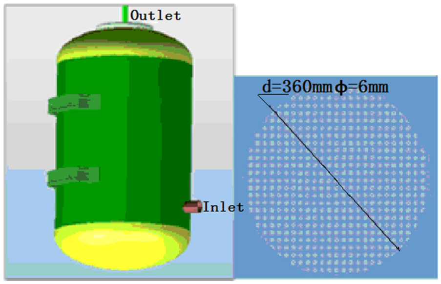
The system includes heat pump module and water route module, as shown in Figure 1. The heat pump module consists of a compressor, a condenser, an electric expansion valve, and an evaporator. The water route module contains an artesian and small buffer water tank, the functions of which are mainly to reduce the start-and-stop times of the compressor, to retard the transient fluctuation of the instant-heated system, and to enlarge the water flow rate. By changing steps of them, the stepping motors can adjust valve openings of valve 8 and valve 9, and then changing the water flow rates through the condenser and the water tank, respectively, thus manual controlling (on the experimental stage, there is currently no automatic control) of the total outlet water flow rate and temperature.

Diagram of IASHPWT.
The heating mode of water tank heating (WTH) is that the heat pump module is power-off. On one way, tap water goes into the inlet of the water tank (7), thus squeezing hot water out from the outlet, and the hot water goes through the motor water valve (8) into the water mixing device (10). On the other way, tap water goes through the water pump (5), the condenser (2) and the motor water valve (9) into the water mixing device (10). And finally, the water goes to users from the water mixing device.
The heating mode of condenser heating (CH) is that the heat pump module is power-on, meaning that the compressor (1), the fan of evaporator (4) and the electric expansion valve are power-on. Tap water goes through the water pump (5), gets heat from the condenser (2), then goes through the motor operated valve (9), the water mixing device (10), and finally to users.
The heating mode of condenser-water tank joint heating (CWTJH) is that the heat pump module is power-on, meaning that the compressor (1), the fan of evaporator (4) and the electric expansion valve work and the water tank works too. On one way, tap water goes into the inlet of the water tank (7), thus squeezing hot water out from the outlet, and the hot water goes through the motor water valve (8) into the water mixing device (10). On the other way, tap water goes through the water pump (5), the condenser (2) to get heat, and the motor water valve (9) to the water mixing device (10). And finally, the water goes to users from the water mixing device.
The followings are some illustrations of the system:
When consumed water flow of users is low, it can produce hot water directly either by WTH or by CH.
When the consumed water flow is high, it can supply hot water by CWTJH.
The volume of the buffer water tank is 60 L, comparatively small than that of the existing household HPWH, which is usually 120 L,150 L, or much bigger. The purpose of the water tank is that, on one hand, to provide hot water instantly without the heat pump module (the heating mode now is chosen as WTH) when the hot water consumption is low, thus decreasing the start-and-stop frequency of compressor. And on the other hand, to increase hot water production to meet the demand of users when the heating mode is chosen as CWTJH, such as when producing hot water of 6 L/min and 42°C at ambient temperature of −7°C.
The water flow mixing device is used to mix water from the buffer tank and the condenser. Moreover, it has an electric heater of 1.5 kW, and only when the ambient temperature is very low, for instance −7°C, the electric heater is open.
Test-rig and test conditions
Test-rig
According to the diagram of the system (as shown in Figure 1), the IASHPWT was constructed. Figure 2 shows an assembly drawing of the HPWH with a rated power of 2.0 kW, and R410A as working refrigerant. As mentioned above, the HPWH consists of a heat pump module and a water route module. The heat pump module is made up of a rotary compressor, a four-way reversing valve, a double-pipe condenser, an electronic expansion valve (EEV), and a finned tube evaporator. The water module is made up of a double-pipe heat exchanger, a water pump, two motor operated water valves, a water tank, and a mixing-flow device.

Equipment constitution of the system.
In the heat pump module, a rotary compressor was used and the total cylinder volume of the compressor is 16.0 cm3. The compressor frequency is controlled with a brushless DC motor driver. Figure 3 shows the compressor revolution range and the exhaust pressure. A finned tube heat exchanger with 3 rows, 52 steps, and 8 paths with inner and outer tube diameters of 7mm and 9.52 mm was used as the evaporator. The effective core dimension of the evaporator was 925mm, 1092mm and 38.1 mm. A counter flow heat exchanger was used as the condenser with outer tube diameter, inner tube diameter, thickness, length, and coil diameter of 15.88 mm, 9.52 mm, 1 mm, 13 m, and 0.14 m, respectively. In addition, an EEV, with inner diameter and resolution of 4 mm and 500 steps, was installed to control the condensing pressures in the refrigerant-water heat exchanger.

Revolution and exhaust pressure ranges of the compressor.
In the water route module, the cold tap water is heated by the refrigerant in the condenser and they are in counter flow type. The hot water (60 L volume) was fed into the top of the water tank to prevent convection heat transfer between the hot and cold water. What’s more, in order to prevent convection heat transfer between the hot water and the cold water, the buffer tank has two orifice plates of the same shape and size (as shown in Figure 4) and the locations of the orifice plates are 10 cm from the top and 10 cm from the bottom of the tank respectively.
Buffer water tank and its orifice plates.
The system was installed in a 3HP Enthalpy Lab and the test-rig was equipped with a water chiller to supply water of different temperatures, two turbine flowmeters to test the water flow rates, which were installed in the outlets of the condenser and the IASHPWT, respectively, and several faucets to simulate water consumed by users. Moreover, the control system of the IASHPWT contained a compressor frequency converter, a throttle regulator, a fan frequency inverter, two motor operated water valves, and the test system contains thermocouples, pressure sensors, a data acquisition unit, and so on. The measurement accuracies of the instruments are shown in Table 1.
Measurement accuracies of the instruments.

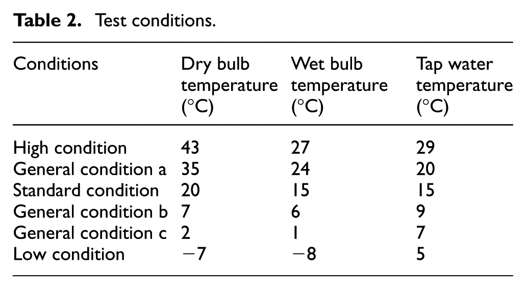
Test conditions
In accordance with Standard on Heat Pump Water Heater For Household And Similar Application of China, 14 the test conditions are shown in Table 2. In the experiments, the unit produced hot water directly from the condenser in the heat pump module when the ambient bulb temperatures were above 20°C (including 20°C), and the condenser and water tank joint supply hot water when the ambient bulb temperatures were under 20°C. The electric heater in the water tank would be open to heat the water to 80°C at ambient temperature of −7°C and only at this temperature was the electric heating pipe (1.5 kW) in the water mixing device open.
Test conditions.
Experiment results
Refrigerant charges
A proper refrigerant charge is good for the life of the equipment and can improve the heating capability. Then, according to the best COP, the best refrigerant charge is obtained.13–16 If the refrigerant charge is less, compressor suction temperature tends to be high and the exhaust temperature of the compressor tends to be high. In extreme condition, high temperature could trigger sudden shutdown of the unit and destroys certain components. If the refrigerant charge is too much, it is easy to trigger problems, such as refrigerant liquid stacking in the heat exchanger, pressures of evaporation and condensation rising, and power consumed by the compressor increasing. 12
As shown in Figure 5, the best refrigerant charge is 1.31 kg, and at this point, the heat COP is the highest and the heat capacity is around 11.0 kW. In variable frequency heat pump system, the best refrigerant charges are different in different frequencies, the best refrigerant charge is low while operating in a low frequency and high while operating in a high frequency. The best refrigerant charge refers to the value corresponding to the maximum of heat COP under conditions of a certain throttle and required heat capacity. In general, the range of refrigerant charges is achieved when the valid superheat of the evaporation outlet is 0°C, the valid overcooling in the outlet of the condenser is 10°C in standard ambient condition, and meanwhile the heat capacity is achieved. As a result, the best refrigerant charge of the system is 1.31 kg.

Heat capacities and heat COPs with refrigerant charges.
Compressor frequencies
Figure 6 shows the heat capacity and heat COP varying with the compressor frequencies in ambient temperature of −7°C when the throttle step and water flow in condenser are constant. When the compressor frequency increases, the heat capacity of the system increases. In condition of ambient temperature of −7°C, the heat capacity is 6.15 kW, and its corresponding frequency is 110 Hz. When compressor frequencies increase, the increase rate of heat capacities becomes slower and slower. Moreover, the curves indicate that there is a highest COP corresponding to a certain frequency, and the highest COP is 2.76 and its corresponding frequency is 100 Hz at the ambient temperature of −7°C. The heat COP and heat capacity variations relating to the compressor frequencies in various working conditions have the same trends as in working condition of ambient temperature of −7°C; the reason can be found in Koury et al. 15 and Segarra et al. 16

Heat capacity and heat COP with compressor frequencies.
Throttle steps
Figure 7 is the heat COP and heat capacity curves with the throttle steps in standard working condition (as shown in Table 2), and when the compressor frequency and water flow in the condenser are constant. When the throttle steps increase, the heat capacities first increase and then decrease. The peak is 10.1 kW, and its throttle step is 135. The reasons are as follows: first, the refrigerant mass flow increases along with the increase of the throttle steps; second, pressure drop of the throttle decreases with the increase of the throttle steps. The evaporating pressure and temperature increase, and the condensing pressure and temperature decrease; thus, the heat absorption from the evaporator and heat release from the condenser of per unit refrigerant mass flow decrease. The interaction of the two aspects leads the trend of heat capacity with the throttle steps, as shown in Figure 7. And in other working conditions, the heat capacity with the throttle steps has similar pattern with that in standard working condition.
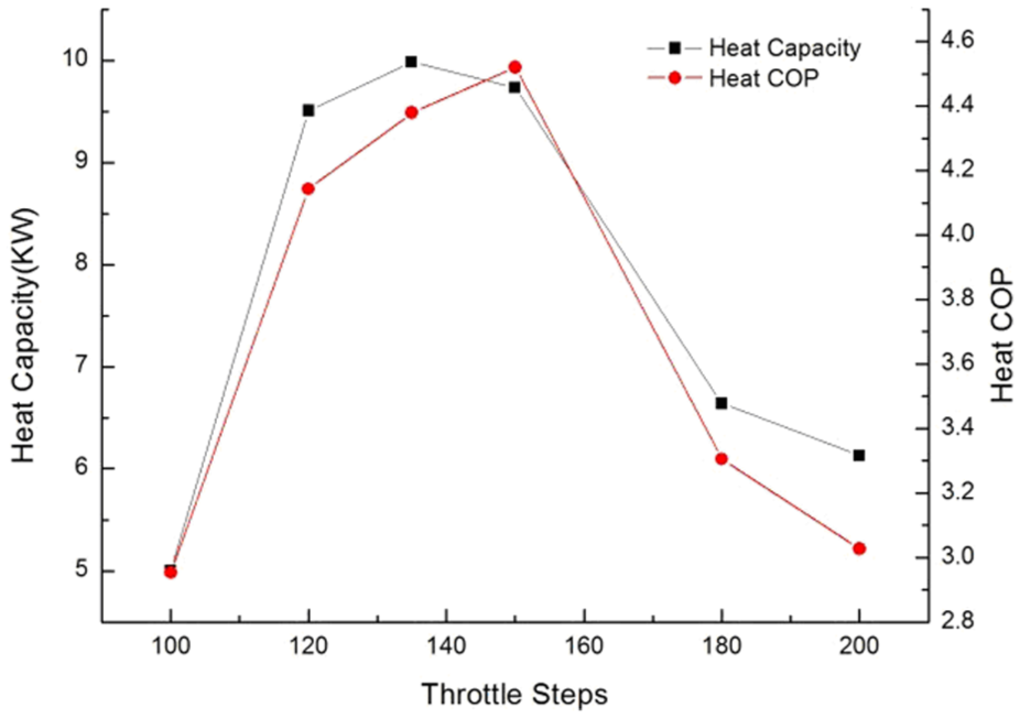
Heat capacity and heat COP with throttle steps.
As shown in Figure 7, the heat COP first increases and then decreases with the increase of the throttle steps and the highest heat COP is 4.5 and its corresponding throttle step is 150. This is because the consumed power of the compressor increases at first and then decreases, so does the heat capacity. The interaction of the two factors leads the trend of heat COP, as shown in Figure 7.
Thermal stratification of water tank
There was hot water of above 80°C in the buffer tank heated by an electric heater before experiments. When the water tank worked, the electric heater was off, and the tap water produced by the chiller flowed into the water tank from the inlet at the bottom of the tank, thus pressing hot water out from outlet on the top of the water tank. So there was a temperature drop of the outlet because of the mixing with the tap water. In order to decrease the temperature drop of outlet and make the system produce abundant hot water in low temperature environment, a partition with period structure was installed in the water tank.
Figure 8 shows the outlet water temperature curves, respectively of an ordinary water tank and the designed buffer tank, when the water temperature in both tanks was 86°C before experiments. And the experiments test begined when 1.2 L/min and 7°C tap water flowed into the water tanks. As shown in Figure 8, the times of the outlet water temperature above 60°C of ordinary water tank and the designed buffer water tank are 28.3 min and 10.5 min, respectively. Moreover, the outlet water temperature variation with time of the designed buffer tank is gentler and steadier than that of the ordinary tank overall. This is because the orifice plates in the buffer tank prevent convection heat transfer between the hot and cold water effectively. Compared with the common water tank, the designed buffer tank has a great improvement in the total water-supplying time. So there is a big advantage of the designed system, namely, the buffer water tank can operate independently or work with the heat pump module together to supply hot water to the user for a relatively long time.

Outlet water temperatures in different water tanks.
Water supply time
Moreover, the experiments studied the water supply time in variable conditions of the IASHPWT and the results are shown in Table 3. At the ambient temperature of 20°C, the heat pump module works and the water tank does not work, the outlet temperature can maintain above 42°C with a steady flow rate of 6 L/min. And, when ambient temperature is above 20°C, the heat pump module can supply hot water of a flow rate of 6 L/min at 42°C. At ambient temperature of −7°C, the heat pump condenser combines with the buffer tank to supply hot water of 6/min and 42°C. The 60 L buffer water tank can supply the same amount of water as a common electrical heating water tank of 155 L and the water supply time is 26 min due to the heat pump module. The results show that the unit can fulfill conventional household water needs and have application value.
Water supply time.

Discussions
Pressure comparison among instant heating, cyclic heating, and static heating
The discharge temperature and pressure of compressors in cyclic heating and static heating air-source HPWH with the water temperatures when the HPWHs are working, are shown in Figure 9. The temperature and the power consumed increase, while the heat capacity and the COP decrease. Under the condition of the same amount of water flow rate, the condensation pressure increases with the increasing ambient temperature. It is because that the heat capacity of the heat pump increases sharply when the ambient temperature increases. So the water temperature and the pressure in the condensation go up at the same amount of water flow rate. Thus, there is great need to study the performance of the system under high temperature conditions. Compared with the cyclic heating and the static heating, the suction pressure, the discharge pressure, and the heat COP are much steadier as shown in Figure 10 (the ambient temperature is 43°C, and the outlet water flow rate is 6 L/min at 42°C). It is because that the flow rate and temperature of the tap water entering the condenser keep almost constant, while they increase sharply in the cyclic heating and static heating, which cause the increase of the pressure and the decrease of the heat COP.

Log P-h of cyclic heating and static heating air-source heat pump water heater. 12

Suction and discharge pressures of IASHPWT.
Low temperature condition
The heat pump and the buffer water tank work together when the ambient temperature is −7°C. Figure 11 shows the temperature of the outlet water when the water flow rate is 6 L/min. To change the water flow rate ratio of the heat pump and the buffer tank, the steps of the motor operated valves are adjusted. As the figure shows, the temperature of the outlet water increases first and then reaches a steady state with a slight fluctuation of 1°C. It can last 33 min when the temperature of the outlet water is above 40°C with a steady water flow rate of 6 L/min. The temperature of the outlet water increases when heat pump operates and then reaches a steady state. But when the hot water in the buffer tank runs out, the temperature begins to decrease sharply and finally drops below 40°C.

Relationship between outlet water temperature and time.
Heat COP of heat pump module
In order to achieve 6 L/min and 42°C hot water and to test the performance of the IASHPWT, experiments were conducted in different conditions as shown in Table 2. At ambient temperature of −7°C, the water in the tank was heated to 80°C at the beginning, then the electric heater in the water tank was turned off, and electric heater in water mixing device was turned on. During the experiment, temperatures vary different at different locations of the water tank. It was very hard to consider the actual electric power consumed when calculating the COP of the whole IASHPWT. So the COP of the heat pump module is discussed here.
Figure 12 shows the heat COP curve of the heat pump module in different conditions as shown in Table 2. The heat COP of the heat pump module (or the IASHPWT, because the heating mode is chosen as CH) is 12.6 when the ambient temperature is 43°C. Reasons of this result are as follows: first, the inlet tap water is 29°C, so the heat capacity is less than other conditions; second, the suction exhaust pressure ratio is low, and the frequency of compressor is low too; third, the ambient temperature is high. The heat COP of the heat pump module (or the IASHPWT) at ambient temperature of 20°C is 4.5. The heat COP of the heat pump module at ambient temperature of −7°C is 2.76. The results indicate that the IASHPWT can work in ambient temperature from −7°C to 43°C, and according to China’s geographical and climatic factors, the IASHPWT system has certain application value in the area to the south of the Huaihe River to satisfy household hot water use.

Heat COP of the heat pump module in variable conditions.
Conclusion
An IASHPWT is proposed in this article, and the performance of the system under different conditions is tested. The results showed that the heat pump can produce 42°C and 6 L/min hot water with a heat COP of 4.5 at standard condition. And it can fulfill this goal of hot water production at severe conditions, such as at 43°C and −7°C, with the heat COPs of 12.6 and 2.76, respectively. It also indicated that the striking feature of the system is the condenser inlet water temperature and flow rate is constant in each condition; hence, the suction and exhaust pressure and temperature of the compressor are changeless, and as a result, the system can run steadily and safely. Moreover, the temperature stratification of the water tank is obvious and the water tank can associate with the condenser to supply hot water, thus increasing hot water supplied time. The innovation in this article is the design of the buffer tank, which helps to fulfill the designed goal of the whole unit. The instantaneous-heating air source heat pump water heater has great application prospect, especially that it may be used in the family to replace the existing electrical heating water heater or the gas water heater.
Footnotes
Academic Editor: Yangmin Li
Declaration of conflicting interests
The author(s) declared no potential conflicts of interest with respect to the research, authorship, and/or publication of this article.
Funding
The author(s) disclosed receipt of the following financial support for the research, authorship, and/or publication of this article: The authors received financial support for the research from Haier Group, Qingdao, China.