
Abstract
The main factor determining the performance of a thermal storage method is the temperature stratification in the storage tank. At the ideal stratification, the energy efficiency of the storage tank is extremely high. However, when the heat pump is applied, the stratification is disrupted by heat exchange between the layers of the heat medium, and consequent convection in the tank. Therefore, this study analyzed the influence of stratification-related design factors in the water-piping facility area outside a tank heated by a heat pump. In particular, it assessed the thermal stratification and energy efficiency in the storage tank installed with a mixing valve. In the system using the mixing valve, hot water of constant temperature was supplied to the top of the storage tank, reducing the mixing effect of the hot and cold waters; consequently, the stratification index was maximized at 0.42. Comparing the times at which the temperature of the uppermost part reached 70°C in the systems with and without the mixing valve (30 and 75 min, respectively), we find that the mixing valve reduced the time of obtaining effectively hot water by approximately 60%.
Keywords
Introduction
Under national policies on greenhouse gas emissions reduction, most facilities in the energy industry are being replaced by eco-friendly and high-efficiency products. In addition, to improve the power efficiency, thermal storage systems are now widely used in commercial and residential hot-water and floor-heating systems. 1 Water-based thermal storage using sensible heat is cheaper than other thermal storage methods, uses easily available water as the heat medium, and has a simple facility configuration. Heating and hot-water loads vary greatly among building types and occupants, and the peak load largely differs from the average load. When an energy system that produces hot water is designed to take the maximum load, excessive equipment is required. A thermal storage tank can reduce the capacity of the plant by suppressing the peak load, which can drastically reduce the facility investment cost. Water-based thermal storage systems using sensible heat can be heated by two sources: conventional electric heaters or heat pumps. Figures 1 and 2 show a thermal storage tank installed with an electric heater and a heat pump, respectively. The conventional heater heats the water in the tank with an electric coil, whereas the heat pump uses the heat generated from its own condenser. The heat pump uses considerably less energy than the conventional electric heater.
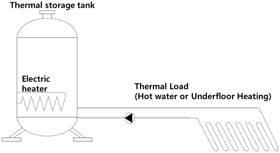
Thermal storage system heated by an electric heater.

Thermal storage system heated by an air-cooled heat pump system.
Temperature stratification majorly determines the performance of a water-based thermal storage system.2,3 The peak-load reduction effect of the storage tank can be further increased by precisely controlling the temperature stratification in the storage tank. The ideal stratification maximizes the energy efficiency of a heat storage tank.4,5 The stratification inside the storage tank largely depends on the diffuser shape, the tank shape, and the flow velocity. Fluid mixing at the inlet is the major cause of stratification failure, and various studies have investigated the relationship between stratification level and diffuser shape.6–10 In general, stratification is most effective in thermal storage tanks with higher aspect ratio, but there are limitations on installation places and transportation. The stratification characteristics in thermal storage tanks with different aspect ratios have been studied in experiments and analyses.11,12 Stratification is greatly influenced by the inlet shape and flow rate of the thermal storage tank.13–15 Most of the research on stratification in storage tanks has focused on spatial dimensions such as diameters and heights, and on the internal distributions in storage tanks using diffusers. Many studies have been conducted on the heat transfer enhancement of heat exchanger, a component that greatly affects the efficiency of heat pump boilers. Nanofluid technology was mainly used to improve heat transfer, and the results of improved thermal performance in various types of heat exchangers were shown.16–19
In addition, heat pipes are used for effective heat exchange in a low temperature region. 20 In order to improve the efficiency of the refrigeration cycle, vapor injection technology using economizer and technology using various refrigerants are applied. 21 In the present study, we analyze the effect of stratification-related design factors in the external water pipe area rather than the tank interior. In particular, we compare the temperature stratification distributions and energy efficiencies in the storage tank with and without a mixing valve. With the mixing valve installed in the water pipe area, we also changed the temperature and flow rate of the hot water introduced to the storage tank, and analyzed the temperature stratification distribution in the storage tank.
In the present study, we analyze the effect of stratification-related design factors in the external water pipe area rather than the tank interior. In particular, we compare the temperature stratification distributions and energy efficiencies in the storage tank with and without a mixing valve. With the mixing valve installed in the water pipe area, we also changed the temperature and flow rate of the hot water introduced to the storage tank, and analyzed the temperature stratification distribution in the storage tank.
Experimental investigation
Experimental setup
The water-based thermal storage and heat pump unit consists of an outdoor unit, an indoor unit, a storage tank, and a water pipe including a pump (see Figure 3). In the whole system, the pipe is divided into a refrigerant pipe and a water pipe. The heat exchanger, which acts as the evaporator in the heat pump, is located outdoors, and the piping and fittings are located indoors. The low-temperature water discharged from the bottom of the storage tank circulates through the condenser to the top of the storage tank, where it receives heat from a high-temperature refrigerant in the condenser of the heat pump system. Figure 4 shows the installation of a mixing valve with three piping connections.

Configuration of the heat pump and thermal storage tank system.

Schematic of heat flows in a heat pump system with a mixing valve.
The valve is connected to the outlet and inlet sides of the heat pump, and to the storage tank side. It then controls the temperature of the water passing through the condenser. Under the mixing-valve control, the water temperature at the boundary of the thermal storage tank is maintained at a gradient from bottom to top. When the user requires hot water, the water is extracted from the top of the storage tank, which is considerably more energy-saving than heating the water throughout the tank.
Heat pump system
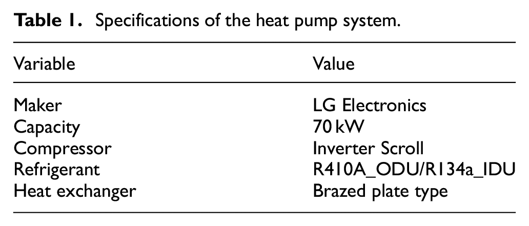
The heat pump system for hot water generation comprises an outdoor unit and an indoor unit. The outdoor unit serves as an evaporator. Heated by the outside air, the refrigerant in the outdoor unit is vaporized and moves to the compressor. The outdoor unit connects to the indoor unit through refrigerant pipes. Within the indoor unit, a plate-type heat exchanger ensures that the refrigerant and water are circulated in the refrigerant pipe and the water pipe, respectively. The present experiments were performed on an air-cooled heat pump system with a 70 kW capacity. The system specifications are listed in Table 1. Unlike a gas- or oil-based heat source system, a heat pump system raises the water temperature stepwise, maintaining a constant difference between the inlet and outlet temperatures.
Specifications of the heat pump system.
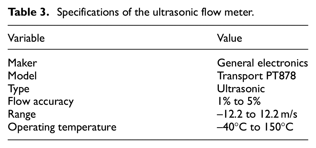
The water entering the indoor unit of the heat pump system is then heated by the designed temperature difference. This heating strategy characterizes the inverter compressor operation method. Here, the indoor unit was designed to maintain an inlet–outlet temperature difference of 7–10°C, and the circulation between the thermal storage tank and the indoor unit was maintained by a centrifugal pump (PH-350M, Wilo, Korea). We measured the flow rate supplied to the heat pump through an ultrasonic flow meter (Transport PT878, General Electronics, USA).
Mixing valve
The three-way mixing valve consists of a valve body and a valve operator, as shown in Figure 5. The valve body consists of two inlet ports and one outlet port. To generate the target temperature (TAB), the actuator assesses the values of the temperature sensors built into the A and B ports, and adjusts the opening of the valve. The circulating water then exits the AB port at a constant temperature. The mixing valve specifications are given in Table 2.

Components of the mixing valve. The flows through ports A and B are mixed in port AB.
Specifications of the three-way mixing valve.

The final temperature of mixed fluids with different water temperatures and flow rates is determined by the first law of thermodynamics, and is computed by equation (1).

where TA, TB, and TAB are the water temperatures of ports A, B, and AB, respectively, and QA and QB are the flow rates of the water in ports A and B, respectively.
Experimental method
In this study, the mixing valve adjusted the flow rate and temperature of the inlet water entering the thermal storage tank. For convenience, a bypass pipe was installed around the mixing valve.
The stratification in the thermal storage tank was analyzed in the presence and absence of the mixing valve on the load side.
When the mixing valve was installed, the temperature of the mixed and discharged water was fixed at 75°C, and the temperature of the water entering the heat pump was maintained at 68°C. These temperatures were controlled by a proportional control actuator, which automatically adjusted the opening ratio of the mixing valve according to the water temperature.
Experiments were performed in a typical heat pump system in the absence and presence of a mixing valve. Each experiment was conducted under the same conditions (0°C, 60% relative humidity) and was completed in the same time (∼90 min on average). The initial and target temperatures of the thermal storage tank were 35°C and 80°C, respectively. The flow rate was measured using an ultrasonic flow meter, and the specifications of the flow meter are described in Table 3 and the attached picture is shown in Figure 6. The water flow rate was 73 LPM in each case.
Specifications of the ultrasonic flow meter.
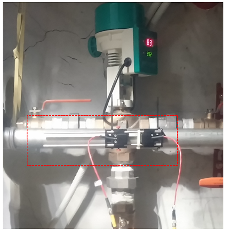
Ultrasonic flow meter.
Experimental equipment specifications
The thermal storage tank (capacity = 1800 L) is shown in Figure 7.

Drilling positions for measuring the internal temperature of the thermal storage tank.
The vertical temperature distribution was measured by eight temperature sensors installed at 200-mm intervals from the bottom to the top of the tank. From the temperature distribution, we obtained the stratification in the storage tank. As shown in Figure 4, the temperature measurement points in the system are two inlet and outlet of the heat pump, the outlet of the three-way valve, and eight locations for each height of the storage tank. The temperature sensor used a K type thermocouple, and measured in real time using a data logger(Hilogger 8430-20, Hioki, Nagano, Japan) and a PC.
Results
Heat pump inlet and outlet temperature measurements
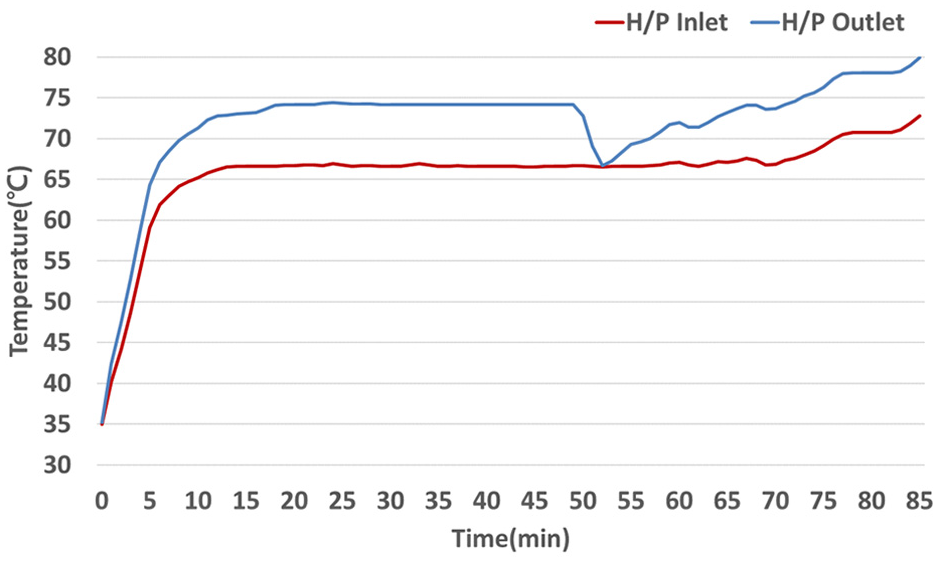
Figure 8 compares the water temperatures before and after passing the condenser in the system without a mixing valve. The temperatures were measured in real time by K-type temperature sensors installed in the inlet and outlet pipes of the indoor unit of the heat pump. The capacity of the heat pump system was 70 kW, and the theoretical temperature difference between inlet and outlet (based on the circulation flow rate of 73 LPM) was 7°C. The outlet temperature was approximately 7°C higher than the inlet water temperature. After 18–21 min of operation, the outlet temperature was reduced by the defrosting operation.

Temperatures at the inlet and outlet of a normally installed heat pump.
Figure 9 compares the water temperatures before and after passing the condenser in the system with a mixing valve. The mixing valve proportionally controlled the opening degree of the valve to maintain the set temperature, thereby maintaining a constant temperature at the condenser inlet and outlet of the heat pump system. At the beginning of the operation, the flow was controlled by a three-way valve until the temperature reached the set temperature. Thereafter, the operation was performed at the rated flowrate.
Temperatures at the inlet and outlet of a heat pump installed with a mixing valve.
During the first 15 min, the water temperature rose rapidly to the set temperature under the three-way valve control. Thereafter, the inlet and outlet temperatures remained constant except when the outlet temperature was decreased by defrosting after 50–53 min of operation.
Water temperature distribution over the storage tank height
Figure 10 shows the temperature distribution along the vertical height of the storage tank in the system without a mixing valve. At the start of the test, the average water temperature inside the tank was 35°C. The test was continued until the water temperature reached 80°C.
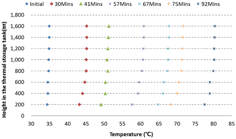
Height temperature distributions inside the thermal storage tank without the mixing valve, measured at various times.
As time progressed, the average temperature of the water rose, but remained approximately constant along the height dimension, with no large deviations. Clearly, the stratification was destroyed by the forced convection from the pump, which mixed the water layers. The heating time to 70°C was 75 min.
Figure 11 shows the temperature distribution along the vertical height of the tank with the mixing valve. As observed in the system without the mixing valve, the test temperature of the water in the storage tank was originally 35°C and eventually reached 80°C. The circulating flow rate and initial tank temperature were those of the system without the mixing valve, and the mixing-valve inlet temperature was 65°C. The temperature of the circulating water entering the storage tank was constant. That is, when part of the water discharged from the heat pump flowed into one port of the valve under proportional control, the cold water discharged from the tank flowed into the port opposite the mixing valve, and was mixed. This mechanism ensured a constant temperature of the water flowing into the heat pump, and a constant temperature of the water discharged from the heat pump. Therefore, the temperature of the water flowing into the tank was also constant. As mentioned above, the mixing valve controls the water-supply temperature by adjusting the opening ratio of the actuator. The inlet and outlet temperatures were determined by sensors installed in the valve port.

Height temperature distributions inside the thermal storage tank with the mixing valve, measured at various times.
After approximately 11 min, the three-way valve was opened and water at 65°C began flowing into the storage tank from the indoor unit of the heat pump. After 13 min, a temperature change was detected by the top sensor of the tank. After 18 min, the temperature of the uppermost sensor (T8, at height = 1600 mm) was 55.6°C and 20°C higher than the initial water temperature in the thermal storage tank. In addition, the water temperature at the top of the tank reached 70°C after ∼15 min of operation, approximately 40 min faster than in the system without the mixing valve.
Thermal stratification in thermal storage tanks has been evaluated by various methods, including graphical methods, the thermal stratification index, the energy approach based on the laws of thermodynamics, the exergy approach, the thermocline gradient method, and combinations of methods.22–27
In this study, the degree of stratification was quantified by the stratification coefficient ST and stratification index RTS, given by equations (2) and (3), respectively. Both measures are obtained by the mean-square deviation method. 28 In equations (2) and (3), mstore is the mass of the medium in the tank, n is the number of intervals delineating the horizontal layers, and i is the i-th horizontal layer in the tank. Ti is the temperature of the i-th horizontal layer, and Tavg is the mass-weighted average temperature of the thermal energy in the tank. In equation (3), STt and STf denote the stratification coefficients after time t and in the fully stratified state, respectively. When the stratification index RTS is 1.0 and 0.0, the system temperature is completely stratified and completely mixed, respectively.


At 13 min after the start of the test, the RTS was close to zero in both systems. As shown in Figure 12, the RTS of the system with the mixing valve began changing rapidly at 18 min into the test. The RTS of the system with the mixing valve was maximized at 0.42 after approximately 42 min, then gradually decreased. After approximately 78 min, the stratification ratio was nearly zero and the temperature layers were totally mixed. The RTS reduced later because the experiment was not conducted under a load that maintained the same test conditions. Eventually, the continuous supply of heat homogenized the temperature inside the storage tank. Under actual loaded conditions, stratification is expected to be maintained over a long time.

Comparison of RTS values in the systems with and without the mixing valve.
Coefficient of performance of the heat pump
Next, the coefficient of performance (COP) was measured in both systems. The water temperature of the thermal storage tank was 35°C at the start of the experiment, and 80°C (on average) when the experiment finished. The target temperature was reached at 80 and 85 min in the systems without and with the mixing valve, respectively. The heating capacity was calculated by equation (4) using T type thermocouples and an ultrasonic flow meter to measure temperature difference of inlet and outlet of heating water and water flow rate. The heat pump’s power consumption was measured by an electricity power meter. As equation (5) indicates, COP of the heat pump is obtained by dividing the heating capacity by power consumption. 29


Over the entire runtime, the COPs were 2.39 and 2.28 in the systems without and with the mixing valve, respectively (see Figure 13). Excluding the defrosting, they were 2.37(excluding 18 to 21 min) and 2.33(Excluding 50 to 53 min), respectively. In the system with the mixing valve, the COP was low in the initial section because high-temperature water (65°C) flowed into the heat pump, and a high-pressure cycle was formed from the beginning of the operation, providing a control load for raising the temperature. The overall COP was also slightly lower than in the system without the mixing valve. When the mixing valve was absent, the inlet and outlet water temperatures were relatively low in the initial sections, so the condenser of the heat pump could operate under relatively low pressure, raising the COP in this system.
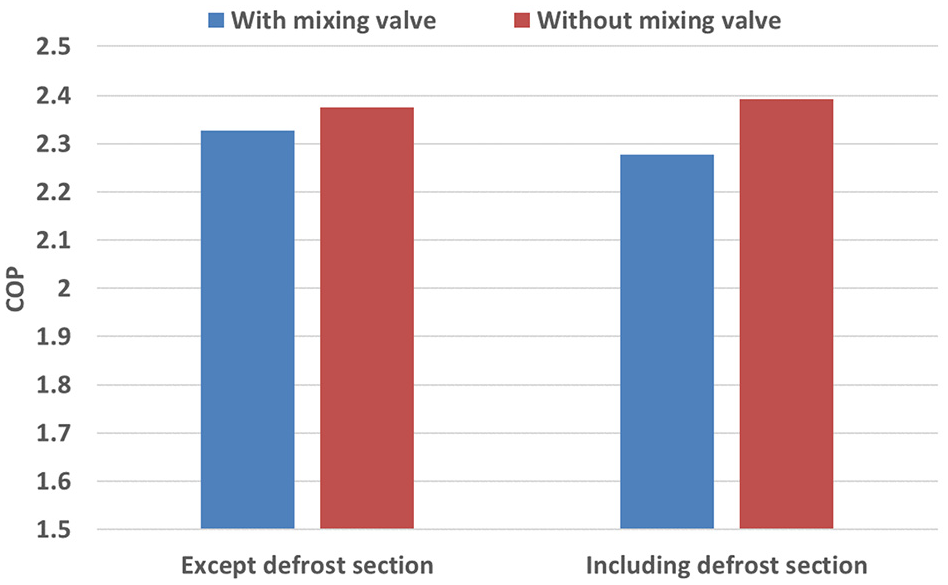
Comparison of coefficient of performances in the systems with and without the mixing valve.
Conclusion
This study experimentally investigated the temperature stratification in a thermal storage tank installed with a mixing valve in the circulating water-piping area. The design elements inside the heat pump system and thermal storage tank were not considered, as they have been extensively investigated in previous works.
The mixing valve was found to greatly raise the stratification ratio, meaning that the effective energy was increased, and that short-term operation of the equipment could effectively cope with the partial load.
The other main conclusions are summarized below.
When constant-temperature hot water was supplied to the top of the storage tank, the mixing valve reduced the mixing effect of the hot water with the cold tank water, maintaining the temperature stratification in the tank. For stratification, the temperature of the supplied hot water must be equal to or higher than the temperature of the water stored in the tank.
The mixing valve reduced the flow rate into the thermal storage tank because the bypass flow rate maintained the outlet temperature. This configuration helps to maintain the stratification by reducing the mixing effect of the hot and cold waters.
As the heat pump operation proceeded, the temperature boundary layer in the tank gradually moved downward toward the bottom of the tank. The mixing valve delivered excellent stratification performance, but required a longer time and higher energy consumption to reach the average temperature and the target temperature of the thermal storage tank.
In the tests with mixing valves, the heat pump operated under high-pressure conditions over most of the operating time. Such high-pressure operation can be disadvantageous in terms of energy consumption, but enables the quick provision of hot water (≥70°C). Comparing the times at which the temperature of the uppermost part reached 70°C in the systems with and without the mixing valve (30 and 75 min, respectively), we find that the mixing valve reduced the time of obtaining effectively hot water by approximately 60%.
In further research and performance reviews, the control logic of the heat pump must be improved to benefit not only the thermal storage stratification, but also the energy consumption.
Footnotes
Appendix
Handling Editor: James Baldwin
Declaration of conflicting interests
The author(s) declared no potential conflicts of interest with respect to the research, authorship, and/or publication of this article.
Funding
The author(s) disclosed receipt of the following financial support for the research, authorship, and/or publication of this article: This study was financially provided by the National Research Foundation of Korea(NRF) grant and the Korea government(MSIT) (No. 2018R1A2B6004137)