
Abstract
An experiment was carried out on a domestic condensing heat recovery air-conditioner. The working principle was introduced in this article. And thermal performance and theoretical analysis of the dynamic behavior of the system were conducted followed by experimental investigation. The results illustrated that the operating parameters of various modes were satisfactory. In the summer and winter seasons, the space cooling performance (COPsc) and space heating performance (COPsh) values were 2.85 and 3.37, respectively. In the condensing heat recovery for water heating mode, the average COPwh was found to be 2.58, and the COPsc was observed to be 2.84 with an overall coefficient of performance (COPcw) of up to 5.42; the mean heat recovery rate was about 95%. In water heating only mode, the heat capacity was declining with an average COPwh value of 3.94.
Keywords
Introduction
Air-conditioners have become family necessities in most countries. Although the indoor environment is improved when the air-conditioner is in use, the operation is accompanied by a waste of the condensing heat. The amount of such energy wastage is not only significant worldwide but also leads to thermal pollution. Furthermore, the need for hot water in households consumes a large amount of other forms of energy (electricity and gas), thus aggregating pollution. An innovative concept or technology that could substantially reduce the costs for space cooling and water heating would thus be highly regarded. Such a technology would not only generate considerable economic benefits but also involve environmental advantages.
The notion and experiments concerning air-conditioner waste heat recovery for water heating were initially proposed in the 1060s. 1 The hot water generated can be utilized to meet the daily necessities of a domestic household, such as the hot water required for baths and washbasin and that used in kitchen and washing machines. Since then, the condensing heat recovery air-conditioner, as an energy-saving device, has received considerable attention and experienced rapid development due to its desirable energy conservation effect. For instance, D’Valentine and Goldschmidt 2 and Lee and Jones 3 established models based on mathematical reflection to assess the overall system optimization of a heat recovery air-conditioner system. Ying 4 in Singapore and Lee and Jones 5 in the United States carried out an investigation on a heat recovery air-conditioner system integrated with a Canopus heat exchanger as a desuperheater. Bong et al., 6 Toh and Chan, 7 and Abu-Mulaweh 8 compared the performances of various types of heat exchangers used for heat recovery. Su et al. 9 constructed a thermodynamic model for an irreversible Carnot refrigerator with heat recovery (CRHR) to optimize heat transfer area allocation. In addition, the exergy efficiency optimization based on the mathematical model was studied. Monerasinghe et al. 10 in Malaysia, Ying 4 in Singapore, and Techarungpaisan et al. 11 in Thailand presented a storage-enhanced heat recovery room air-conditioner (SEHRAC) in which a water storage tank with a tank-immersed refrigerant-to-water heat exchanger for heat recovery was utilized to meet the water needs in residential units with a high occupancy density. Jia and Lee 12 in Hong Kong further compared the performance of a capillary tube (CT) and thermal expansion valve (TEV) on the performance of a SEHRAC under various outdoor temperature condition. The experimental results indicated that the TEV was more suitable for use in the off-design condition. Compared to the CT system, the space cooling and water heating capacities improved by 16.3%–19.4% and 18.5%–23.4%, respectively, and the total coefficient of performance (COP) improved from 12.5% to 20.9%. D’Valentine and Goldschmidt 13 also performed a pilot study on the performance of the SEHRAC’s under conditions of various ambient and inlet water temperatures. Jiang et al. 14 also conducted a similar investigation in China. Baek et al. 15 investigated a SEHRAC using CO2 as the working medium. The results showed that the hot water temperature achieved could be more than nearly 65°C. Gong and colleagues16,17 carried out an experimental study on a novel multi-functional heat recovery air-conditioning system and constructed a dynamic simulation model to assess the potential energy-saving and fuel cost savings for a typical hotel in South China. The results showed that the system had a large COP and was especially suitable for hotel buildings. Jiang et al. 18 presented a modified air-conditioner with a domestic hot water supply (ACDHWS) and incorporated a control scheme for the electronic expansion valve; further, they performed an experimental study on the dynamic behavior and performance of the system. The results illustrated that the system could operate all-year round and that the average COP was improved despite a decrease in the cooling capacity at the initial condensing heat recovery stage. Olszewski 19 carried out an economic analysis on the viability of air-conditioners for hot water supply in 28 cities in the United States. In Hong Kong, Chen and Lee 20 and Jia and Lee 21 also performed an energy analysis on the energy conservation effect of heat recovery air-conditioner system. The results revealed that the thermal efficiency reached 50%. Ji et al. 22 and Dong et al. 23 in China developed a multi-functional domestic air-conditioner with a heat recovery function, respectively. The proposed novel system could operate stably and flexibly under various conditions. All the aforementioned condensing heat recovery air-conditioners demonstrated excellent energy saving. However, a simple, easy-to-control, reliable multi-functional air-conditioner that is suitable for ordinary families is still rare, and the thermodynamic operation characteristics of such a system have not been studied extensively.
This article proposes a novel schematic diagram of a domestic condensing heat recovery air-conditioner (DCHRAC). The DCHRAC is developed from the aforementioned SEHRAC, by replacing the extra tank-immersed refrigerant-to-water heat exchanger with a double-pipe heat recovery exchanger in which the water is heated to the desired temperature and then stored in a separate water tank. Compared to the SEHRAC with only two functions of space cooling and condensing heat recovery, the DCHRAC can perform more functions and is suitable for areas in which space heating is also required. Compared with other multi-functional air-conditioners mentioned above, the DCHRAC has a simple structure and low production and maintenance cost. This current study intends to test and evaluate the thermal performance of this system in each mode, specifically in terms of dynamic parameter variations in the heat recovery mode. Based on the experimental results, a theoretical analysis is presented as well, which is expected to facilitate the development of a reliable DCHRAC product.
Design of the DCHRAC units
Description of the units
A general schematic diagram of a DCHRAC is illustrated in Figure 1. It was designed for four operating modes (that are, a space cooling mode, a space heating mode, a condensing heat recovery for water heating mode, and an air-source water heating mode). The DCHRAC, in which a double-pipe heat recovery exchanger was used, is of simple structure and can be installed easily. It is primarily suitable for subtropical and temperate regions in which space cooling, heating, and domestic hot water are all essential requirements. The specific functions of the proposed air-conditioner are as follows.

Schematic diagram and photograph of the experimental system: (a) schematic diagram and (b) photograph of the experimental system.
Space cooling mode
The refrigerant flow in this mode is indicated by the solid arrows as shown in Figure 1(a). The fan of the air-cooled condenser is on; no water flow occurs via the condensing heat recovery exchanger. The DCHRAC behaves like a conventional air-conditioner.
Condensing heat recovery for water heating mode
The refrigerant flow direction when both hot water and space cooling are simultaneously required is also shown by the solid arrows. The fan of the condenser is off; water flows into the heat recovery exchanger where it is heated by the high-pressure and high-temperature refrigerant vapors discharged from the compressor. Next, the refrigerant is further cooled in the air-cooled condenser.
Air-source water heating mode in transitional seasons
If only hot water is required, the air-conditioner works as an air-source heat pump water heater. In this mode, circulation may be similar to that in the condensing heat recovery for water heating mode. The solid arrows represent the refrigerant flow. The condenser fan is turned off and the water is heated in the heat recovery exchanger. The test was carried on until the hot water temperature in the tank reached 55°C.
Space heating mode
In winter, when the temperature decreases, the four-way reversing valve switches on to reverse the refrigerant flow direction represented by the hollow arrows; there is no water in the condensing heat exchanger. The outdoor air-cooled unit operates as an evaporator, while the indoor heat exchanger works as the condenser for space heating.
In winter, when the DCHRAC is used to supply hot water, it will have adverse effects on the indoor environment for structural reasons. Therefore, the experimental study of hot water in winter was not carried out in this study. If hot water is desired at this time, other types of water heaters can be considered instead.
It is noteworthy that there is no bypass for the air-cooled condenser or the heat recovery heat exchanger, because when the devices are used as a redundant attachment, the refrigerant flowing through them is in a single-phase flow state and its sensible heat loss is relatively small. This phenomenon is introduced later in this article.
Design of the units
The experimental units are mainly composed of a heat recovery air-conditioner as well as a water tank. The detailed specifications of the units are presented in Table 1.
The heat recovery air-conditioner with a rated cooling capacity of 3.4 kW mainly includes the following primary components: a hermetic and rotary compressor (2K22C225, Panasonic, Guangzhou, China) is used to compress the refrigerant into high-temperature and high-pressure vapor; an air-cooled condenser with a total length of 29.16 m is used to discharge the waste heat of the air-conditioner; a fined tube evaporator with a total length of 14.4 m is used to lower the indoor air temperature; a double-pipe heat recovery exchanger, insulated from ambient air using black waterproof rubber thermal board with a thickness of 10 mm, is used to recover the waste heat of the air-conditioner for water heating; two capillary tubes having a diameter and length of 1.4 mm in diameter and 560 mm in length are used to regulate the amount of the refrigerant; the amount of the refrigerant (R22) was determined according to actual needs.
A pressure-bearing water tank with a volume of 150 L and a maximum working pressure of 0.6 MPa was designed to meet the daily hot water requirements of a typical family, 4 and the tank was insulated from the ambient air using a 50 mm thickness polystyrene foamed plastic with a stainless steel plate. Its purpose was to store the hot water heated cyclically by the heat recovery exchanger.
Specifications of the main components of the system.

ID: inner diameter; OD: outer diameter.
Experimental measurements
The experimental investigation of each function of the air-conditioner was conducted in an enthalpy laboratory conforming to Chinese standard (GBT7758-2010) located in Guangzhou, China. The enthalpy laboratory was composed of three distinct parts: two environmental chambers and a controlling room. The two adjacent environmental chambers pertaining to the indoor and outdoor environments were separated by a heat shield. The outdoor chamber was utilized to simulate the outdoor operating environment of the air-conditioner with pre-set temperature and humidity conditions. The function of the indoor chamber was to simulate the various space cooling and heating situations. In the two environmental chambers, the air temperature and relative humidity were controlled to the desired values. The thermal environments of the performance tests of space heating, space cooling, and water heating are described in Table 2.
Testing environment of the DCHRAC.

DCHRAC: domestic condensing heat recovery air-conditioner; DB: dry bulb; WB: wet bulb.
The data acquisition system consisted of a Keithley data acquisition instrument, temperature sensors, thermometers, and pressure meters. The test instruments are described in Table 3.
Summary of primary measurement instruments.

F.S.: full scall; RH: relative humidity.
Changes in the refrigerant temperature were quantified by T-type thermocouples: two were fitted on the copper’s surface at the compressor’s inlet/outlet, two were installed at before and after the capillary, and one was placed at after heat recovery exchanger. All the thermocouples were covered by a thermal isolation plate to ascertain a close connection between the thermocouples and the tube. The humidity and temperature of the inlet/outlet of the evaporator were quantified by Rotronic (HygroFlex), which was placed in two locations for the dry bulb air temperatures and two locations for the wet bulb air temperatures, before and after the evaporator. The outdoor dry bulb and wet bulb temperatures, similar to the condenser inlet air temperature, were quantified by two thermometers. The water temperature variations were quantified using the Pt100 RTD (Omega), which was installed to measure the water temperatures at four different positions within the water tank, and the average value of these four positions was taken as the water temperature. Two of these were installed at the inlet and outlet of the heat recovery exchanger to measure the variations in the hot water temperature. Measurements were collected continuously in 5°C intervals throughout the entire test until the water temperature reached 55°C. Subsequently, the data were transmitted to a computer.
The refrigerant pressures were measured using Bourdon pressure gauges placed at the compressor’s inlet and outlet. The two Bourdon pressure gauges, with various measurement ranges, were adopted to improve the measurement accuracy.
The system’s instantaneous and overall power consumption were recorded using a FLUKE 39 power meter with a measurement range of 0–10 kW (±2%). A desk computer in the control room was used to monitor and collect experimental data during the complete process.
Analysis of the system
Simple mathematical models were applied to analyze the operating behavior and efficiency of the recovery air-conditioner. During the experiments, the space cooling capacity (Qsc) and heating capacity (Qsh) were determined via the air supply quantity as well as the air enthalpy variation before and after the evaporator and condenser


where m represents the air mass flow rate, kg/s; hiev and hoev represent the air enthalpy before and after the evaporator, respectively, kJ/kg; hicon and hocon are the air enthalpies before and after the condenser, respectively, kJ/kg; tair represents the air temperature, °C; d represents the moisture content of the air, kg/kg; φ represents the air relative humidity; Pws represents the saturated pressure of moisture vapor, Pa; P0 represents the atmospheric pressure, Pa; A1–A6 represent the regression coefficients illustrated in ASHRAE Handbook 24 ; and Tair represents the air absolute temperature, K.
The coefficient of performance for space cooling (COPsc) and the coefficient of performance for heating (COPsh) can be described as
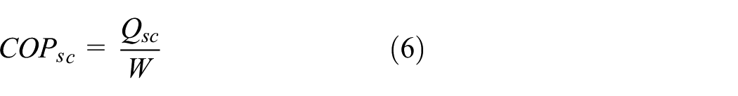

where W represents the system’s power consumption, kW.
The water heating capacity (Qwh) can be defined as

where ρ represents the water density (ρ = 1000 kg/m3); cp represents the specific heat of hot water at constant pressure (cp = 4.186 kJ/(kg K)); V represents the volume of the water tank (V = 0.15 m3);
tw 1, tw2 represents the mean temperature of the water before and after heating in the tank at a unit time interval, °C; and Δt represents the time interval, h.
The coefficient of performance for water heating (COPwh) is calculated using

The overall coefficient of performance (COPcw), which takes into account Qsc, Qwh, can be expressed as

Experimental procedures
Before the experiment commenced, all the measurements were initiated to ensure that all the instruments were ready. Once the experiment started, all desired parameters were recorded as required.
In both space heating and space cooling modes, the experiments were carried out under the conditions specified in Table 2 until a steady state of the operating characters of the DCHRAC was obtained. In the heat recovery mode, the actual water flow rate was 0.75 m3/h, and the water tank volume was 150 L, corresponding to a typical family’s daily consumption for bathing. The water in the tank was pre-heated to 20°C (which is the average tap water temperature in hot weather season in China). Furthermore, the experiment was carried out instantly under the conditions listed in Table 2.
In the water heating only mode, the water in the tank was pre-heated to 15°C (average tap water temperature during the transitional season in China). The outdoor chamber temperature was adjusted to the corresponding condition presented in Table 2. The experiment was carried out when the water in the tank was heated gradually to an average temperature of 55°C with a water flow rate of 0.7 m3/h. All the data were recorded at hot water temperature intervals of approximately 5°C.
Results and analysis
Here, the dynamic behavior and the thermal performance of the experimental equipment are presented. The specific results are as follows.
Space cooling performance
It is noted that both the discharge pressure (Pd) and suction pressure (Ps) of the system were maintained within the normal range, as illustrated in Table 4; the same behavior was noted for the discharge temperature (t d TS) and the suction temperatures (ts). The value of Qsc is 3409.25 W, which is nearly equivalent to the rated power of 3400 W; the COPsc is 2.85, which is slightly larger than the expected value of 2.84.
Performance data for space cooling.
Space heating performance
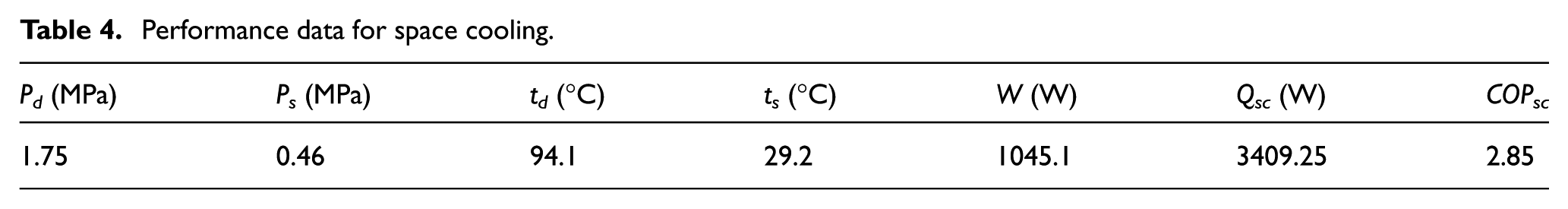
It can be seen from Table 5 that Pd and Ps, as well as td and ts, are considered to be within the normal range. The Qsh is 3564.45 W, and that of COPsh value is 3.37.
Performance data for space heating.
Condensing heat recovery for water heating performance
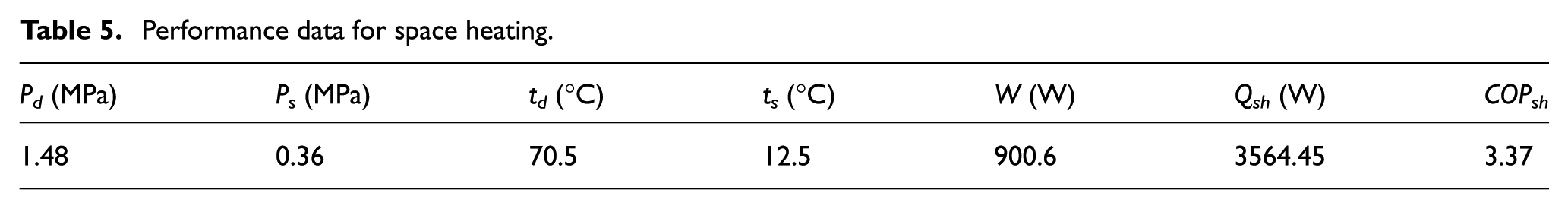
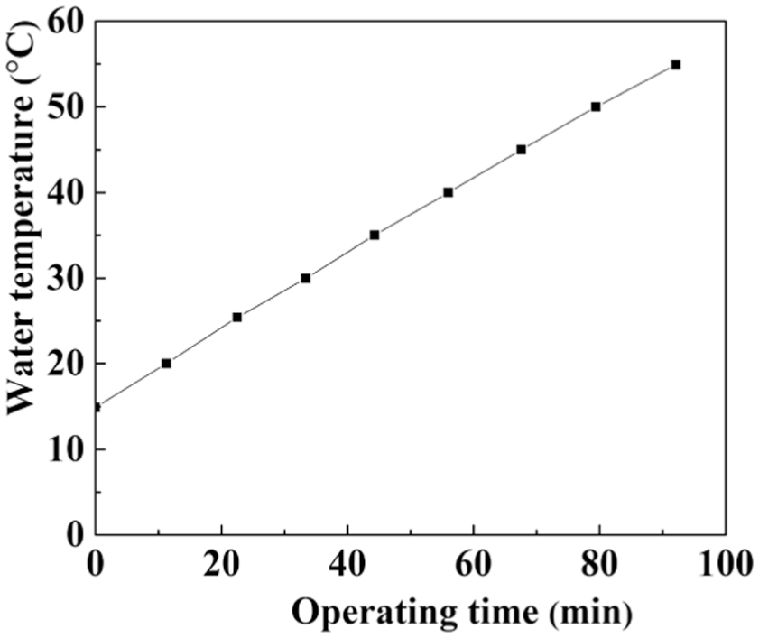
The heat absorbed by hot water from refrigerant consists of three parts: superheat refrigerant heat, latent heat, and sub-cooled refrigerant heat. Figure 2 displays the variations of mean water temperature versus operating time. It is evident that when the air-conditioner was operated, the water temperature experienced a gradual increase with the operating time, but the rate of increase of the water temperature gradually decreased. This indicates that the increase in water temperature reduced the transfer efficiency of the heat recovery exchanger as a function of the difference between the water and refrigerant temperatures. The heating of hot water from 20°C to the final temperature of 55°C took approximately 95 min per heating cycle.
Variations in hot water temperature with operating time in condensing heat recovery for water heating mode.
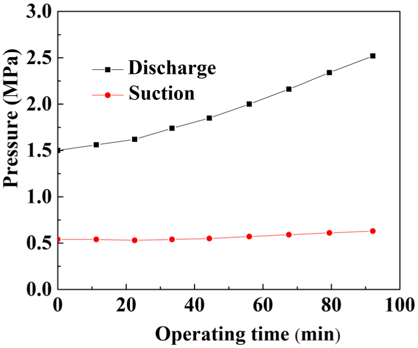
Figure 3 illustrates the variations in discharge and suction pressure with operating time; it is seen that the discharge and suction pressures improved up as time passed. The continuous rise in the discharge pressure led to a gradual rise in the ratio of the discharge and suction pressures (i.e. compression ratio) within the range of 2.96–4.31; hence, a continuous decrease in both the volumetric efficiency of the compressor and mass flow rate of the refrigerant was noted. The ratio of discharge and suction pressures is less than the acceptable limit of 10 suggested by the compressor manufacturer. 25

Variations in the discharge and suction pressure with operating time in condensing heat recovery for water heating mode.
The continuous increase in the discharge pressure is because the condensing heat exchanger was designed to operate in the standard condition. As water temperature increases with respect to operating time, the heat rejection performance between the refrigerant and water decreases to raise the condensing pressure to allow heat rejection.
The slight increase in suction pressure with the operating time is because of that the flow rate of refrigerant into the evaporator through the capillary tube is dependent on the ratio between the discharge and suction pressures, due to the negative regulation of the capillary tube, and the increasing amount of the refrigerant entering the evaporator increases the evaporation pressure value. 26
As noted in Figure 4, both the discharge temperature (40.7°C–71.3°C) and suction temperature also exhibit an increase, and their difference increases as the operating time increases. The increase in the discharge temperature is because the rate of refrigerant flowing through the compressor decreases to reduce the cooling effect of the refrigerant to the compressor with respect to the decrease in the volumetric effectiveness of the compressor. The maximum discharge temperature is 71.3°C, which is below the permissible limit of 105°C according to the characteristics of the lubricating oil to ensure the safe operation of the compressor. 27 The slight increase in the suction temperature is caused by the increase in the amount of refrigerant entering the evaporator, thereby leading to an increase in the evaporation temperature of the system.

Variations in the discharge and suction temperature with operating time in condensing heat recovery for water heating mode.
Figure 5 shows the variations in the degree of both sub-cooling and superheat. The degree of sub-cooling is taken as the temperature difference between the saturated refrigerant and the refrigerant at the condenser outlet, and the degree of superheat is defined as the temperature difference between the saturated refrigerant and the refrigerant at the evaporator outlet. As seen from Figure 5, the degree of both sub-cooling and superheat is reduced with the operating time.

Variations in the degree of sub-cooling and superheat with operating time in condensing heat recovery for water heating mode.
A plausible explanation for the reduction in the degree of sub-cooling is the degradation in the heat rejection efficiency of the condensing heat exchanger in response to the decrease in the water temperature due to the reduction in the amount of vapor refrigerant condensed in the heat recovery exchanger. The reduction in the degree of superheat is because of the continuous increase in the amount of refrigerant in the evaporator in response to the ratio of discharge and suction pressures for the passive control provided by the capillary tube. A lower superheat would increase the flooding risk of the compressor.
Flash gas (vapor content, xiev) presented at the evaporator inlet will decrease the space cooling capacity, and it can be computed as shown below

where hiev represents the refrigerant enthalpy at the inlet of the evaporator, kJ/kg; hsl represents the enthalpy of the saturated liquid refrigerant, kJ/kg; and hrl represents the refrigerant latent heat of evaporation, kJ/kg.
The enthalpies in equation (11) are determined using a series of empirical formulas. 28 In this case, hiev is equal to the refrigerant enthalpy before the capillary tube, and it is computed according to the corresponding pressure and temperature.
Figure 6 shows the variation in xiev with operating time, revealing that there is a continuous increase in xiev with the progression of time. This can be explained by the fact that when the water temperature increases with respect to time, it leads to a reduction in the degree of super-cooling. For achieving the required evaporating temperature, a large amount of flash gas is produced during the expansion process, which results in a lower proportion of the liquid refrigerant obtainable for evaporation.

Variation in xiev with operating time in condensing heat recovery for water heating mode.
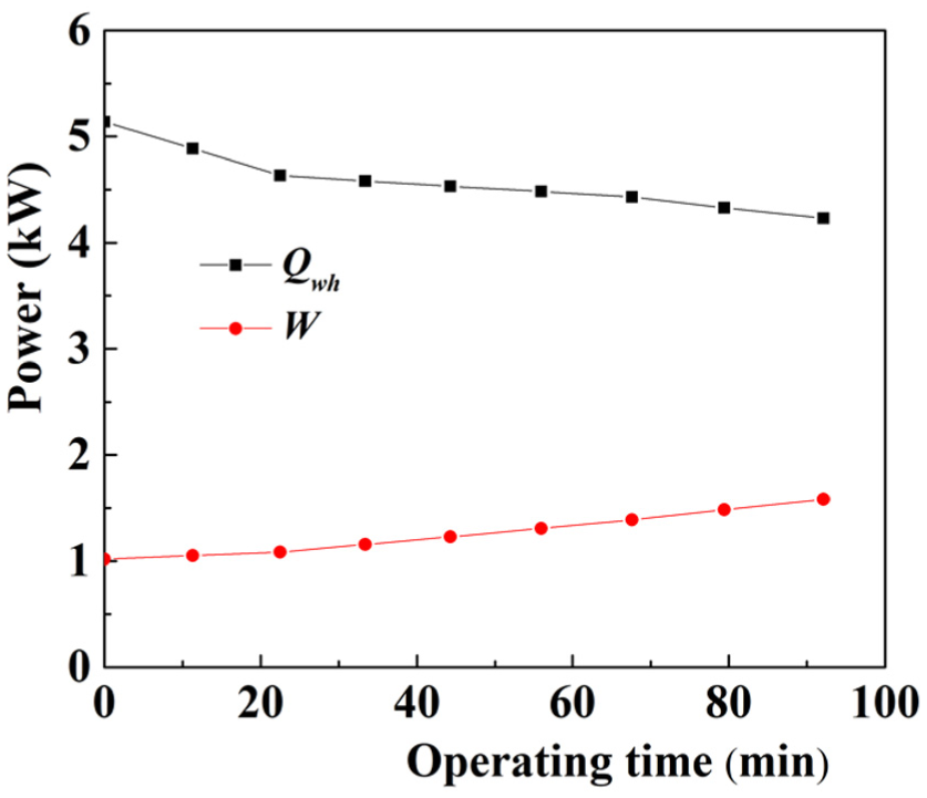
Figure 7 illustrates the changes in Qsc, Qwh, and W for the system against the operating time. It can be observed that both Qwh and Qsc exhibit a continuous decline, while W displays a constant increase with operating time, and Qwh is greater than Qsc.

Variations in power with operating time in condensing heat recovery for water heating mode.
The continuous decrease in Qwh is because the reduction in the difference between the water and refrigerant temperature decreased the amount of heat rejection in the condensing heat exchanger. The constant decrease in the volume efficiency of the compressor is another reason for this, despite this process being companied by an increase in the refrigerant heating power per unit mass. The average water heating capacity was computed to be approximately 3751 W.
The gradual decline in Qsc can be attributed to the reduction in the refrigerating capacity per unit quality of refrigerant due to the increase in xiev. This is in line with the reverse Carnot cycle theory, even though the process is accompanied by an increase in the refrigerant flow rate. The computed mean Qsc was 3400 W, which is similar to that in the space cooling only mode.
The incessant increase in the overall consumption power is attributable to the increase in the compression work per mass of refrigerant, although the process being accompanied by a gradual reduction in the mass flow rate of refrigerant flowing through the compressor. After analysis and calculation, the value of W was approximately 1320.5 W, which is larger than that of the space cooling mode by approximately 275 W.
Figure 8 displays the variations in COPwh and COPsc with the operating time, indicating that the COP of the system experienced a stepwise decline with the operating time as a result of a proportionate increase in W and decrease in Qsc and Qwh. The practical calculation results revealed that the average COPsc was 2.58, a reduction of approximately 0.27 compared to the corresponding value in the space cooling only mode; the average COPwh was 2.84. Even though the value of COPsc decreased, the hot water could still be obtained without a large cost at this time. The overall average COPcw value reached up to 5.42.

Variations in the COP with operating time in condensing heat recovery for water heating mode.
If a conventional electric water heater with an efficiency of 0.9 is used, 29 when the hot water in the water tank is heated from the original temperature of 20°C–55°C, the total electric energy consumption is approximately 6.78 kWh (equation (12))
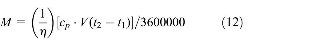
where M represents the electric energy consumption, kWh; η represents the electric efficiency of an electric water heater.
It is reasonable to note that some heat loss would occur in the air-cooled condenser and the connecting pipe during the process of heat recovery for the structure of the system. However, the refrigerant could further be cooled, thereby enhancing the performance and efficiency of the system.
In this case, the heat recovery rate (k) is defined as follows

where hicom represents the refrigerant enthalpy at the inlet of the compressor, kJ/kg; hocom represents the refrigerant enthalpy at the outlet of the compressor, kJ/kg; hihre represents the refrigerant enthalpy at the inlet of the heat recovery exchanger, kJ/kg; and hohre represents the refrigerant enthalpy at the outlet of the heat recovery exchanger, kJ/kg.
Figure 9 shows the variation in k with operating time, revealing that there is a continuous increase in k with respect to time. Although partial heat loss occurs in the air-cooled condenser, the refrigerant is further cooled, increasing the degree of sub-cooling and thereby enhancing the performance and efficiency of the system.

Variation in k with operating time in condensing heat recovery for water heating mode.
Air-source water heating performance
In the air-source water heating mode, the variations in the operating parameters of the heat pump were similar to those in the heat recovery for water heating mode, as illustrated in Figures 10–14. To avoid repetition, the reasons for these are not described in detail in this section.
Variations of water temperature with operating time in air-source water heating mode.
Variations in the discharge and suction pressure with operating time in air-source water heating mode.

Variations in the discharge and suction temperature with operating time in air-source water heating mode.
Variation in the power with operating time in air-source water heating mode.

Variations in the COP with operating time in air-source water heating mode.
Figure 10 illustrates the relationship between the mean water temperature and operating time. It is evident that the variation in water temperature was similar to that in the heat recovery mode with operating time, that is, the water temperature gradually increased and the increasing rate of temperature decreased. The mean hot water temperature reached up to 55°C from 15°C in approximately 98 min.
Figure 11 shows that the variations in discharge and suction pressure in are similar to those in Figure 3, in that an increase in the water temperature resulted in an exponential rise in the discharge pressure, and a slight increase in the suction pressure. The ratio of suction and discharge pressures exhibited a continuous increase.
As explained in the previous section, the exponential rise in discharge pressure is caused by a decrease in heat rejection performance between the refrigerant and water; the slight increase in the suction pressure is the result of an increase in the amount of refrigerant entering the evaporator through the capillary.
Figure 12 shows the variations in suction and discharge temperatures with operating time; a significant increase in discharge temperature and a slight rise in suction temperature are noted. The significant increase in discharge temperature is mainly due to the reduced cooling effect of the refrigerant on the compressor due to the decreased rate of refrigerant flowing through the compressor. The slight increase in the suction temperature is due to the increase in the amount of refrigerant flowing through the capillary into the evaporator, resulting in an increase in the evaporation temperature.
Figure 13 shows that the Qwh has a tendency of decreasing with operating time, while the opposite trend is true for power consumption. The continuous reduction in Qwh can be attributed to the continuous decrease in temperature difference between the water and refrigerant and a constant reduction in the compressor volumetric efficiency. The continuous increase in W is caused mainly by the increase in the compressor work of per unit mass of refrigerant.
The Qwh was calculated to be approximately 4551 W, and the W was approximately 1154 W. It is observed that the COPwh was dependent on the variations in operating conditions, as illustrated in Figure 14. When the water temperature increased with the running time, COPwh showed a rapid downward trend due to the continuous decrease in Qwh and the constant increase in W. The mean value of COPwh was calculated to be 3.94, which is approximately 4.38 times the corresponding value for the electric water heater.
Error analysis
The error of the test results could be calculated based on the accuracy of the instruments listed in Table 3. The error is determined using a set of independent variables calculated using equation (14). The final results were calculated using equation (15)30,31


The errors of COPsc, COPsh, COPwh, and COPcw are calculated by equations (16), (17), (18), and (19), respectively


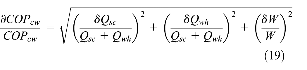
The calculation results indicate that the errors of COPsc in space cooling mode, COPsh space heating mode, and COPcw in condensing heat recovery mode are 2.98%, 2.90%, and 2.26%, respectively; the error of COPwh in the air-source water heating mode is 2.19% under an outdoor temperature of 20°C. All the calculation results are less than 10% of the maxmum value recommended by ISO 32 , so they are all within the allowable range.
Conclusion
The proposed DCHRAC has the advantages of simple structure, easy placement, low cost, high reliability, and easy control. The thermal performance in each operating mode was studied experimentally; the test results clearly indicated that the DCHRAC can be operated flexibly in various modes according to user demands; the specific test results are as follows:
In the summer and winter seasons, normal cooling and heating functions are sustained.
In the condensing heat recovery mode, the cooling capacity was basically equal to that in the single refrigeration cycle with an average COPsc of 2.58 when the hot water was heated from 20°C to 55°C. The overall average COPcw reached 5.42, which is an increase of 84% compared to the corresponding value in the single space cooling mode, despite a partial loss of heat due to its special structure.
When the air-conditioner worked as an air-source heat pump water heater in the transitional season, the average Qwh was 4551 W, while the average COPwh was 3.94 as the water temperature was varied from 15°C to 55°C.
Therefore, the DCHRAC has a high utilization rate and remarkable energy-saving effects. Thus, the research results can provide a valuable reference for future production of condensing heat recovery air-conditioners.
Footnotes
Appendix 1
Handling Editor: Assunta Andreozzi
Author note
Author Fuqiang Qiu is also affiliated to College of Energy and Power Engineering, Henan College of Animal Husbandry Economics.
Declaration of conflicting interests
The author(s) declared no potential conflicts of interest with respect to the research, authorship, and/or publication of this article.
Funding
The author(s) disclosed receipt of the following financial support for the research, authorship, and/or publication of this article: This work was financially supported by scientific research and innovation project of Shanghai Education Commission (14ZZ133), Shanghai alliance program project (LM201651), and Higher Education Key Science Fund Project of Anhui province (KJ2016A711).