
Abstract
In recent years, unmanned aerial vehicles have gained increasing popularity. They are employed in many applications due to its features in terms of flexibility, low cost, and small size. Due to special structure of mechanical system for the quad-rotor helicopter (typical small-sized unmanned aerial vehicle), one of the main research fields for quad-rotor helicopter is to improve its stability flight control so as to well implement its autonomous navigation. However, for the quad-rotor helicopter whose power is supplied by battery, the embedded operating system directly affects its flight performance; thus, it is of very importance to implement this goal. This article aims to put forward a high-performance software platform consisted of embedded operating system and JAVA virtual machine in the quad-rotor helicopter. Then, this article also proposes an autonomous control algorithm written by real-time JAVA application, which uses image entropy to avoid obstacles and optical flow to discover the most appropriate area to fly in while avoiding obstacles; besides, image identification with image contour detection is used for the cases of junction turn and landing. The practical experimental results show that the implemented software control platform and proposed autonomous flight application are component for indoor autonomous flight of quad-rotor helicopter.
Keywords
Introduction
In the recent years, quad-rotor helicopter as the typical unmanned aerial vehicle (UAV) has received an increasing attention from the research community. UAVs offer very great perspectives in many applications such as surveillance, patrolling, search, outdoor and indoor building inspection, real-time monitoring, high-risk aerial missions, mapping, fire detection, cinema recording, and so on.
Currently, real-time embedded operating systems VxWorks 1 and real-time executive for multiprocessor systems (RTEMS) 2 are used in the quad-rotor helicopters such as X4-flyer, 3 OS4, 4 Stanford testbed of autonomous rotorcraft for multi-agent control (STARMAC), 5 and Pixhawk. 6 But these operating systems are executed in the relative high-level hardware processor platforms. However, considering most hardware platforms adopted for quad-rotor helicopter are still low-level processor due to the design of low cost, developing a small-sized effective operating system kernel for quad-rotor helicopter is of very importance.
Besides, many researchers focus on the autonomous navigation control nowadays. Hoffmann et al. 5 presented a model-based algorithm for autonomous flying with their STARMAC-quad-rotor. Their system flied outdoors and utilized global positioning system (GPS) and inertial measurement. Achtelika et al. 7 developed an indoor autonomous quad-rotor equipped with a laser range scanner and cameras enabling autonomous hovering in a constrained indoor environment. Kendoul et al. 8 developed vision system for autonomous navigation three-dimensional (3D) localization and control of small aerial vehicles based on optic flow. Grzonka et al. 9 developed an indoor autonomous flight to estimate the elevation of the underlying surface by inertial measurement unit (IMU) accelerometers and laser so as to track and map multiple levels within an environment such as tables and chairs. For challenge of using only camera, Eresen et al. 10 implemented autonomous quad-rotor flight with obstacle avoidance in virtual environment, and their algorithm is tested in the Google Earth virtual environment for four different destination points. Rodriguez-Canosa et al. 11 proposed a real-time method to detect and track moving objects from UAV using a single camera, and the identification of moving objects is implemented by fusion of artificial flow and the real optical flow. But almost all of these researches are implemented by adding many others external sensors such as laser range scanner, GPS, RGB-D camera, and so on. So, for the quad-rotor helicopter only having the camera without other extra sensors, developing related autonomous navigation technologies is ought to be full of challenge for this article.
So far, the embedded operating system executed in the quad-rotor helicopter is responsible for the basic processing such as collecting image, receiving flight control signal, and so on. Besides, the complicated procedures such as processing the images collected are executed in the personal computer (PC). The high performance refers to the unique architecture consisted of embedded operating system and JAVA virtual machine; considering the advantage of real-time JAVA, establishing a middleware platform to show that real-time JAVA application can be executed in quad-rotor helicopter is significant.
The contribution of this article is that a high-performance software platform is proposed for the quad-rotor helicopter, so the quad-rotor helicopter can perform flight applications based on it. Besides, the single camera located in the quad-rotor helicopter is used to avoid obstacles; thus, the quad-rotor helicopter can implement the autonomous navigation while flying to the destination. In the process of autonomous navigation flight, optical flow and image entropy are used to detect and avoid obstacles, and the image identification with image contour is adopted in the cases of corner turning and landing. The whole autonomous flight control includes takeoff, autonomous flight with obstacle avoidance, and landing in specific destination point.
This article is organized as follows: section “Flight model of quad-rotor helicopter” presents the flight model of quad-rotor helicopter and its physical parameters. Section “Software platform designed for the quad-rotor helicopter” demonstrates the implemented high-performance software platform consisted of operating system kernel and JAVA virtual machine. Comparisons about two important performance parameters of the task switching time and maximum interruption inhabit time with existing operating systems are presented. Section “Autonomous flight control algorithm proposed for quad-rotor helicopter in the indoor environment” presents the optical flow, image entropy algorithm, and image contour detection, respectively. Section “Flight experiments in the indoor environment” presents the proposed autonomous control algorithm of obstacles avoidance based on optical flow and junction turn based on image entropy and image identification and experimental results about autonomous flight experiments in the indoor environment. Concluding remarks are given in section “Conclusion.”
Flight model of quad-rotor helicopter
Quad-rotor helicopter can generate different push on each propeller by controlling motor speed. Thus, the quad-rotor helicopter can execute the flight attitudes such as vertical takeoff and landing, pitching, rolling, and yawing. So, the quad-rotor helicopter is flexible enough to carry out some hard tasks, even in harsh environment.
As Figure 1 shows,
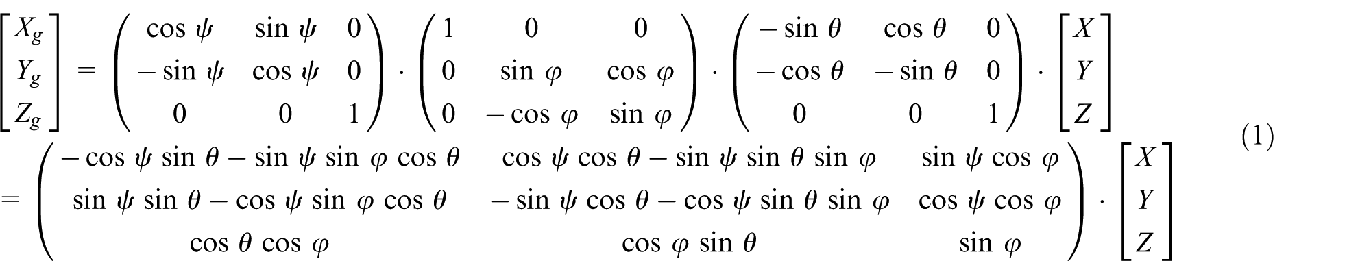
where lines

where variables u1, u2, u3, and u4 represent the lifting force, rolling force, pitching force, and drifting force, respectively. In the meantime, the input variable contains three other flight attitude information of

Coordinate transformation between quad-rotor helicopter and ground and flight attitude principle.
Software platform designed for the quad-rotor helicopter
Design and implementation of operating system kernel
For the quad-rotor helicopter, the designed operating system kernel was composed of the following four parts: task management, task communication, interruption processing, and timing.
Task management module
The basic function is to effectively manage the 16 tasks consisted of the whole application for the management module, and it provides the methods such as establishing a user task, deleting a task, checking the function ID (FID) of the task, and hanging up a task. The six implemented system calls (subprograms) are described as follows:
CREATE TASK: Establish and manage task dynamically;
DELETE TASK: Delete a specific task in the system;
GET FUNCTION ID: Obtain the ID number of certain task, whose value ranges from 00H to FFH;
WAIT: Suspend an executing task;
GET MEM: Obtain the beginning address about the memory of the available task with specific length in the system;
RELEASE MEM: Return certain memory with specific length to the system.
A total of two task establishment methods are designed. (a) Static establishment—while the system is initializing, the task is established by the user according to the format of task ID (ITD) table. (b) Dynamical establishment—input parameter is pointer number of task, and it stores beginning address of task ITD while establishing the task, and output parameter is task ITD, and its meaning is described as follows:
Success: this means the ITD value of the task, whose value ranges from 0 to 15.
Failure: the false reason is stored, which is expressed as 8XH.
In short, the system uses ITD table so as to generate a task dynamically; if successful, then the task with the smallest ITD is generated; otherwise, the false reason will be stored. While establishing a task in the phase of system initialization, the following tables designed are also need to be initialized.
Fill in TASK_BUF_BLOCK_TAB: Store length and beginning address that the task applied for;
Fill in TASK_PRR_TAB: Store the priority of the task;
Fill in INT_MASK_TAB: Store the interrupt bit vector of allowed interruption while task having certain priority is executing;
Fill in TASK_INT_TAB: Store the interruption bit vector of task;
Fill in INT_SOUREC_TAB: Store the related ITD value of certain interruption source;
Fill in FID_TAB: Store the FID value of certain task;
Fill in TASK_ADDR_TAB: Store the beginning address of task code;
Fill in TASK_MSG_TAB: Store the amount of message in the information queue of task, the beginning address of both the first task and the final one.
In order to well differentiate the task, the FID value is introduced to represent the task character besides the ITD value, and the correspondence between the IFD value and the task character is flexibly defined by the user, which means the user can recognize the task by the FID value, but for the system, it can only use the ITD value to differentiate the task, because it is generated by the system to describe the order number while the system generates the tasks.
When the system executes the DELETE TASK system call, the task will no longer exist, and the occupied system resource such as ITD vale and stack will also return to the system and make them available for establishing new tasks; in the meanwhile, the system supports that a task can delete itself. When a task is deleted, the following operations will be executed.
Withdraw all the related interruption resources for the task;
If the task is established using the dynamical system call CREATE TASK, then its stack will also need to return to the system buffer poll;
ITD value is available for a new task;
Terminate the time interval and time-out set for the task;
Change FID value of the task to 0;
Clean the date storage unit parameter of the task;
If the deleted task is in the ready status, then it will be removed from the task ready tab;
If the deleted task is running, the system will choose a new task from the task ready tab and make it run or change to the idle status (while there is no tasks in the task ready tab).
Two memory management methods are designed. (a) System initialization—when the system is initialized, system memory pool (SMP) is established and modified and then SMP is established by SUB1 subprogram. When task establishment is needed, the system uses CREATE10 subprogram to establish stack for these tasks in the top of SMP, then the stack having specific length is generated for these tasks, and, finally, the buffer block with fixed length called system buffer pool (SBP) is established. SMP is divided into SBP as much as possible, and the SBP established is linked with each other. (b) Dynamical establishment—when the system is executed, the system uses the subprograms CREATE10 and SUB1 to manage the system memory. When the system establishes a new task, if the left SMP is not big enough to allocate the stack that the task needed, then SUB1 subprogram is continuously executed so as to return SBP to SMP and then CREATE10 is used to allocate the stack the task needed, and SBP is established again from the left SMP.
Task communication module
Task communication means tasks can transfer date by the method of conveying message between different tasks. Then, tasks can implement synchronous operation and share system resources. Task communication provides services such as allocating buffer area, sending a message to another task, hanging up a task to wait for another message, and deallocating buffer.
The four implemented system calls are described as follows:
ALLOCATE: Establish memory buffer area for the message to be sent;
SEND MESSAGE: Send the message to the destination address;
WAIT MESSAGE: Order the task to wait for the coming of message;
DEALLOCATE: Return the allocated message buffer area to the system memory.
The system uses the message method to send date or order between two tasks. When the system sends a message to the message queue, the message block pointer but not the message block is sent in fact. If the task has already executed the WAIT MESSAGE system call to wait for the message, then the message can be received by this task. If the message does not come, then the task will be changed to the waiting status, and a new task will be chosen to execute, so the central processing unit (CPU) resource is also utilized in this case. When the message comes, whether it will enter the ready queue or become the execution status depends on its priority.
In order to well implement the autonomous flight of quad-rotor helicopter, considering the flexibility communication mechanism for the quad-rotor helicopter, two kinds of task communication methods are designed for the task execution of quad-rotor helicopter.
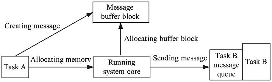
Single-line message mode. When task A sends date to task B, first task A will use ALLOCATE system call to obtain a buffer block and load date to it and then SEND MESSAGE system call will be executed so as to send the pointer to task B. The system sends message pointer to first in, first out (FIFO) message queue of task B. If task B has already executed WAIT system call to wait for a message, then it will receive message and access the message buffer block. If not, the pointer will be stored in the message queue temporarily, and the system will fetch the pointer until task B executes the WAIT system call, as shown in Figure 2.
Transaction processing mode. When task A sends message to task B, task A will allocate a buffer block by executing the ALLOCATE system call and store the order message into the buffer block and then will use the SEND MESSAGE system call to send the pointer of the message to task B. For the message queue of task B, if it has already executed the WAIT system call, then the pointer will be received, and it will access the buffer block; if not, the message will be stored in the message queue of task B.
Single-line message mode.
The above procedures are almost same with single-line message mode, but the subsequent process is different. After task B receiving the message, later it will change the message type from order to response and alter the source task and destination task, which means it will return it to the message queue of task A till it is fetched by task A, as shown in Figure 3.

Transaction processing mode.
Interruption processing module
Interruption processing service make task can communicate with external devices; besides, it provides services such as setting interruption source for task, disabling and enabling interruptions, and task synchronization with interruption. The three implemented system calls are described as follows:
DISABLE INTERRUPT: Disable interruptions;
ENABLE INTERRUPT: Enable interruptions;
SYNCHRONIZE: Synchronize task with interruption.
For the quad-rotor helicopter, the implementation of interruption directly affects the real-time ability of the system, so this article designs the common processing program COMMON_SERVER and TIMER0_ SERVER for timer0 interruption.
For the common interruption processing program COMMON_SERVER designed, the system first judges whether the system is in the idle status; if not, it will preserve the execution condition information. Later, the system checks the INT_SOURCE_TAB in order to obtain the task ITD related with the interruption source and then checks the ASLEEP_TAB so as to obtain the event-vector. If the second bit of the event-vector is 0, which means it does not wait for the coming of interruption, the pointer will point to the next unit (event-coming). The interruption bit vector will execute the “or” operation to reflect the interruptions; besides, the execution situation will be recovered. If the second bit of the event-vector is 1, which means it is indeed waiting for the interruption, then both the event-vector and the time-out will be cleared, and the task ITD will be compared with the ITD of executing task so as to decide whether the task will be switched.
For the TIMER0_SERVER subprogram designed, it mainly used to process the time interval and time-out in the ASLEEP_TAB, fill in the task ready tab and assign a task to execute, start the timer, execute task with highest priority, and so on. The detailed procedures are described as follows:
The system judges whether it is in idle status before timer0 interruption occurs; if not, the system will preserve the execution condition information. If the time interval is 0, then the system will judge the value of the time-out; if the time-out is not 0, then the system will process the time-out. If both time interval and time-out are 0, then the pointer will be modified in order to process the next task.
The time interval includes the following processing procedures: set the identification occupation bit of timer0. Subtract 1 for the time interval; if the time interval is not 0, then stop the time interval process to execute the time-out process. If the time interval is 0, then the task stores the time interval value to the ASLEEP_TAB. Fetch the second bit of event-vector and judge the second and third bits; if the task does not wait the time interval or is not the sleep status, then set the event-coming in the event-vector as 1, and the system turns to process the time-out. If the task is sleep status and waits for the time interval, then the event-vector is set as 04H, and the time-out is cleared. Finally, the system fills in the task ready tab and assigns a task to execute.
The time-out processing includes the following procedures: Subtract 1 for the time-out; if the value of time-out is not 0, then the system will judge the time interval and time-out for the next task. If the time-out is 0, then the event-vector will be cleared; later, the system will fill in the task ready tab and assign a task to execute. After processing about time interval and time-out of all the tasks, then timer0 is set, and the system will execute the task having the highest priority.
Timing module
The system uses timer0 to assign a soft clock to each task, and this soft clock provides the time interval and time-out. The time interval allows task to execute certain function during specific time interval, and time-out means the time that system allows the user to hang up a task to wait for certain event. The services include establishing time interval, waiting time interval, and time-out.
The two implemented system calls are described as follows:
SET INTERVAL: Set a time interval;
WAIT EVENT: Wait for the occurrence of the time interval and time-out.
If the system uses WAIT system call, then it will change task status to sleep status. When the event is finished, task status will be changed to ready status; if the priority of this task is high enough, then its status will be changed to execution, so CPU resources can be well utilized in this case.
The system hangs up a task so as to make it wait for the coming of certain event, after executing the WAIT system call, and it will check whether the waited task has already arrived; if not, the system will set the status of the task as wait and then obtain the time-out. If the value of the time-out is 0, it means no wait is needed in this case, so the task continues to execute without waiting. If the time-out is not 0FFH, the system will use the timing function. If the time-out is 0FFH, then the timing is not needed and then the task will be hanged up, and a new task will be chosen in the task ready tab to execute. If some events that the task waited come, then the system will check whether the task is waiting for message. If waited message comes, then the system will handle this message. If all events that the task waited come, then the task will begin to execute; otherwise, it will continue to wait.
The operating system designed for the quad-rotor helicopter implements the functions such as task management, task communication, interruption processing, timing, and so on. When users design the real-time flight application of quad-rotor helicopter, they only need to use these system calls so as to effectively implement the data collection, receiving control signal, and so on.
Design and implementation of JAVA virtual machine
Corporations SUN, IBM, and Microware put forward the real-time Java specification (RTSJ) considering the good performance of JAVA language. RTSJ extends the aspects in terms of memory management, thread scheduling, asynchronous event processing, and asynchronous control transfer on original JAVA, indicating JAVA can be applied to the real-time system. 14 For the processor of quad-rotor helicopter, it is responsible for the image collection and receiving the flight control demand sent by the PC, so a reduced JAVA virtual machine is implemented based on the FijiVM 15 (S3 lab at Purdue University in the United States, J.W. was a visiting scholar from September 2010 to September 2012 then). Only level 0 task application is implemented for the real-time JAVA application of the quad-rotor helicopter.
Based on the implemented quad-rotor helicopter operating system kernel, in order to show that the real-time JAVA flight control application can be executed in quad-rotor helicopter, a reduced JAVA virtual machine is implemented, as shown in Figure 4. Besides, this article also puts forward autonomous navigation technology including image entropy, optical flow, image identification, and implementations about these real-time JAVA applications.

Architecture of the whole quad-rotor helicopter control system.
For task in the system, its execution process can be divided into three phases: initialization, execution, and cleanup, as shown in Figure 5, and all tasks include the properties of releasing time, deadline, and priority.
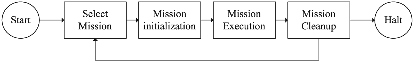
Task execution phases of real-time JAVA.
The design of reduced FijiVM (implementation with level 0 task) is shown in Figure 6. The memory allocation is described in this figure; four periodical task handlers are released at the same time, and each one has its own private memory. Once the next one is released, the last one can be cleared.

Illustration of level 0 task execution case.
Besides all class for the level 0 task executed in the quad-rotor helicopter, introduction, constructor, and included method are also described in Figure 7.
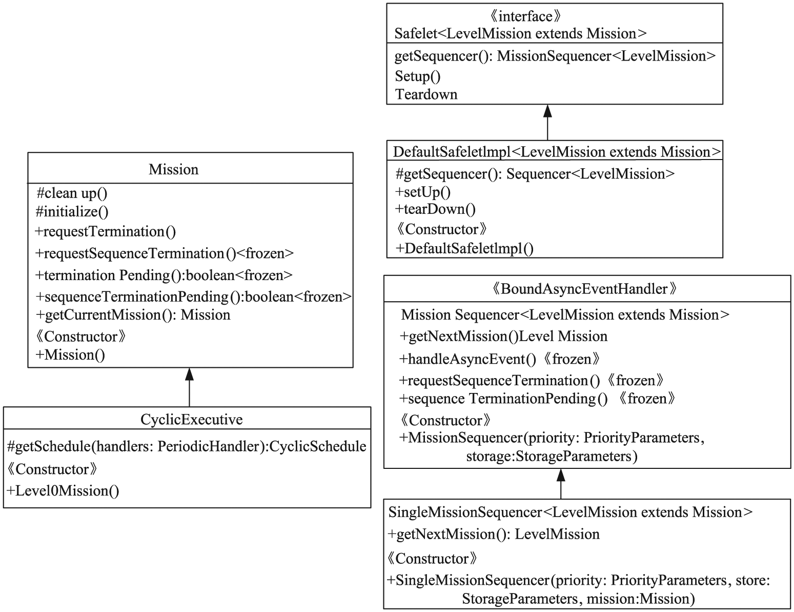
Class architecture of level 0 task.
Real-time performance analysis
In order to evaluate real-time performance of the quad-rotor helicopter OS, we mainly tested two performance parameters, namely, task switching time and maximum interruption inhabit time.
When the real-time operating system is performing certain system calls, it will not respond to the extra interrupt at once. Only when the OS switches to the user state, it can respond to the external interrupt requests, so the maximum time required for this process is called the maximum interrupt prohibition time.
The task switching time means that when a task is stopped running, the OS will store its running information to information queue and chooses a new task to execute, so this period of progress is called task switch time. Actually, it means the time that CPU suspends a task and switches to execute another one.
Then, comparisons with Webit5.0 OS16–20 and TinyOS 2.1.2 are presented. Embedded device Webit is developed by Liaoning Province Embedded Technology Key Laboratory, where I studied for my master’s degree and doctorate, 16 and it is the smallest embedded device then, which has obtained utility model product of China. The Webit5.0 OS is the fifth-generation operating system designed for Webit. Besides, we chose the TinyOS 2.1.2 as the comparison system because it also has relatively smaller kernel code size compared with other operating systems.
TinyOS is an open-source operating system, which is designed for low-power wireless devices. It is written in the nesC programming language. TinyOS started as the collaboration between the University of California, Berkeley, Intel Research, and Crossbow Technology. A worldwide communities from academia and industry uses and develops the operating system and its associated tools. TinyOS 2.1.2 is officially released on 20 August 2012. TinyOS 2.1.2 includes the following: support for updated msp430-gcc (4.6.3) and avr-gcc (4.1.2), complete 6lowpan/RPL IPv6 stack; support for the mini platform, ATmega128RFA1 chip, and so on.
We used the tools of logic analyzer (TLA603), arbitrary waveform generator (AWG2021), and digital storage oscilloscope (TDS1012). In the test programs, we added some control codes by transforming the value of high and low pulse levels through input–output (I/O) interface. For each experiment below, we tested 20 times and noted down the maximum and minimum values, as shown in Table 1.
Comparison about real-time system performance parameter.
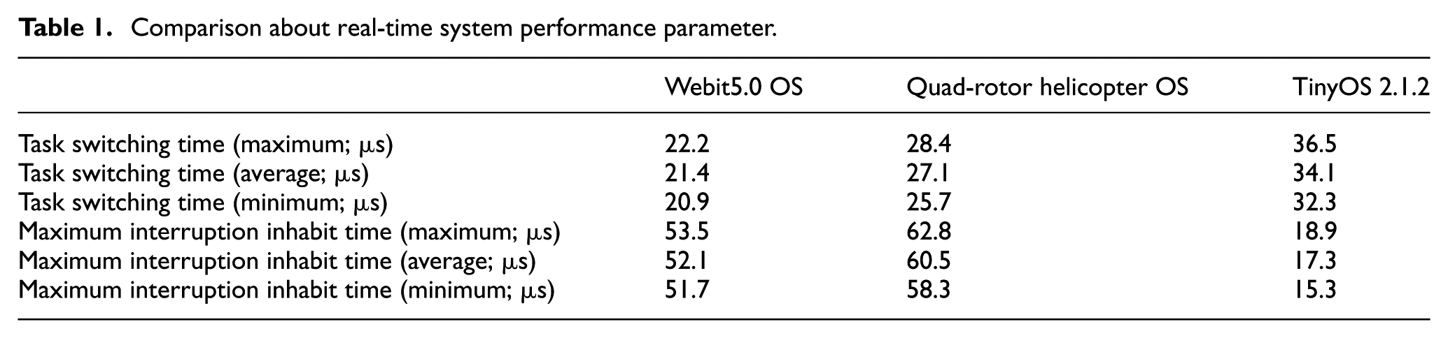
For the quad-rotor helicopter OS, the reduction of task switching time and maximum interruption inhabit time are longer than Webit5.0 OS’, due to the designed software of JAVA virtual machine between the OS and real-time JAVA application, which costs certain resources to some extent.
Compared with TinyOS 2.1.2, the task switching time of quad-rotor helicopter OS is shorter because of the special design structure of TASK_READY_TAB (16 memory units are used to store related information of every ready task. The low 4 bit stores the task priority, while the high 4 bit of each unit stores the task ITD. When a task is inserted into TASK_READY_TAB, it will be put in suitable place according to its priority so as to ensure that all tasks in the task ready tab are sorted by task priority.
But for the maximum interruption inhibit time, TinyOS 2.1.2 is better because the two kinds of interruption handling programs (COMMON SERVER and TIMER0 SERVER) take longer time for the Webit&NEU OS. However, the most important is that the high-performance software platform designed shows that real-time JAVA application is executable in the quad-rotor helicopter.
After implementation of the quad-rotor helicopter operating system kernel and reduced FijiVM, the real-time JAVA application can be executed in the quad-rotor helicopter. The following section will discuss the technologies implemented for the autonomous navigation of quad-rotor helicopter.
Autonomous flight control algorithm proposed for quad-rotor helicopter in the indoor environment
Optical flow technology for avoiding obstacles
Optical flow is the pattern of apparent motion about objects, surfaces, and edges in a visual scene, which is caused by the relative motion between an observer (a camera) and the scene. 21 Optical flow contains abundant information because it actually calculates the motion between two image frames; thus, it can be used to reflect moving objects for the quad-rotor helicopter.
In order to calculate the optical flow of image collected by the camera of the quad-rotor helicopter, the feature points in the image should be obtained first. The feature points are extracted by the Harris two-dimensional array

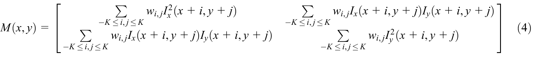
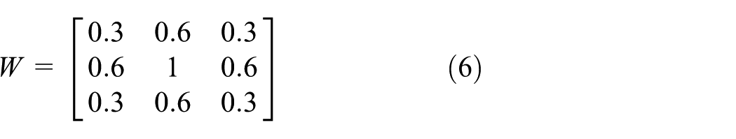
For the Harris feature points, each one uses the autocorrelation matrix of the image with second derivative, and the definition of the autocorrelation matrix is described in equation (4). Figure 8 shows the feature points detecting results about the two images collected by quad-rotor helicopter using this method

Shi-Tomasi feature points extraction: (a) test 1 and (b) test 2.
We adopt Lucas–Kanade (L-K) algorithm based on pyramid to obtain the optical flow and select the strong feature points so as to reduce the calculation burden; besides, the layer structure is used in order to solve the aperture problem. This process is executed using top-down approach.
For image frame I, the estimated error for optical flow in a certain window M is defined as

where
Finally, the optical flow can be obtained by

The algorithm used to obtain the optical flow about the images collected from quad-rotor helicopter is described as follows:
Step 1. Generate pyramid structure
Step 2. Initialize value of optical flow
Step 3. Calculate partial derivative of each feature point
Step 4. If
Step 5. Initialize optical flow residual
Step 6. Calculate the difference
Step 7. Calculate the optical flow residual
Step 8. Compare
Step 9. Obtain accumulated optical flow residual
Step 10. While reaching to the maximum iteration count, the final optical flow of k layer is
Step 11. Search the next layer of the pyramid, if
Step 12. Obtain the final optical flow
For the collected images from the camera of the quad-rotor helicopter, optical flow can well be used to identify the obstacles and conduct the autonomous navigation of quad-rotor helicopter.
Considering the principle that magnitude of optical flow velocity for near obstacles is larger than those in the far. The proposed system here utilizes this principle to detect obstacles so as to determine the allowed movement area in front of the quad-rotor helicopter. 22 The image collected by camera of quad-rotor helicopter is divided into two parts, left and right. If the sum of optical flow magnitudes of the left part is larger than the right part’s, then the system infers that the obstacle is located in the left area. Accordingly, the system will adjust the quad-rotor to fly toward the right side. Conversely, if the sum of optical flow magnitudes of the left part is smaller than the right part’s, then the system judges that the obstacle exists in the right part. Accordingly, the system will adjust the quad-rotor to fly toward the left side. The proposed optical flow control algorithm is presented as follows:
Generate the feature points of current image frame

where m and n mean the number of feature points in the left and right parts of the image, respectively.
Calculate the optical flow set of

where
Calculate the optical flows in the left and right parts of image, respectively

where m and n are integers.
Calculate the sum and average values of all optical flows in the left and right parts of the image, respectively

Set the threshold about the left part and right part of the image as
Calculate again the average value of set dpl and dpr, and the obtained two values are marked as Ml and Mr; the difference in values between Ml and Mr is regarded as control error so as to adjust the proportional control of the quad-rotor helicopter

Then, the system will adjust the desired yaw value as follows

If
Else if
Else If
Else If
Else If
Else If
Else If
Else If
Else If
Update the yaw angle
where K represents the factor of proportional control, and out is the output value used to control the roll value of the quad-rotor helicopter, so as to adjust the horizontal flight attitude of the quad-rotor helicopter.
In a word, the dense areas having large optical flow magnitude are regarded as obstacles, so quad-rotor helicopter will be adjusted to flight toward opposite direction in order to avoid these detected obstacles.
Junction turn and landing with image entropy and image identification
Junction turn in a corner using image entropy
In the field of information theory, entropy is a measure about the uncertainty in a random variable. 23 In this context, the term usually refers to the Shannon entropy, which is quantified as the expected value of the information contained in a message.
In order to describe the spatial feature of gray-level distribution, the average gray value of neighborhood is introduced on the base of one-dimensional entropy. The pixel gray with its neighborhood’s one together form the two-tuple characteristic, which is called as the two-dimensional entropy. For the two-tuple

where N denotes the scale of the image and
In order to describe the comprehensive features of certain pixel and its neighborhood pixel in terms of gray value and gray distribution, the two-dimensional image entropy can be defined as

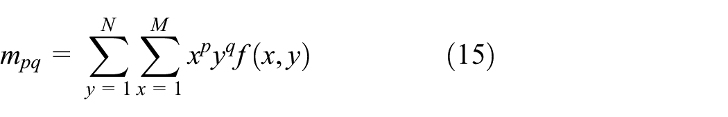
If an image contains less texture, accordingly its information contained is also less, so its entropy is relatively lower, and in this case, the probability that it is obstacle is smaller. Conversely, if the image contains more textures, then its information contained is also more; thus the entropy is higher, and in this case, the probability that it is obstacle is larger. From the above analysis, the system can judge whether the quad-rotor helicopter is flying close to an obstacle by comparing the current entropy with the given threshold.
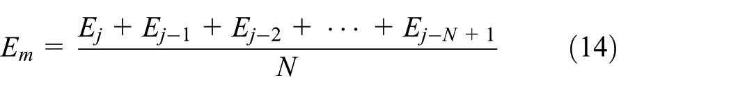
Using only the entropy of one image frame may cause large error. In order to decrease the error caused by real flight such as brightness mutation, after calculating the image entropy
The obstacle avoidance algorithm based on image entropy is described as follows:
Calculate gray-level histogram of current image frame;
Obtain image entropy of current image frame;
Use average filter to execute simple average filter according to entropy of recent N image frames
Compare
The threshold ET is obtained by specific flight experiments, which means the value varies according to the different indoor experiments. In order to set the threshold, the quad-rotor helicopter executes the flight close to the wall and records the entropy of every frame. Finally, the threshold is set as
In the indoor environment, while quad-rotor helicopter is flying close to obstacles, it can make an autonomous turn according to image entropy by the following procedures:
Judge whether quad-rotor is flying close to a corner by comparing the current image entropy with the threshold. If
During the given time interval t, if it judges that it is flying close to a wall again, then it will make a 180° turn, which means the last turn is wrong execution.
The turn is correct, and it will continue to fly.
Figures 9 and 10 show the experimental results using the image entropy, which are used to judge whether the quad-rotor helicopter is flying close to the white wall or the monochrome wooden door.
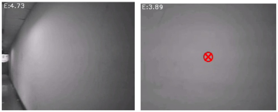
About close to the white wall.

About close to the monochrome wooden door.
The above case is the corner having only one channel (left or right). But for the case of T corner (two channels left and right in the junction), a flight sign of arrow is attached in the wall to indicate the flight direction. Besides, the landing sign of H is also attached in the ground, and these are implemented by image identification using image contour as described in the following section.
From the results, we can know that image entropy can well be used to judge whether quad-rotor is flying close to objects such as wall or door having simple color. When the image entropy calculated is close to the threshold, the quad-rotor helicopter will adjust its flight degree so as to avoid these obstacles.
Junction turn and landing using image identification
After the procedures of graying, binarization, and finding contours, the system pre-stores the template of flight sign. Moment is the obtained characteristics after the summation operation.
24
For the image collected by the quad-rotor helicopter, Hu moment technique is used to obtain the image contour. Supposing the image function is
where
Variables N and M stand for the height and width of the image, respectively. Normalization of center distance is defined by

where
Then, formula (15) can be expressed by

Hu moment is calculated by the center distance

After the image contour is identified, the system matches it with the pre-stored template. Then, the quad-rotor can adjust to make corresponding turn or prepare for landing according to the matching results.
In order to make the correct turn, the most important work is to identify the arrow attached in the wall. The system pre-stores the template of arrow after the process of graying, binarization, and finding contours. For the images collected by the quad-rotor helicopter, the same process is executed and then the system judges the
The implemented image identification system stores the set of X pixels about the matching contours first. Then, it calculates the average value
In the bottom of quad-rotor helicopter, a camera is used to locate landing point in fight experiment. When quad-rotor helicopter identifies landing sigh H, it will prepare for landing.
The whole control process includes takeoff, autonomous flight, and landing in a specific destination point in the indoor environment. The workflow of the proposed autonomous control algorithm is described as follows: After takeoff, the quad-rotor helicopter is kept at the desired heights, that is, 1.5 m from the ground with the aid of proportional–integral–derivative (PID) controllers. Then, image identification system judges whether the quad-rotor helicopter is close to an obstacle by comparing the current image entropy with the given threshold and calculates the optical flow to obtain the desired yaw angle so as to avoid obstacles. Besides, in a junction, image identification with image contour is used to make a turn for the quad-rotor helicopter. During the whole flight process, PID control is used to control its flight attitude. Finally, the system judges whether it is flying close to the destination point by the bottom camera using image identification algorithm, as shown in Figure 11. The whole workflow of the proposed autonomous navigation control algorithm is described in Figure 12.

Workflow of image identification using contour detection.

Workflow of proposed autonomous navigation control algorithm.
Flight experiments in the indoor environment
Introduction of experiment platform
The adopted quad-rotor helicopter platform is AR.Drone, which is developed by Parrot Corporation, France. AR.Drone is designed based on four-axis intelligent controlling by Wi-Fi, and it has the sensors such as three-axis accelerometer, two-axis gyrometer, one-axis yaw gyrometer, and ultrasonic wave height meter. Besides, AR.Drone has a front camera (320 × 240 pixels, 15 fps) and rear camera (176 × 144 pixels, 60 fps), respectively.
Quad-rotor helicopter collects the sensors data such as gyroscope, accelerometer, and altimeter, and the system further calculates the navigation data such as attitude information of pitching, roll, yaw angles, and height. The quad-rotor helicopter sends these navigation data and video streaming to PC through Wi-Fi.25–28 Then, PC refreshes the current navigation data and handles the video streaming include decoding, video navigation, and image processing algorithms. After PC calculating the navigation error according to the output of visual navigation, the system sends the navigation error to the PID controller and, finally, obtains the output of flight control command. The output is sent to quad-rotor helicopter by Wi-Fi to effectively control the flight of quad-rotor helicopter.29–32
Flight experiments in the indoor environment
In order to test the proposed algorithm, it has been tested within the platform AR.Drone in the indoor environment. The fight experimental results are presented by three cases of no obstacles, obstacles, junction turn, and landing as follows:
1. Test of avoiding obstacles. The flight environment adopted is indoor corridor, Figure 13(a)–(c) shows the cases while quad-rotor is flying in the center, left, and right of the corridor environment, respectively. The red arrow is the generated optical flow caused by the movement of the quad-rotor helicopter, and the green arrow indicates that the next flight direction adjustment for the quad-rotor helicopter should be adopted.

Flight deviation detection using optical flow: (a) center, (b) left, and (c) right of the corridor environment.
The system calculates the optical flow sum of the left part and right part, respectively, for the collected images and judges the deviation direction according to the optical flow algorithm as described in section “Optical flow technology for avoiding obstacles” so as to obtain the desired yaw angle.
As Figure 14(a)–(c) shows, the area having larger optical flow sum is regarded as obstacles. So, quad-rotor helicopter will adjust itself to fly toward opposite direction as the green arrow indicates, in order to avoid flying close to the wall.

Flight obstacles detection using optical flow: (a) not near, (b) right, and (c) left obstacles in the corridor environment.
Besides, Figure 14 shows the flight experiments about detecting the obstacles during the flight process in the indoor environment. The quad-rotor helicopter can detect and avoid obstacles successfully, so the implemented optical flow can well used to detect the obstacles for the quad-rotor helicopter.
2. Junction turn and landing. These experiments are used to detect the flight sign of arrow attached in the wall and floor. As Figure 15(a) shows, while quad-rotor helicopter is flying close to wall, the mage entropy is continuously decreasing until it reaches to threshold ET and then quad-rotor helicopter infers that it is flying close to a wall and makes corresponding turn according to image entropy algorithm.

Cases of detection about junction turn and landing: (a) obstacle detection, (b) junction turn sign, and (c) landing sign.
When the flight sign of junction turn (attached on the floor) or landing (attached on the wall) is detected, the system will detect the contour and match it with pre-stored template according to the image identification algorithm using contour detection, as shown in Figure 15(b) and (c). Then, quad-rotor helicopter will make correct turn and prepare for landing. As the image contour can be successfully detected as the green lines show, so the system can make correct turn or landing according to the detection result. For many flight cases, the proposed autonomous flight control is successfully implemented in the quad-rotor helicopter without collisions occurring.
Conclusion
Real-time JAVA has shown very good performance in the field of embedded real-time system. A high-performance software platform consisted of embedded operating system and a JAVA virtual machine is designed for the quad-rotor helicopter in this article. Based on the implemented high-performance software platform, this article demonstrates the real-time JAVA application of optical flow information for autonomous flight, image entropy for avoiding obstacles, and image identification using image contour detection for junction turn and landing.
No extra flight information is provided to the quad-rotor helicopter, except for the turn direction in the junction and the destination point in the ground. The method proposed needs very small computational time, and the overall response of the whole system is acceptable, which makes quad-rotor helicopter component in autonomous navigation applications. The most important is that the designed high-performance software platform shows that real-time JAVA application can be executed in the quad-rotor helicopter.
Footnotes
Acknowledgements
The authors thank Jan Vitek, Ales Plsek, and Lei Zhao for their help while J.W. studied in S3 lab (research on FijiVM) at Purdue University as a visiting scholar from September 2010 to September 2012. The authors also thank the anonymous reviewers for their valuable comments.
Academic Editor: Nasim Ullah
Declaration of conflicting interests
The author(s) declared no potential conflicts of interest with respect to the research, authorship, and/or publication of this article.
Funding
The author(s) disclosed receipt of the following financial support for the research, authorship, and/or publication of this article: This work was supported by the Fundamental Research Funds for the Central Universities of Civil Aviation University of China (nos. 3122015C020 and 3122014P004), Major Projects of Civil Aviation Technology Innovation Funds of China (nos. MHRD 20140106, and MHRD 20150107) and Scientific Research Foundation of Civil Aviation University of China (no 2014QD13X).