
Abstract
A novel structure of the combined braking system based on the regenerative braking energy has been proposed to achieve simplified structure and energy-saving capability simultaneously, which includes the hydraulic regenerative braking system, electro-hydraulic braking system, and the power coordinate module. Theoretical contributions and managerial implications of the developed system are discussed. The corresponding mathematic models are developed, a fuzzy control method which can fulfill the power coordinate between the high-pressure and low-pressure accumulators is proposed, and the correctness of the model is verified with the utilization of the test bench. The dynamic characteristics and efficiency are further investigated in various parameters based on MATLAB/Simulink, such as the vehicle initial braking speed, the upper pressure, the liquid capacity, and the state-of-charge (SOC) of the regenerative braking accumulator. The results of the simulations which provide strong evidence for the liquid capacity and initial SOC of the regenerative braking accumulator are the key factors that affect the energy recovery efficiency, and the initial braking speed is the key point that affects the total energy. The results can provide analytical references to practical applications.
Keywords
Introduction
City buses are widely applied in our daily life. However, one remarkable drawback in their applications is the low energy efficiency, which mainly comes from the kinetic energy lost as heat energy during mechanical friction braking for the frequent go-stop patterns 1 and the higher braking intensity. 2 In a conventional braking system, about one-third of the energy of the power is wasted during deceleration. 3 Therefore, many effective methods have been proposed to recapture this wasted kinetic energy; energy recovery is an efficiency approach. A typical style is the hydraulic hybrid vehicle (HHV) with an energy recovery system, which presents the best solution for energy recovery. 4
The commonly used energy recovery system includes electric, mechanical, and hydraulic systems 5 , and energy can be recovered through hydraulic accumulator and electrical storage. Among those, the hydraulic system is likely to be 33% smaller and 20% lighter than the closest electrical counterparts and is therefore a logical selection for regenerative braking. 4 Previous research presented that the major research topic of improving the energy recovery efficiency in hydraulic systems is system design, 6 structure,7–10 and control strategy,11–13 all manners are needed to know the key factors and dynamic characteristics previously to improve the regeneration efficiency, although the modeling uncertainties can be obtained with the appropriate method. 14 Apart from the traditional hydraulic systems, the electro-hydraulic composite braking system (EHCBS), which features in high-power density and energy conversion efficiency, has been proven suitable for heavy duty vehicles. 15 However, the size and cost are the drawbacks because it needs an additional vacuum boosted system to supply the necessary power.
The EHCBS applied in hybrid electric city bus is widely investigated and commercialized. Typically, its efficiency is improved significantly with corresponding control strategy.16–18 Previous research presented that the parameter design according to the actual application conditions can substantially improve the energy recovery efficiency. 19 But the control strategy design is difficult because it includes a variety of nonlinear components. 20 For EHCBS, there are three indexes to evaluate its performance. First, the energy recovery efficiency should be acceptable; otherwise, the system is meaningless. Second, the nonlinear and dynamic feature should be acceptable and controllable; 21 otherwise, the control variable is not clear enough and the control effect is not ideal. Third, the structure should not be complicated than traditional system so that various required operations can still be performed normally. So, dynamic characteristics of the system should be acquired and the key factors that affect the energy efficiency are clearly a prerequisite for controlling the EHCBS efficient.
In addition to the aforementioned traditional methods, the efficiency of energy recovery will also increase if the regenerative braking energy can be fully utilized, such as to provide the necessary power to the other system and the board energy source could be reduced. By this way, EHCBS would have a simplified structure, a further improvement in size and cost, and have the same or higher efficiency.
In this research, a novel EHCBS is proposed which could fully take the advantage of recovered energy and has a rather simplified system structure. The hydraulic regenerative braking system, electro-hydraulic braking system, and power coordinate module have been considered as the main subsystems. The corresponding mathematic model, the control method, the dynamic characteristics, key factors, and efficiency analysis are further investigated, aiming to provide analytical and experimental guidelines for high-performance control method of new EHCBS.
Principle of the novel combined braking system configuration
The novel EHCBS configuration based on the regenerative braking energy is shown in Figure 1. The system includes three dominate subsystems: hydraulic regenerative braking system, electro-hydraulic braking system, and power adjusting module. The key devices consist of a hydraulic pump, proportional relief valves, directional valves, throttle valves, hydraulic accumulator, and sensors. Using this scheme we can design a more efficient and simple energy recovery system, where energy losses can be recovered in hybrid fluid form and reused to power the other systems. The configurations of the three subsystems are presented and analyzed as follows.

Schematic diagram of the EHCBS.
Hydraulic regenerative braking system
During the braking mode, the kinetic energy is recovered into high-pressure regenerative braking accumulator by hydraulic regeneration technique. When necessary, the hydraulic energy is allowed to flow into a hydraulic pump/motor–motor unit to drive the vehicle. Moreover, the recovery energy can also be used to charge the lower pressure electro-hydraulic braking accumulator and power the other systems. To improve the efficiency of the secondary unit, the high-efficiency hydraulic pump/motors has been employed.
Electro-hydraulic braking system
The key components of the electro-hydraulic braking system are lower pressure electro-hydraulic braking accumulator, electro-hydraulic brake valve, and the power regulator controller. The electro-hydraulic braking accumulator provides the correspondent power to the braking system through the electro-hydraulic brake valve according to the voltage signal converted from the brake pedal angle. Meanwhile, the electro-hydraulic braking accumulator can be charged by the regenerative braking accumulator when its pressure is not enough and been controlled with the power coordinated module. The power coordinated method is shown as follows.
Power coordinate module
The power coordinate module consists of 4 two-position two-port electromagnetic directional valves A, B, C, and D. The controller could detect the flow in/out pressures in both the regenerative braking accumulator and the electro-hydraulic braking accumulator. Then the electromagnetic directional valve is powered according to the corresponding control algorithm.
Station A
When the pressure of the electro-hydraulic braking accumulator is lower and the power of the regenerative braking accumulator is sufficient, then the electromagnetic directional valves B and C are closed and A and D are opened. The electro-hydraulic braking accumulator is charged by regenerative braking accumulator until the upper setting pressure of the electro-hydraulic braking accumulator is reached.
Station B
When the pressure of the regenerative braking accumulator is lower than the setting pressure, the electromagnetic directional valves A and B are closed, and the C and D are opened, then the regenerative braking accumulator is charged by the hydraulic pump.
Section C
When the pressure of the electro-hydraulic braking accumulator is lower and the power of the regenerative braking accumulator is not sufficient to charge, then the electromagnetic directional valves B and D are closed and A and C are opened, the electro-hydraulic braking accumulator is powered by the hydraulic pump to ensure adequate braking energy.
Besides the functions describe above, the excessive energy recovery in braking process can be reused to power the other systems by regulating the electromagnetic directional valve E.
Operating principle of the combined braking system
Taking into account the energy recovery efficiency and braking stability, the driver’s braking intention and brake pedal stroke can be divided into three cases: mild braking, moderate braking, and heavy braking, respectively.
In mild braking case, the system operates at the regenerative braking mode singly. In moderate braking case, the braking torque is produced from two sources: hydraulic regenerative braking accumulator and electro-hydraulic braking accumulator; the distribution ratio is determined by the state-of-charge (SOC) of two accumulators, but the dominate principle is recovering the kinetic energy as much as possible based on implementing a steady brake effect. In this condition, the electromagnetic directional valves A, C, and E are closed, and B and D are opened. In heavy braking case, the system only operates in electro-hydraulic braking model to ensure the braking stability.
Modeling and verification
Hydraulic regenerative braking system
When the braking torque is provided by energy recovery system, this condition can be regarded as pure regenerative braking. In this condition, the brake drag torque is converted from the braking energy regenerative system and the recovery energy is equal to the vehicle kinetic energy

where m is the vehicle mass, d is the differential symbol, v is the vehicle speed, r is the wheel radius, Ff is the rolling friction resistance, Fw is the air resistance,
Thus, the rotation rate

According to the motor modeling principle, the discharge flow and the moment equilibrium function of the motor can be written as


where
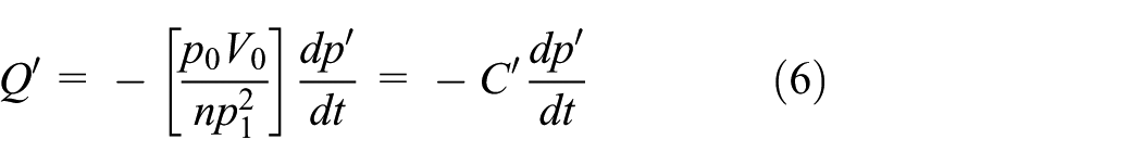
In general, the high pressure needed to fill the regenerative braking accumulator is generated from the output flow rate of hydraulic pump/motor because the liquid is incompressible. Neglecting the hydraulic tubing pressure loss, the liquid filling flow of the regenerative braking accumulator can be written as

where p and p0 are the inlet and filling pressure of the regenerative braking accumulator, respectively; V0 is the available capacity of the regenerative braking accumulator; n is the variable process index; and
Similarly, the liquid discharge flow of regenerative braking accumulator can be expressed as
where
Electro-hydraulic braking system model
Theoretical models of the proportional electromagnetic valve
With the advantage feature of short response time, the electromagnetic valve is commonly used as the main control device gradually in hydraulic control systems. 22 It is mainly formed by an armature, a coil, a spool, and a spring, as shown in Figure 2.

Mechanical model of electromagnetic valve.
A proportional electromagnetic valve consists of an electrical and magnetic circuit which could transform the input voltage that corresponds the control signal to an electromagnetic force on the spool of the valve; meanwhile, the armature displacement is proportional to the electrical current flowing through the solenoid. Therefore, the valve is actuated by means of proportional solenoids capable of modulating the flow rate according to an input signal. The equations describing the ideal voltage model are defined as follows

where
In general case, the proportional amplifier forming the deep current negative feedback is nonlinear and should be considered to obtain more accurate calculation method, but for EHCBS in HHV application where pressure and flow rate are not very large, the relationship between the feedback voltage and current, the output voltage as well as the given voltage can be regarded as linear. Based on those supposed, the control voltage

where
Combined with function (8), a rather simple but useful methods are obtained to convert the proportional solenoid voltage into keeper displacement relationship. The given voltage of the proportional amplifier can be transformed to

Then, the armature, the push rod, and the control valve are taken as a whole ignoring the clamping force; the force balance equation acting on the control valve according to Newton’s second law could be expressed as

where
Theoretical models of the electro-hydraulic braking accumulator
In regenerative braking, the hydraulic braking system is powered by hydraulic pump or regenerative braking accumulator. According to the fluid mechanics principle, the liquid filling flow of hydraulic braking accumulator may be expressed as
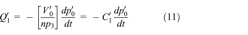
where
In power braking, the release process of the electro-hydraulic braking accumulator liquid is very fast and can be regarded as adiabatic process. So, the liquid discharge flow can be expressed as

where
Flow balance of the electro-hydraulic brake valve
The flow rate through the orifice area of the electro-hydraulic brake valve is the amount of the flow rate out of the electro-hydraulic braking accumulator and back to the tank, and the flow rate can be expressed as

where


Here

where
Theoretical models of the brake wheel cylinder piston
In the boost condition, the cylinder piston almost stay static, the main factors that affect the flow rate are the oil compression and elastic deformation of the spring. Therefore, the oil flowed into the cylinder
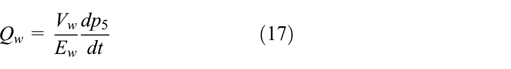
where
For the whole vehicle system, the pressure on the wheel cylinder piston is equal to the working pressure of the electro-hydraulic brake valve. So, the force on the wheel cylinder piston can be expressed as

where
Here, the flow rate of the hydraulic cylinder control chamber can be expressed as

where pc is the difference pressure in the hydraulic cylinder control chamber,
Power coordinate dynamic model
In power coordinate dynamic model, 4 two-position two-port electromagnetic directional valves are used to coordinate the high-pressure hydraulic oil by adjusting the valve opening or closing and reversing with the combine strength such as electromagnetic force, the inertial force, the spring force, the hydraulic force, and the viscous drag force. Based on the Newton second law, the relationship between the forces when the power supplied can be expressed as

where M is the quality of the valve core,
When the electromagnetic valve is not energized, the moving-iron and the valve core are moved under the force of the return spring and the oil inlet is closed, the reset motion can be expressed as

Energy recovery efficiency
In the vehicle braking condition, the total recovery energy is the vehicle kinetic energy and can be expressed as

where
So, the energy recovery rate in vehicle combined braking condition may be expressed as

Here

where
Fuzzy control of the power distribution
To obtain the combined effort of the combined braking system, a simple fuzzy control method is proposed to execute the power coordination between the high-pressure and low-pressure accumulators because the fuzzy control has good adaptability and robustness. 17 In power coordination process, the switch value of the brake stroke Z is very important for a precise estimation, taking into account the energy recovery efficiency and braking stability; the ranges of three kinds can be categorized as follows
When
When
When
Moreover, combined with the other control variables such as the SOC and pressure of the regenerative braking accumulator, the vehicle speed, the brake pedal stroke, and the fuzzy subset of the input parameters are designed as follows


The interface of the proposed fuzzy control method in MATLAB/Simulink is shown in Figure 3.

Interface of the fuzzy control method in MATLAB/Simulink.
Verification
The hydraulic power system test bench
To illustrate aforementioned designs and verify the proposed dynamic model of the novel structure, a test platform has been set up and is shown in Figure 4. The key component of the platform consists of a hydraulic pump (which powered by an electrical machine), some proportional relief valves, proportional throttle valves (which governs the outlet pressure of the oil source and can be used to simulate the multi-actuator effect by setting different values), electromagnetic directional valve, a high-pressure accumulator, four lower pressure accumulator, and a dSPACE controller. In dSPACE, the A/D and D/A conversion interface can achieve the conversion of the digital signals and the analog signals. The real system components can be connected to the dSPACE expansion board instead of the target control system in the simulation model.

Architecture and main equipments of the test bench.
The test bench is also equipped with various sensors including flow meters, pressure sensors, current sensors, and voltage sensors to evaluate energy losses and efficiency and can be controlled. For implementation of the verification, liquid pressure and flow rate in power line have to be obtained and monitored.
In hydraulic regenerative braking station, the filling process of the high-pressure accumulator is powered by electrical machine and the energy recovery process is simulated, the pressure range is determined by proportional throttle valve and the fluid flow rate is controlled by proportional relief valve. The implementation of electro-hydraulic braking force controls the proportional relief valve opening size, which is controlled by dSPACE according to the signal detected by the brake pedal. In this way, the electro-hydraulic braking pressure changes the proportional relief valve opening size and the hydraulic regenerative braking process is tested. The electromagnetic directional valve, which governs the direction of the high-pressure hydraulic oil, can be used to simulate the power coordinate effect by setting different ways of switching. The directional valve is controlled by the message translated from the electrical current signal which properly corresponds to the pressure. In this manner, the vehicle working state can be simulated.
Validation
The accumulator charging–discharging experiments in two typical corresponding conditions are implemented on the test bench with the determined parameters; the validation results are as follows. The key actuator physical parameters and vehicle tested parameters are listed in Table 1.
Key parameters of the system.
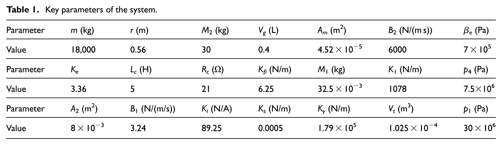
In order to better close the further practical application, the minimum and maximum pressures of the regenerative accumulator are set to 15 and 25 MPa, respectively. The hand-held recorder HMG 3000 is employed to record the pressure feature in pipeline. The comparison of the test results and the simulation results with the corresponding condition is shown in Figures 5 and 6, where the recoverable energy varying with time can be observed.
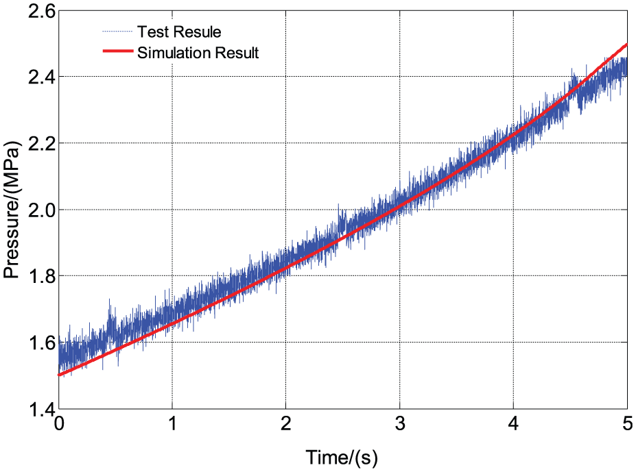
Comparison in energy recovery condition.

Comparison in energy release condition.
It can be seen from Figure 5 that the simulation curve is similar to the experimental curve. In the initial phase of the test, the experiment result is higher than the simulation results, where the hydraulic tubing has low pressure loss in lower pipeline pressure. At the end of the test, the experiment result is lower than the simulation results, where the hydraulic tubing has more pressure loss in high pipeline pressure. The regenerative accumulator pressure achieves the maximum pressure in 5 s, which demonstrates that the platform and the mathematical model can accurately reflect the dynamic response characteristics of the energy recovery process. It is observed from Figure 6 that the regenerative accumulator pressure reaches the limit 15 MPa in 3.5 s, which demonstrates that the simulation model can accurately reflect the dynamic response characteristics of the energy release process.
In summary, the mathematical model of the combined braking system can accurately reflect the dynamic response characteristics of the real system. Moreover, the linearity assumption of the model does not affect the model accuracy in the vehicle hydraulic application.
Simulation evaluation
According to the mathematic model and the proposed fuzzy control method of the combined braking system, the virtual simulation platform is set up in MATLAB/Simulink environment and used to perform further analysis, as shown in Figure 7.

Simulation model of the novel combined braking system.
Dynamic characteristics of regenerative braking system
In order to obtain the effects of minimum and maximum pressure and the dynamic characteristics of the regenerative braking system, we set the minimum filling pressure to 15 MPa, analyze the dynamic feature under three different maximum limits 25, 27, and 31 MPa. Meanwhile, we set the maximum pressure to 27 MPa and obtain dynamic feature under three minimum pressures 15, 17, and 19 MPa. The pressure dynamic features at corresponding circumstances are recorded, respectively, as shown in Figures 8 and 9.

Pressure change under three upper pressures.

Pressure change under three initial low pressures.
As Figure 8 shows, it takes longer to reach the same energy level at higher upper pressures and the recovery rate gradually becomes slower in energy recovery process, and the corresponding times are 4.7, 5.7, and 8.5 s. It can also be observed that it takes longer to reach the same energy level in energy release process with the increasing upper pressure, but the energy release rate held constant, and the corresponding times are 7.5, 8.8, and 10.6 s.
According to Figure 9, lesser time is needed to reach the same energy level at the higher initial pressure. The recovery rate gradually becomes faster in energy recovery process, and the corresponding times are 3.5, 4.5, and 5.8 s. In energy release process, lesser time is needed to reach the same energy level with the increasing initial pressure while the energy release rate remains constant, and the corresponding times are 5.6, 8.8, and 10.6 s.
In summary, the upper pressure of the regenerative accumulator has a significant effect on the energy recovery process but has a slight influence on the energy release process. The system can satisfy the use of requirements of the vehicle system, and the respond time in energy recovery condition is shorter than the energy release condition.
Dynamic characteristics and efficiency of the combined braking system
Effect of the initial braking speed
The pressure of the regenerative braking accumulator is set to 15 MPa, the maximum pressure to 31 MPa, and the initial SOC is confirmed at 0, and then the simulation tests are carried out at four speeds 20, 25, 36, and 45 km/h with 59% brake pedal opening. The pressure change of two accumulators and the energy recovery efficiency of the combined braking system are shown, respectively, in Figures 10–12.

Pressure change of the regenerative braking accumulator.

Pressure change of the electro-hydraulic braking accumulator.

Energy recovery efficiency.
According to Figure 10, the pressure of regenerative braking accumulator increases gradually with the increasing initial braking speed, and the corresponding pressures are 16.1, 16.8, 19.6, and 25.6 MPa. The increasing energy recovery efficiency accompanies with the initial braking speed. The energy recovery efficiencies are 4.83, 5.79, 7.8, and 10.1 respectively, as shown in Figure 12. This is because the recovery energy is enlarged with the vehicle kinetic energy increasing.
Figure 11 shows that the pressure of the hydraulic brake accumulator is higher at the same time with the increasing initial speed. It is illustrated that the regenerative braking accumulator and the hydraulic brake accumulator are working at cooperative station, and the proportion of the regenerative braking accumulator is increasing. In combined braking condition, the recovery energy and the efficiency are increasing with the initial pressure and the proportion of regenerative braking is increasing simultaneously.
Effect of the regenerative braking accumulator liquid capacity
In this condition, the initial pressure of the regenerative braking accumulator is 15 MPa, the maximum pressure is 31 MPa, and the initial speed is 36 km/h. Then the simulation tests are carried out at three fluid volumes 23, 25, and 27 L with 60% brake pedal opening. The pressure change of the accumulators and the energy recovery efficiency of the combined braking system are shown, respectively, in Figures 13–15.

Pressure change of the regenerative braking accumulator.

Pressure change of the electro-hydraulic braking accumulator.

Energy recovery efficiency.
The simulation result in Figure 13 shows that the pressure of the regenerative braking accumulator is decreased with the increasing regenerative braking accumulator liquid capacity. It is illustrated that the filling rate and the pressure increase rate are slowed down because the time needed to fill the same SOC is longer.
Figures 14 and 15 show that the pressure change trajectory of the hydraulic brake accumulator and energy recovery efficiency has a slight difference under different liquid capacities. The energy recovery efficiencies are 7.45, 7.43, and 7.38, respectively. Altogether, when the regenerative braking accumulator and the hydraulic brake accumulator are working at cooperative station, the liquid capacity of the regenerative braking accumulator has a light effect on the system dynamic characteristics and energy efficiency.
Effect of the regenerative braking accumulator SOC
Based on the energy recovery and release, the SOC of the regenerative braking accumulator can also be calculated. To remove other factor effects, the initial braking speed of the bus is 36 km/h. Then the simulation tests are carried out at three SOCs 0, 0.3, and 0.5 with the 60% brake pedal stroke. The pressure change trajectory of two accumulators and the energy recovery efficiency of the combined braking system are shown, respectively, in Figures 16–18.

Pressure change of the regenerative braking accumulator.
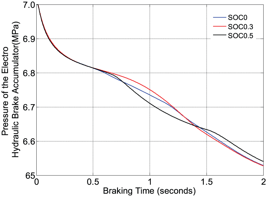
Pressure change of the hydraulic brake accumulator.

Energy recovery efficiency.
As can be observed in the simulation results, the SOC of the regenerative braking accumulator has a significant effect on the regenerative braking accumulator pressure and energy recovery efficiency, but a light effect on the pressure change rate.
Figure 18 shows increasing energy recovery efficiency with the initial SOC, but the energy recovery efficiency is decreased when the SOC of the regenerative braking accumulator exceeds a certain value. Therefore, it is necessary to make a reasonable choice of the initial SOC and the capacity of the regenerative braking accumulator to obtain the high performance; this is essential to develop a more efficient control method.
In a word, the liquid capacity and the initial SOC of the regenerative braking accumulator are key factors that affect the recovery efficiency, and the initial braking speed is the key point that influences the total energy recovery. The liquid capacity and the initial SOC should be consideration in cooperative and the efficient energy recovery will be obtained.
Conclusion and forward
A novel structure of the combined braking system based on the regenerative braking energy has been proposed to achieve simplified structure and energy-saving capability simultaneously, which includes the hydraulic regenerative braking system, electro-hydraulic braking system, and the power coordinate module. The corresponding mathematic model is developed and a simple fuzzy control method is proposed to coordinate the power between the high-pressure and low-pressure accumulators. The correctness of the model is verified by comparing the results of the test bench. The dynamic characteristics and efficiency of this novel system are further investigated in various parameters. The simulation results show that the liquid capacity and initial SOC of the regenerative braking accumulator are the key factors that affect the energy recovery efficiency, and the initial braking speed is the key point that affects the total energy recovery. Currently, the simulation results obtained in this work would be validated experimentally in immediate future and may provide theoretical support to develop the efficient control algorithm of the hydraulic regenerative braking system.
Footnotes
Academic Editor: Nasim Ullah
Declaration of conflicting interests
The author(s) declared no potential conflicts of interest with respect to the research, authorship, and/or publication of this article.
Funding
The author(s) disclosed receipt of the following financial support for the research, authorship, and/or publication of this article: This research was partly supported by the Chinese National Natural Science Foundation (51078167), the Outstanding Talent Financing Plan of Beijing Municipal Party Committee Organization Department (2014000020124 G098), Science and technology program of Beijing Municipal Education Commission (KM201611232002), and Construction of Scientific Research Base Project of Beijing Municipal Education Commission (PXM2016_014224_000004).