
Abstract
This article proposes multiple hinges’ type spectrum that provides an effective description of the multiple hinges of planar kinematic chains. The relationships between characteristic invariants are established and applied into type synthesis methods. A type synthesis method for planar kinematic chains, which is called the characteristic spectrum analysis type synthesis method, is proposed. A systematic design method for variable camber mechanisms is proposed. Using the results of the type synthesis and the systematic design method, three design schemes are proposed and the mathematic models are set up. Some simulation analysis has been done. All these analyses can verify the deformation performance of the proposed mechanism.
Keywords
Introduction
A variable camber mechanism is one such mechanism that can change its camber. It can form different degrees of curvature. It has many applications of advanced engineering machinery such as mechanical arms, deployable mechanisms, and morphing wings. A morphing wing1–4 can change its camber using variable camber mechanism as shown in Figure 1. The mechanism creates a camber that improves the aerodynamic characteristics of an aircraft, increasing the lift coefficient from 0.08 to 0.4 for a civil airplane wing. 5 The mechanism reduces fuel consumption by 5%, thus saving US$7 billion a year for American commercial jets. 3 It can also improve the maneuverability of fighter aircrafts. Thus, the study of variable camber mechanisms has very important scientific and real-world significance.
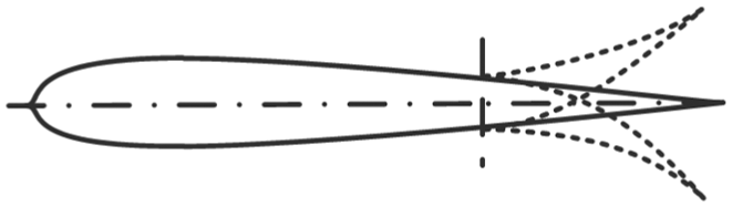
A morphing wing mechanism.
U.S. Air Force and NASA proposed a plan called “mission adaptive wing.” 6 An AFTI/F-111 airplane was used as a prototype which had a morphing wing. There is one morphing leading edge and one morphing trailing edge on each of its wings. But the structure is complex and the weight of the morphing wing is too heavy. Based on the achievements, U.S. Department of Defense proposed another plan called “smart wing.” 7 Shape memory alloy (SMA) torque tubes are put into wings. However, the torsion angle of the wing tip can only get 1.25°. The scholar DLR H. Monner proposed a morphing wing which was made up of flexible ribs.5,8,9 The whole structure is 1 degree of freedom (DOF). It can achieve continuous camber changing. But there are some prismatic pairs in the flexible ribs which may be jammed in practical application. University of Virginia developed a morphing wing using SMA. 10 The mechanism is made up of many basic loops, which connect each other by revolute pairs. SMA is put between loops to drive the whole mechanism. Therefore, the DOF of the whole structure is not 1. The whole mechanism is heavy. In 2011, Kansas State University successfully applied pressure adaptive honeycomb structure to morphing wings. 11 But the deformation effect is not ideal. Many of the studies about variable camber mechanisms focus on intelligent material. However, the reliability of variable camber mechanisms which use intelligent material is not high. There is also not a systematical design method for variable camber mechanisms.
Before proposing systematical design method for variable camber mechanisms, it is necessary to do type synthesis for planar linkages. Most of the current researches on the type synthesis of planar kinematic chains focus on planar single hinges. However, in the application of variable camber mechanisms, multiple hinges serve as important joints for variable camber mechanisms.
There are fewer type synthesis methods for planar kinematic chains which include both planar single- and multi-hinges. Many of them will cost large time to do isomorphic judging. Davies and Crossley 12 introduced the point interpolation method for analyzing the topology of embryo figures. This method, however, creates many isomorphic and unreasonable chains. Manolescu and colleagues13,14 proposed the binary linkages’ transformation method, which obtains all the structures through the derivation of the kinematic chain. The disadvantage lies in the significant work required by isomorphic judging. Tuttle’s 15 theory of finite groups facilitates the confirmation of the numbers and types of the parts in the kinematic chain to determine the relationships between the parts. However, this method is complex, difficult to master, and also involves extensive isomorphic judging. Rao developed a kinematic chain synthesis method using hamming number technique. This method also costs much time on isomorphic judging. 16 The methods above all need to spend much time on isomorphic judging and are not fit for planar kinematic chains including both planar single- and multi-hinges. Jinkui and Weiqing 17 proposed the weighted double-colored contracted graph method for 10-bar,1-DOF linkages with multi-hinges. Although it can analyze kinematic chains with multi-hinges, the method is not intuitionistic and requires complex isomorphic judging. In 2001, Rao and Deshmukh 18 proposed the basic loop synthesis method. It is intuitive, but it is not convenient to judge isomorphic. Song proposed a combination method of type synthesis for planar kinematic chains with both single- and multi-hinges.19–21 However, this method will bring negative sub-chains which will make the method complex. In 2011 and 2012, Huafeng et al.22,23 proposed computer-aided synthesis method based on the loop algebra theory. However, this method can just apply on kinematic chains without multi-hinges.
Li and Jian
24
proposed a characteristic spectrum classification method to classify the planar kinematic chains, which can effectively reduce the isomorphic judging requirements. There are five characteristic invariant spectrums in the classification method: degree spectrum D, order spectrum R, multi-hinge spectrum C, hinge spectrum for multiple-order linkage Jj, and prismatic joint spectrum for multiple-order linkages

Planar kinematic chain.
However, this method can only be used to classify planar kinematic chains, not for type synthesis. This article will propose a multi-hinges’ type spectrum and a novel type synthesis method based on the classification method proposed in Li and Jian. 24
The objective of this article is to design morphing wing mechanisms using planar linkage mechanisms that consider multiple hinges. The remainder of this article is organized as follows. Section “A novel type synthesis method for planar kinematic chains” presents the concept for the multi-hinges’ type spectrum for planar kinematic chains. By applying characteristic invariant spectrums, a novel type synthesis method for planar kinematic chains is proposed. A systematic design method for morphing wing mechanisms is proposed in section “Design of variable camber mechanisms.” Based on the results of type synthesis and the proposed systematic design method, three morphing wing mechanisms are presented. Mathematical models and kinematic simulations are conducted, followed by the conclusion in the final section.
A novel type synthesis method for planar kinematic chains
Definition of type spectrum of multiple hinges for planar kinematic chains
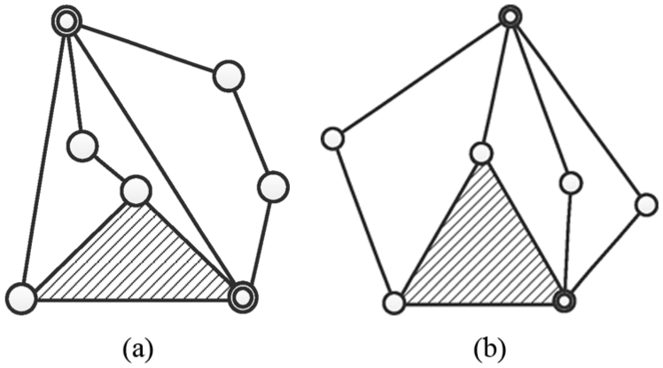
The multi-hinges’ type spectrum for planar kinematic chains, represented by CT, provides an accurate description of multi-hinges. In Figure 3, there are two different multi-hinges that connect with three bars. To describe multi-hinges more clearly, the following expression is proposed

where

Component situations for multi-hinges: (a) multi-hinge
In Figure 3, multi-hinge

There are two multi-hinges for the planar kinematic chain in Figure 4: one two-multiplicity multi-hinge and one three-multiplicity multi-hinge. Thus, CT can be represented as


Different connecting configurations for the planar kinematic chain: (a) the components of the kinematic chain, (b) the first configuration, and (c) the second configuration.
Based on the above definition, D can be determined by R, C, and CT. Then, all six characteristic invariant spectrums can be achieved. For example, there is a1-DOF 8-bar closed-loop planar kinematic chain with both single- and multi-hinges whose R = {1, 7}, C = {1, 1, 5}, and CT = {1-3M-2222, 1-2M-223}. Accordingly, the kinematic chain comprises the parts shown in Figure 4(a). An analysis of the connections reveals that there are only two possibilities, as shown in Figure 4(b) and (c).
For Figure 4(b), part one and part two are connected by one bar and two multi-hinges. For Figure 4(c), part one and part two are connected by one bar, one multi-hinge, and one single hinge. The remaining parts can then be put into the two configurations to create whole kinematic chains, as shown in Figure 5.
Two kinematic chains: (a) the first kinematic chain and (b) the second kinematic chain.
Then D can be determined based on the kinematic chains in Figure 5. For Figure 5(a), D is {1, 4, 1, 2}, and for Figure 5(b), D is {5, 2, 1}. Hence, CT is the bridge between R, C, and D. It also plays a very important role in the characteristic spectrum analysis type synthesis method proposed herein.
A novel type synthesis method with characteristic spectrum analysis
Type synthesis methods based on mathematics are precise, but difficult to master. In contrast, methods based on graph theory are easy to understand, but they also tend to lose possible situations. A method using both mathematics and graph theory would be ideal. Hence, this article proposes a novel method using characteristic invariant spectrums and mathematics. The most important advantage of this method is the application of the characteristic spectrum classification method, which has been proven to be fit for kinematic chains with both single- and multi-hinges and effectively reduces isomorphic judging requirements. 24
Novel type synthesis method
For a certain planar mechanism, the freedom F can be calculated by the number of parts N and the number of equivalent kinematic pairs J

Meanwhile, the equivalent kinematic pairs transform all the multi-hinges into single hinges. For example, a two-multiplicity multi-hinge is equivalent to two single hinges.
25
A multi-hinge factor was proposed to describe the relationship between the number of parts and equivalent joints.
26

Based on the above formula, the range of

where
Using the above results, C can be obtained.
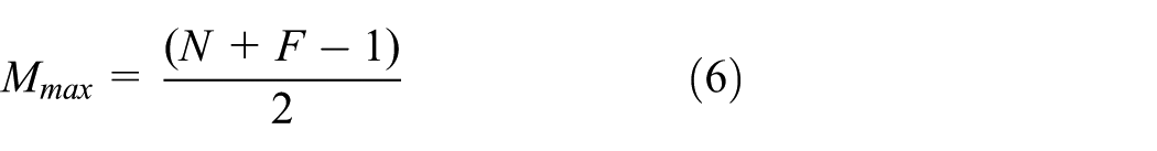
Then the number of bars with different orders

where
R and C can be obtained using the above results. Then this article can create CT. The creating process is shown in section “Definition of type spectrum of multiple hinges for planar kinematic chains.”CT can make sure the possible connection situations of kinematic chains. It is the base for the following work. Without CT results, D cannot be determined. CT is the bridge between R, C and D. Therefore, CT plays a significant role in this method.
Based on the CT results and the relationships between single- and multi-hinges,
25
when two single hinges turn into one two-multiplicity multi-hinge, three two-degree bars turn into three three-degree bars, and the chain links increase by

Based on Euler’s theorem, 28 if there are y edges and x vertexes, the number of independent loops is

To avoid rigid kinematic chains, there must be at least four bars in one planar kinematic chain.

The following equations are based on the relationship between chain links and degree

where
The solution for equation (11) only satisfies the mathematical relationship. It may not satisfy the kinematic relationship. Thus, the solution is just the possible value. To determine D, the kinematic chains need to be drawn using the above results and then classified by characteristic spectrums to delete isomorphic kinematic chains. The process is shown in Figure 6.
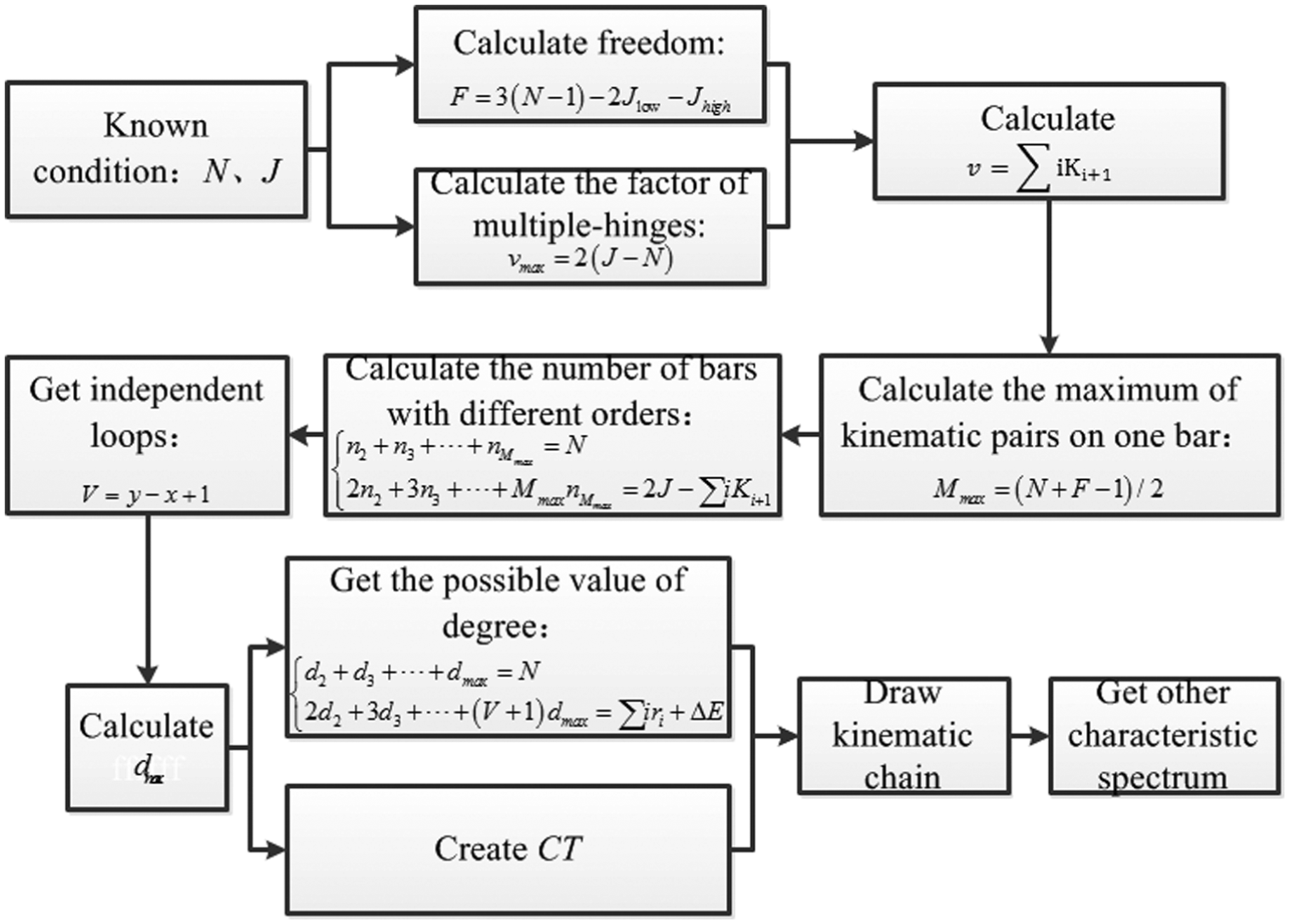
Process of type synthesis of characteristic spectrum analysis.
Illustrative examples
Based on Figure 6, this article conducts type synthesis on seven- and eight-bar mechanisms. The results of the seven-bar mechanism are shown in Table 1. There are four kinds of kinematic chains without multi-hinges and five with multi-hinges.
Two-DOF planar closed kinematic chain for seven bars with multi-hinges.

The results of the eight-bar mechanism are shown in Table 2. There are 16 kinds of kinematic chains without multi-hinges and 44 with multi-hinges. The results of the eight-bar mechanism confirm the findings of other scholars.27,29
One-DOF planar closed kinematic chain for eight bars with multiple hinges.

Design of variable camber mechanisms
Systematic design method for variable camber mechanisms
Many scholars have studied variable camber mechanisms and proposed design schemes that focus on new intelligent materials or traditional materials with multi-stage drives. If one variable camber mechanism has more than one drive, the weight and the possibility of malfunction will increase. Thus, the fewer drives the better.
If the variable camber mechanism is intended to change its camber continuously, there must be more than two closed loops. To avoid a rigid chain, there must be more than three bars in one independent closed loop, as shown in Figure 7. Thus, there should be not less than seven bars in one mechanism.

Mechanism with two closed loops.
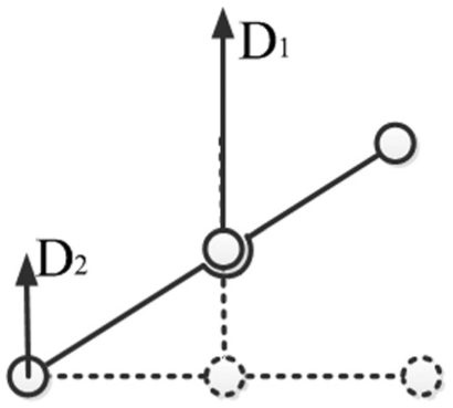
Because there are no high pairs in the mechanisms, the number of parts in the kinematic chain must be even to ensure that the mechanism’s DOF is 1. Hence, the starting point must be a planar 8-bar mechanism, followed by a 10-bar mechanism, and so on. A typical planar structure is shown in Figure 8(a), comprising two bars and three hinges. It has two important characteristics. First, if there is an input on one side of the horizontal bar when the middle bar is fixed, there will be an opposite output as shown in Figure 8(b). Second, if there is an input to the middle bar when one side of the horizontal bar is fixed, there will be an orthokinetic and amplifying output, as shown in Figure 8(c).

Characteristics of the teeterboard mechanism: (a) the teeterboard mechanism, (b) opposite output, and (c) orthokinetic and amplifying output.
Because of the two characteristics, this mechanism is taken as a basic unit in this article. In this article, the units in Figure 8(b) and (c) are called the direction translation unit and the displacement amplifying unit. For variable camber mechanisms, the deformation of the back unit must be larger than the front. Then, a camber can be formed. Based on the previous analysis, the examination begins with eight-bar mechanisms.
When there is no fixed endpoint in a displacement amplifying unit, the same effect also can be obtained, if the middle bar has a larger displacement than the “fixed” endpoint, as shown in Figure 9.
Displacement amplifying unit.
In Figure 9, there is no fixed endpoint.
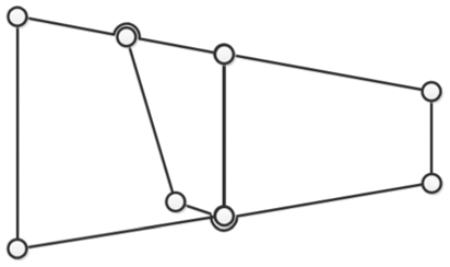
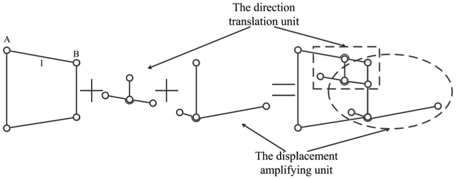
In Figure 10, the first left-hand unit can provide two different displacement inputs. Endpoint A is fixed. When the variable camber mechanism changes its camber, bar 1 rotates around A. This gives B the maximum vertical displacement among all the points on the bar. Hence, B connects with the middle bar of the displacement amplifying unit to provide a larger input. The second left-hand unit is the displacement amplifying unit. To make the shape of the mechanism look like a wedge, there is a transformation. Then, bars are used to create the mechanism, as shown in Figure 11.

Design process of a variable camber mechanism.
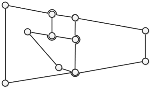
Design scheme for a variable camber mechanism.
Based on Figure 11, when the drive provides an angle input for bar 1, the deformation of the second closed loop exceeds the first, forming a camber. If the camber is expected to change more continuously, the mechanism must involve more closed loops, as shown in Figure 12.

Design scheme for a variable camber mechanism with three closed loops: (a) the design process for a variable camber mechanism and (b) one design scheme for a variable camber mechanism with three closed loops.
By the same principle, another scheme can be designed as shown in Figure 13.

Design process for a variable camber mechanism.
The whole design scheme for the variable camber mechanism is shown in Figure 14.

One design scheme for a variable camber mechanism.
A mechanism with more modules is shown in Figure 15.

Design scheme for a variable camber mechanism with three closed loops: (a) the design process for a variable camber mechanism and (b) one design scheme for a variable camber mechanism with three closed loops.
The design schemes above only use displacement amplifying units. The design process can also use both direction translation and displacement amplifying units. The function of the former is to change the input direction to obtain an opposite output. It can serve as the fixed point of the displacement amplifying unit. Based on this ideology, the design process is shown below.
In Figure 16, when bar 1 rotates around A counter-clockwise, B provides an upward input to the right side of the direction translation unit and the middle bar of the displacement amplifying unit. The left side of the direction translation unit then has a downward output. The downward output is given to the fixed point of the displacement amplifying unit. The whole mechanism is shown in Figure 17.
Design scheme for a variable camber mechanism with two kinds of basic units.
One design scheme for a variable camber mechanism.
The number of closed loops can be increased, as shown in Figures 12 and 15. Based on the above ideology, the basic units can be arranged in series to systematically design variable camber mechanisms.
The benefit of increasing direction translation units is that when the number of direction translation units is increased, their final output is amplified. Then, the input for the fixed point is larger than the initial input, which results in a more obvious change in the camber. Thus, designers can systematically design variable camber mechanisms.
Mathematical models for the design schemes
Based on the results from the eight-bar mechanism and the systematic design method for the variable camber mechanisms, this article selects three different kinematic chains to design variable camber mechanisms. The proposed three design schemes are shown in Table 3.
Design schemes for variable camber mechanisms.

To fulfill the general condition, this article also conducts modularized assemblies. The modularized assembly figures for the subsequent schemes are shown in Figure 18.
Design scheme with three modules: (a) the first scheme, (b) the second scheme, and (c) the third scheme.
The mechanism in Figure 18 all use bars and the DOF of each mechanism is 1. So the whole mechanism only needs one driver. When these mechanisms are applied to morphing wings, the driver will be fixed on the wing box, rather than on the variable camber mechanism. It will have lighter weight than the mechanisms in Monner et al., 5 Hardy, 6 Munday and Jacob, 8 Monner, 9 and Elzey et al. 10 To compare with the mechanism in Hardy, 6 the structure of the morphing wing is complex. There are so many parts in their mechanism which can be found in the figures in Hardy. 6 For the same size of the variable camber mechanism, it is obvious that the proposed mechanism in this article has lighter weight. For Monner et al., 5 Munday and Jacob, 8 and Monner, 9 their mechanism uses plates to design variable camber mechanisms. In each unit, there are three plates which can be found in figures in Monner et al., 5 Munday and Jacob, 8 and Monner. 9 So when the size of the variable camber mechanism and the number of basic units are same, the weight of the proposed variable camber mechanism in this article is lighter. For Elzey et al., 10 their mechanism is driven by SMA. So there are many SMAs between each basic loop. When the mechanism changes its shape, SMA will move with the variable camber mechanism. The variable camber mechanism proposed in this article uses only one motor to drive. The driver can be fixed on the wing box. So when the variable camber mechanism changes its shape, the driver will not move with the mechanism. Therefore, for the same size of the variable camber mechanism, the weight of the proposed mechanism in this article is lighter.
Mathematical model for the first design scheme
As shown in Figure 19, it is assumed that the angle between BD and

Variable camber mechanism with multi-hinges.
The known conditions:


The median lines of ABDC, CDGH, and HGKL can be calculated as


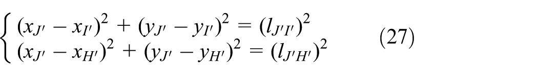
The length of EF and IJ can be obtained by the following equations


Based on the results of the above equations, the coordinates of A, B,


Hence


The coordinates of H are

The coordinates of


Finally, the relationship between the initial and equivalent angles can be set up

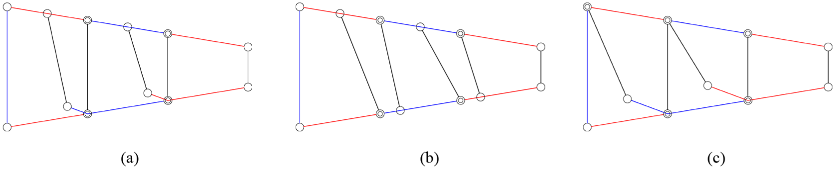
The results of the kinematic simulation in MATLAB are shown in Figure 20.

Kinematic trajectory simulation results from MATLAB: (a) the trajectory diagram and (b) the midline diagram.
For the first design scheme, the initial inputs are
Mathematical model for the second and third design schemes
The process of setting up the last two mathematical models is the same as the first one. The results of the kinematic trajectory simulation are shown in Figure 21.

Mathematical models and kinematic trajectory simulation results: (a) the second design scheme, (b) the third design scheme, (c) the simulation result of the second design scheme, and (d) the simulation result of the third design scheme.
For the second and the third design schemes, the initial inputs are
Three-dimensional models and ADAMS simulation results of the variable camber mechanisms
To better understand the design schemes, three-dimensional (3D) models are prepared as shown in Figure 22.

3D models of the design schemes for the variable camber mechanisms: (a) 3D model of the first design scheme, (b) 3D model of the second design scheme, and (c) 3D model of the third design scheme.
Then 3D models are put into ADAMS for kinematic simulation. The angular velocity of the motor is
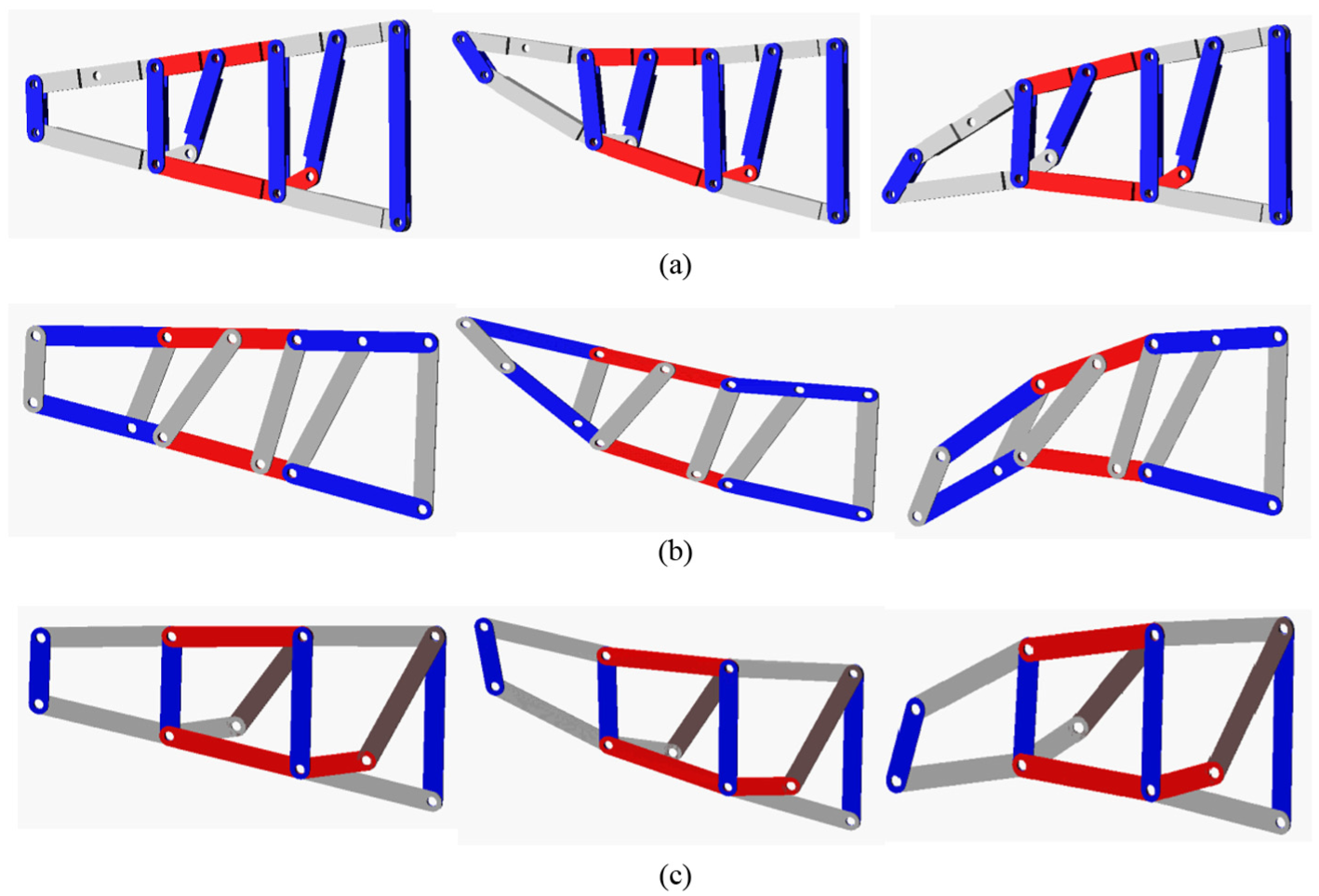
Kinematic simulation results in ADAMS: (a) Scheme A, (b) Scheme B, and (c) Scheme C.
The kinematic simulation results obtained by ADAMS are the same as the results obtained by MATLAB. The final outputs of the three design schemes are from
When a morphing wing has different shapes, it is fit for different fly conditions. For example, when an airplane takes off, it needs large lift force. The equivalent angle of the morphing wing should be biggest. When an airplane cruises, the equivalent angle should be
By different numbers of the variable camber mechanisms, a morphing wing trailing edge can be set up. For example, four structures of the first design scheme are used to make a morphing wing trailing edge as shown in Figure 24.

Assembly diagram of Scheme A: (a) Front view and (b) top view.
There is only one driver. The driver will drive the lead screw. The nut on the lead screw will push or pull the cross-bar. Finally, the cross-bar will make the morphing mechanism change its camber.
Conclusion
This article proposes a multi-hinges’ type spectrum for planar kinematic chains. The relationships between other characteristic invariant spectrums are established. A type synthesis method for planar kinematic chains, called the type synthesis method of characteristic-spectrum analysis, is proposed. Planar seven- and eight-bar mechanisms are used to verify the proposed method and the results indicate that it performs well on the type synthesis of planar mechanisms. A method is proposed for the systematic design of variable camber mechanisms. The advantage of the proposed design method is that it can systematically design a class of variable camber mechanisms, rather than one camber morphing mechanism. It can improve design efficiency and help designers master different variable camber structures as soon as possible. Eight-bar type synthesis results and the systematic design method are then used to create three design schemes. The analysis of these design schemes indicates that they are capable of achieving gradual camber deformation. For future work, some more detailed analysis will be done such as aerodynamic analysis, structure parameters optimization, mechanical property analysis, morphing skin design, and control system design. A prototype will be under manufactory for experiment tests.
Footnotes
Academic Editor: Yangmin Li
Declaration of conflicting interests
The author(s) declared no potential conflicts of interest with respect to the research, authorship, and/or publication of this article.
Funding
The author(s) disclosed receipt of the following financial support for the research, authorship, and/or publication of this article: This work was supported by the National Natural Science Foundation of China (grant no. 51521003, 61573336); in part by Self-Planned Task (grant no. SKLRS201508B) of State Key Laboratory of Robotics and System (HIT) and in part by Science and Technology Project of Guangdong, China (grant no. 2016A010102004).