Abstract
The morphing wing with large deformation can benefit its flight performance a lot in different conditions. In this study, a variable camber morphing wing with compliant leading and trailing edges is designed by large-displacement compliant mechanisms. The compliant mechanisms are carried out by a hyperelastic structure topology optimization, based on a nonlinear meshless method. A laminated leading-edge skin is designed to fit the curvature changing phenomenon of the leading edge during deformation. A morphing wing demonstrator was manufactured to testify its deformation capability. Comparing to other variable camber morphing wings, the proposal can realize larger deflection of leading and trailing edges. The designed morphing wing shows great improvement in aerodynamic performance and enough strength to resist aerodynamic and structural loadings.
Keywords
Introduction
The conventional wings are usually designed for a certain flight condition of aircraft and thus are suboptimal under other requirements. While the morphing wings can reduce the design compromises in the traditional aircraft design. There is neither an exact definition nor an agreement about the title of “morphing wing.” The general perception of morphing is that of smooth and continuous shape change, flexibility, and the “art” of mimicking birds. 1 Through the function of morphing, the morphing wings are expected to obtain different aerodynamic performances efficiently according to their mission roles.
The comparison between the effectiveness of morphing wing aircraft and conventional fixed wing aircraft in different flight conditions is shown in Figure 1, based on the NextGen design. The morphing wing aircraft shows more potentials in different missions than the fixed wing aircraft. Besides, hinged mechanisms are used to change the flight performance in the traditional aircraft control system, such as the flaps and slats. These control systems make the wing surface discontinuous, and thus are effective in changing airflow but inefficient in the aerodynamics. 2 Also, the noise of fixed wings can be suppressed largely if continuous skins are covered on the slats and flaps. 3

Spider plot of comparison of fixed and morphing wing aircraft. 4
Many research studies have been carried out to analyze the aerodynamic characteristics of morphing wings. Burnazzi and Radespiel evaluated the aerodynamics of flexible droop noses, which can reduce the Coanda flap blowing power and increase the attack angle of maximum lift coefficient (Cl). 5 Jo et al. implemented an aerodynamic testing of a variable camber compliant wing by wind tunnel test, showing 4% lift improvement in takeoff condition and 15% induced drag reduction in cruise condition. 6 Wang et al. investigated the aerodynamic characteristics of leading-edge droop nose devices of A380 and A350 and found that the devices can reduce takeoff drag as well as noise emission. 7 The improvement in aerodynamic characteristics provides much of the impulsion for the design of morphing wings.
The morphing wing can be designed from many aspects, such as variable camber 8 –10 and variable thickness 11 of aerofoil-level morphing, variable sweep 12,13 of spanwise morphing, twist 14,15 and folding 16,17 of wing-level morphing. In the early stage, morphing wings were designed by complex rigid-body mechanisms and actuators. 18 –20 However, rigid-body solutions always accompanied penalties in terms of cost, complexity, or weight. Although the penalties may be overcome by benefits of morphing wings in some certain circumstances, the penalties prevent their practical application, 21 especially for the low-speed/small-shape aircraft. 22 Besides, the using of smart materials is also quite prevalent in the morphing wing design. 14,16 However, they offer limited potential at the current state, due to limited scalability, force-deflection characteristics, and required power. 1 Compliant mechanisms, transferring force and displacement through elastic body deformation, own many benefits, such as ease of manufacture and assembling, no backlash, lightweight, and so on. 23 Thus, many researchers introduced the compliant mechanisms in the morphing wing design, especially in the variable camber wing with deflectable leading and trailing edges. 24 –26
FlexSys Inc (2205 Commonwealth Blvd, Ann Arbor, MI, USA). 25 developed a “Mission Adaptive Compliant Wing” (MACWing), owning a compliant mechanism-based trailing edge which is designed by continuum material topology optimization method. Its trailing edge can realize ±10° flap deflection with a 3° twist. Taking the whole airfoil as the design area, Santer and Pellegrino 27 designed a compliant mechanism-based morphing wing by load path-based topology optimization method. Similarly, Maute and Reich 21 designed the morphing wing in the whole airfoil by material-based compliant mechanism topology optimization, within a coupled fluid–structure analysis framework to directly assess aerodynamic performance criteria. Xin et al. 28 proposed a material-based nonlinear topology optimization method for the leading edge, and Xinxing et al. 9 introduced the composite materials into the leading-edge compliant mechanism design. German Aerospace Center presented a droop-nose adaptive morphing wingtip by compliant mechanism for the European FP7 project “Novel Air Vehicle Configurations: From Fluttering Wings to Morphing Flight.” 24 In the same European project, Politecnico di Milano (POLIMI) 29 designed both leading and trailing edges by load path-based compliant mechanism design method. The US Air Force Research Laboratory (AFRL) 6 also designed a “Variable Camber Compliant Wing” (VCCW) with both compliant leading and trailing edges with only one single actuation, and its design can actively recontour the airfoil camber up to 6%. Diaconu et al. 30 developed a bistable compliant mechanism-based trailing edge by bistable laminated composite structures design method. However, only two stable shapes can be realized. Ricci et al. 31 investigated the configuration of skin and internal compliant mechanisms by a load path-based multi-objective optimization simultaneously.
However, the deflection of compliant mechanism-based leading and trailing edges are usually small, due to the fact that the adopted compliant mechanisms were designed by linear design methods and manufactured by linear-elastic materials with high stiffness. That means the morphing wings will profit less from its morphing. Hence, the design of nonlinear compliant mechanisms with large displacement is necessary.
One of the widely used compliant mechanism design methods is topology optimization, 32,33 and nonlinear topology optimizations of large deformation problem have been studied by a lot of researchers. 34,35 Besides, meshless methods, which are quite suitable for large displacement problem, are introduced to replace the finite element (FE) response analysis in topology optimization. Cho and Kwak introduced the geometric nonlinearity into the meshless-based topology optimization. 36 And then compliant mechanisms were designed by meshless-based topology optimization in many research studies. 37 –39 Considering the high computational cost, Zhang et al. replaced the costly meshless method by FE meshless coupled method in topology optimization. 40,41 In addition, the hyperelastic material, which is more suitable for the large deformation compliant mechanism design, is also introduced in the meshless-based topology optimization. 42
Hence, in this article, a meshless-based topology optimization method for hyperelastic structures is adopted to design compliant mechanisms of the morphing wing for a micro air vehicle (MAV). The MAVs usually fly slow and need high maneuverability, which means they can benefit a lot from the morphing wing. Compared to supersonic aircraft, the small or low-speed planes require more dramatic wing variations for a noticeable and practical change in their aerodynamic properties. 22 And considering the low bearing capacity of compliant mechanisms, the wing only needs to bear small aerodynamic load just as well. The hyperelastic structure-based compliant mechanisms are designed for both leading and trailing edges. A laminated skin is introduced to meet the leading-edge curvature changing requirement during the leading-edge deflection. A preliminary demonstrator is manufactured and its deformation capability is tested. At last, the aerodynamic performance is evaluated by simulation as well as the aerodynamic loads bearing capability.
Variable camber designs of leading and trailing edges
The airfoil curves are shown in Figure 2, in which the original airfoil curve before deformation shows as the solid line and the target morphed airfoil curve after deformation shows as the dashed line. Note that, although the target morphed airfoil is the only and final design object, there are various airfoils that can be achieved during the deformation and that riches the flight performance of the morphing wing.

Original airfoil curve and target morphed airfoil curve.
The morphing wing mainly includes two parts: skin and compliant mechanism. The skin is the reflection of the morphing, while the compliant mechanism is used to actuate the skin (transmitting the force from actuator to skin). Therefore, the design process of the variable camber morphing wing includes three steps:
Firstly, design the skin of the leading and trailing edges. The curvature of leading edge changes during the wing deforming, as shown in Figure 2. If the wing skin is processed to the original shape beforehand, the skin which has maximum curvature can be hardly reshaped to another different curve with only external loads applying to the skin, such as the design in the literature. 24,43,44 Hence, a laminated leading-edge skin is designed, as introduced in Appendix 1. The laminated skin, composed of spring steel and glass fiber-reinforced polymer composites, shows great advantages in dealing with the curvature changing phenomenon.
Secondly, optimize the driving forces of the skins. The deformation of the skin is actuated by the driving forces of the skin, namely, the output of compliant mechanisms. The driving forces need to conform to the skin deformation and meanwhile resist the aerodynamic loads. Hence, more driving forces work better. However, too many outputs may lead to the failure of the optimization of compliant mechanisms. Hence, two outputs of compliant mechanisms are adopted to actuate the skin deformation here. And then a driving forces optimization is needed to find the optimal parameters for the skins, including the position, value, direction, and displacement of the driving forces. The optimization is carried out by a genetic algorithm (GA) with the response analysis calculated by ANSYS, shown in the flowchart of Figure 3A in Appendix 3.

Schematic diagram of leading-edge design: (a) forces for driving leading-edge skin and (b) design conditions of compliance mechanism of leading edge.
Thirdly, design the compliant mechanisms to actuate the leading and trailing skins. By the parameters of the driving forces from the second step, the compliant mechanisms are optimized by a meshless-based topology optimization method for hyperelastic structure. The flowchart of the method is given in Figure 3B in Appendix 3, and the mathematical model is introduced in the next section.
Meshless-based topology optimization method for hyperelastic structure
Topology optimization is one of the most flexible structure optimization methods by optimizing the material layout in a specified design region. In this study, the compliant mechanism is optimized by the topology optimization based on the solid isotropic material with penalization (SIMP) method. To satisfy the requirement of large deformation, the hyperelastic structure is adopted in the topology optimization, using nonlinear meshless response analysis. In the SIMP method, the configuration is presented by the material density


where χ
i
is the material constant of hyperelastic material,

where ρi
is the nodal density and ϕi
is a Shepard function satisfying that
The objective function is to maximize the weighted summation of the two output displacements. Considering the nodal density as the design variable and material volume constraint, the optimization problem is stated as

where ρi
is the nodal density variable of the ith node; n is the total number of the both FE and element-free Galerkin nodes; C is the objective function;

ρ min is a lower bound of density which is set ρ min = 0.001 in here.
Sensitivity analysis
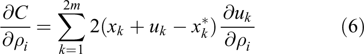
There are 2m degrees of freedom of the output ports, hence the sensitivity of the objective function can be given as
in which the displacement uk
of a specified degree of freedom k, and it can be written as
where

where

In the nonlinear analysis, the structural equilibrium is solved by Newton–Raphson method in this article, in which requires the determination of the tangent stiffness matrix

Letting the

The
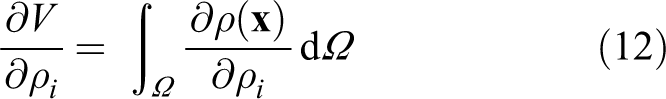
The derivative of material volume with respect to the design variables reads
In this study, the topology optimization of the compliant mechanism design is solved by the method of moving asymptotes (MMA). 46
Meshless method for hyperelastic structure
In the nonlinear hyperelastic meshless method, the governing equations in terms of the principle of virtual work state that

where
equation (4) can be reducible to a linear equations system by the incremental Newton–Raphson method


where
When the structure is undergoing large deformation, the low-density areas may excessively distorted, and their tangent stiffness may lose positive definiteness in the incremental nonlinear analysis. These numerical instabilities would stop the density-based topology optimization iteration. Replacing the nonlinear analysis of the low-density area by linear analysis is a simple and efficient method, 48 due to the fact that the sensitivity in low-density area would be suppressed largely by low-density, especially when considering the penalization (by a power function, usually taking power as 3) in SIMP method. Furthermore, the meshless method can be replaced by the linear FE method in the linear region, which also can save the computational cost of the expensive meshless method. Thus, an adaptive directly coupled FE and meshless method is introduced to reduce the computational cost of meshless methods, and an adaptive interpolation scheme is adopted to arrange FE and meshless domains during the optimization. For more details, please refer to Zhang et al. 42
Compliant mechanism for leading edge
The compliant mechanism is used to actuate the skin, transmitting the force of actuator to the skin. For the leading edge, considering that the compliant mechanism needs to conform to the skin deformation and meanwhile resist the aerodynamic loads, two outputs are adopted in the compliant mechanism design, shown in Figure 3(a).
The compliant mechanism topology optimization model of the leading edge is shown in Figure 3(b). Note that, there is no need to consider the resistance of skin in the compliant mechanism design, as the skin is actually simulated by the springs at the output ports. Hence, the skin area is excluded from the design domain (the gray area). The compliant mechanism is fastened to the bottom of the middle wing, shown as the displacement boundary fixed to the lower right of the design region. The input actuation force F in is applied horizontally to the left. The larger the distance between the actuation force and the displacement boundary is, the smaller the input actuation force would be needed. However, when setting the actuation force far away from the displacement boundary, the drive mechanism may cause interference with the leading-edge skin during the deformation. Hence, the input actuation is set at the right edge, 68.52% of the right edge length from the displacement boundary.
The springs at the output ports, which are used to simulate the resistance from the skin, are actually the stiffness of the workpiece in Sigmund, 32 and it can be calculated by

where Fi
is the compliant mechanism output force (also the driving force of the skin) and
Parameters of topology optimization for leading-edge compliant mechanism design.

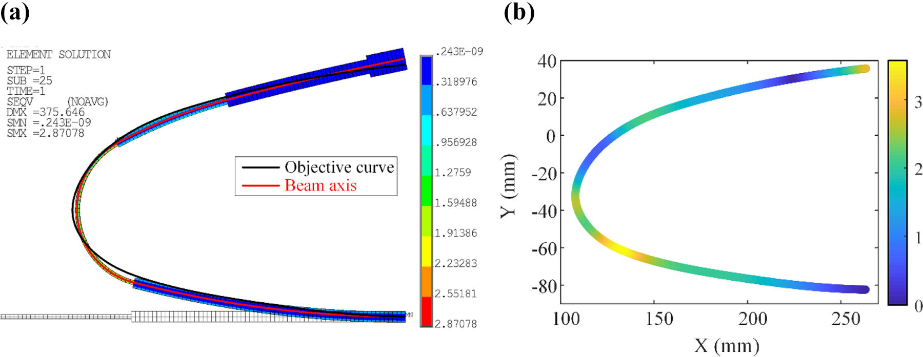
The deformation of the laminated leading-edge skin is given in Figure 4(a), and the error distribution is shown in Figure 4(b). The maximum error (3.32 mm) is at the forepart of the leading edge. Besides, the error at the upper end of the skin is also remarkable, as the leading-edge skin was deviated from the ideal initial curve after bending the laminated skin to the leading-edge curve.

Deformation of leading-edge skin: (a) deformed laminated skin driving by compliant mechanism output forces and (b) displacement error of the deformed leading-edge skin.
Considering a two-dimensional design area with thickness of 20 mm and the prescribed fraction of the volume constraint fV = 0.3, the topology optimization of the leading-edge compliant mechanism design is implemented according to the input and output parameters in Table 1. The optimal configuration of the leading-edge compliant mechanism is shown in Figure 4(a). The topology configuration is expressed by a density field, which includes a great deal of intermediate density. Hence, a post-processing program is needed. The density below 0.8 is deleted, and the minimum width is limited to 2 mm. A compliant pseudo-hinge is added to the bottom of the vertical bar which is connected to the upper skin, aiming for larger deformation. A computer-aided design (CAD) model is rebuilt and its deformation is shown in Figure 5(b), with von Mises stress displayed in the same figure.

Compliant mechanism designed for leading edge: (a) topology configuration of compliant mechanism and (b) deformation and von Mises stress of the deformed compliant mechanism.
Compliant mechanism for trailing edge
For the trailing edge, the skin is assembled by two straight spring-steel plates simply. To realize the variable camber design, the length of the lower skin should be reduced during the deformation, and the length of the upper skin should remain. Hence, the lower skin should be detached from the wing rib so that it can retreat to the middle wing in the deforming process, while the upper skin is fixed on the wing. Three forces are adopted here: two forces at the upper skin and one force at the lower skin, as shown in Figure 6(a). The two forces loaded at the upper skin are provided by the compliant mechanism. And the third force is located at the end of the lower skin, drawing the lower skin into the middle wing.

Schematic diagram of trailing-edge design: (a) forces for driving trailing-edge skin and (b) design conditions of compliance mechanism for trailing edge.
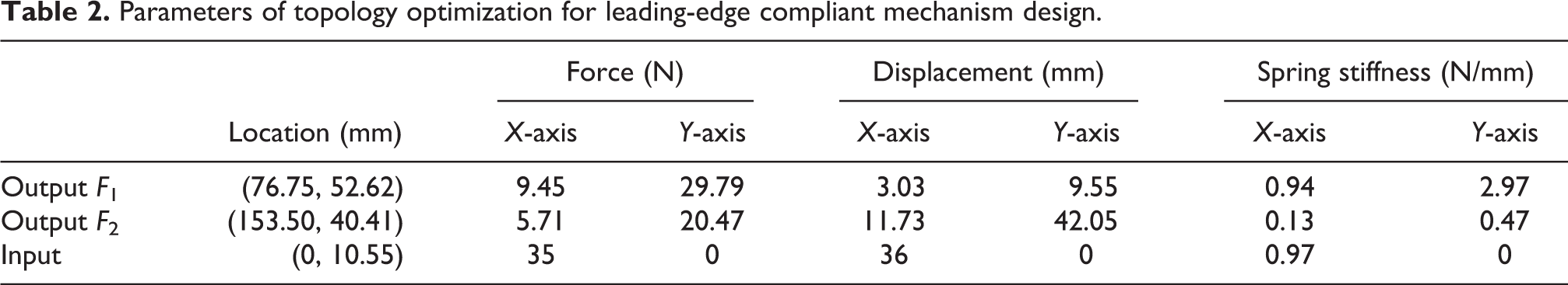
The same topology optimization method is adopted in the trailing-edge compliant mechanism design. The compliant mechanism is fastened to the top of the middle wing, shown as setting the displacement boundary to the upper left of the design region in Figure 6(b). To reduce the actuation load, the input actuation force is applied horizontally at the bottom on the left design region boundary. The output forces of the compliant mechanism are also optimized by the same method introduced in the “Compliant mechanism for leading-edge” section. The parameters of topology optimization are presented in Table 2.
Parameters of topology optimization for leading-edge compliant mechanism design.
The deformation of the trailing-edge skin is given in Figure 7, and the error distribution is also shown in the same figure. The deformed skin coincides with the target curve well, with the maximum error (6.07 mm) located at the tip of the trailing-edge skin.

Deformation of leading-edge skin driving by compliant mechanism output forces and its displacement error.
Considering the design area with thickness of 20 mm and the prescribed fraction of the volume constraint fV = 0.25, the topology optimization of the leading-edge compliant mechanism design is executed according to the parameters in Table 2. The optimal configuration of the leading-edge compliant mechanism is shown in Figure 8(a). The thin bar in the left side impedes the horizontal movement of the input actuation force. Besides, it is too far from the lower limit of the bar width (2 mm) mentioned above. Thus, it is deleted in the CAD model. The deformation and von Mises stress of the modified model is shown in Figure 8(b).

Compliant mechanism designed for trailing edge: (a) topology configuration of compliant mechanism and (b) deformation and von Mises stress of the deformed compliant mechanism.
Manufacturing and testing
CAD conceptual model
A morphing wing with 130-mm span is designed, with two same compliant mechanisms (10 mm thickness for each one) for the leading edge, and so does the trailing edge. The CAD conceptual model is displayed in Figure 9, including the deformed leading and trailing edges which are shown translucently.

CAD conceptual model of designed morphing wing.
In the variable camber leading edge, the skin and compliant mechanisms are connected by two stringers, which help to distribute the force from the mechanisms to the skin, displayed in Figure 10. Two compliant mechanisms are installed on both sides, with their input forces supplied by a shaft. The shaft is attached to a linear guide rail, ensuring that the input forces can be applied horizontally. The linear motion actuation is provided by a linear stepper motor through a leadscrew.

CAD conceptual model of the variable camber leading edge.
For the variable camber trailing edge, there are also two compliant mechanisms installed on both sides and connected with the skin by two stringers, as shown in Figure 11. A C-shape connector is designed to drive the two compliant mechanisms. The connector is attached to a linear guide rail and actuated by a stepper motor through a leadscrew.

CAD conceptual model of the variable camber trailing edge.
For the other input actuation force, which is applied to the lower skin, another drive mechanism is adopted. The skin is actuated by a leadscrew directly. Also, a linear guide rail is connected to the skin, making sure that the skin can move straightly along the lower skin of the middle wing.
Fabrication, actuation, and control
The monolithic compliant mechanisms were fabricated by three-dimentional (3-D) printing with flexible polylactic acid (PLA) material. The spring steel plate was fabricated by electrical discharge machining, and the glass fiber-reinforced polymer composites in laminated skin were fabricated using laser cutting. The compliant mechanisms and wing skin were fixed to a metallic perforated plate by some aluminum-fabricated connectors and 3-D printing pieces. The demonstrator is shown in Figure 12.

Demonstrator of the variable camber morphing wing and the displacement measurement system.
Three sets of actuation system are needed: one for the leading edge and two for the trailing edge. Each actuation system includes three parts: a motor to provide rotation movement, a leadscrew to convert the rotation movement to straight movement, and a linear guide rail to limit the motion path. In the trailing edge, the lower skin and the compliant mechanisms need to be actuated separately. And there is a relative sliding between the lower skin and the compliant mechanisms. Thus, two actuators are needed here: one for the two compliant mechanisms and one for the actuation of lower skin. Besides, two actuation systems can realize more precise control and more kinds of morphing shapes.
Note that, the morphing wing designed in this study is mainly for the deformation testing purpose. Hence, the actuation is provided by stop motor as its ease of operation. The static moment of the stepper motor is 0.12 N·M, and the lead of screw is chosen as 1 mm for larger transmission ratio. As the largest input force is 40 N (the leading edge), the motor can work at 0.08 N·M torque with 2200 pulse per second, according to the speed–torque characteristics of the step motor.
The control system includes an STM32 microcontroller (STMicroelectronics, Avenue Mohamed Jazouli Madinat AI Irfane, RABAT, Morocco) and three HST-8325B microstep drivers (HUISITONG No. 28, Chang’an Changba Road, Huishan District, Wuxi, Jiangsu, China) for each stepper motor, which is mounted inside the middle fuselage, between the two ribs. The input pulses of step drivers are provided by the pulse width modulation which is outputted by the STM32 microcontroller. The position is commanded to move and hold at one of these pulses (an open-loop controller). Hence, there is no position sensor for feedback in our actuation system, except four limit switches which are used to limit the travel of the motors.
Besides, in the demonstrator manufacturing, many standard parts are adopted for convenience, hence the weight of the demonstrator is overweight for the micro air vehicle. In the study of a compliant mechanism-based leading edge by FlexSys Inc. and AFRL, 25 its compliant mechanisms offer 22% decrease in weight over the current flap structure. Although its total weight increased 7%, mainly from the rotary actuation scheme, the wing morphing system can overcome the weight penalty well. The same benefits are expected in our design, due to that the wing is manufactured mainly by light composite materials and flexible PLA material, with only the outer skin of steel with 0.15 mm thickness. And the weight of the rotary actuation scheme can decrease by adopting more advanced actuation systems, such as the linear motors or smart materials. The actuation system upgrade and the weight reduction are important parts in our next work.
Displacements testing
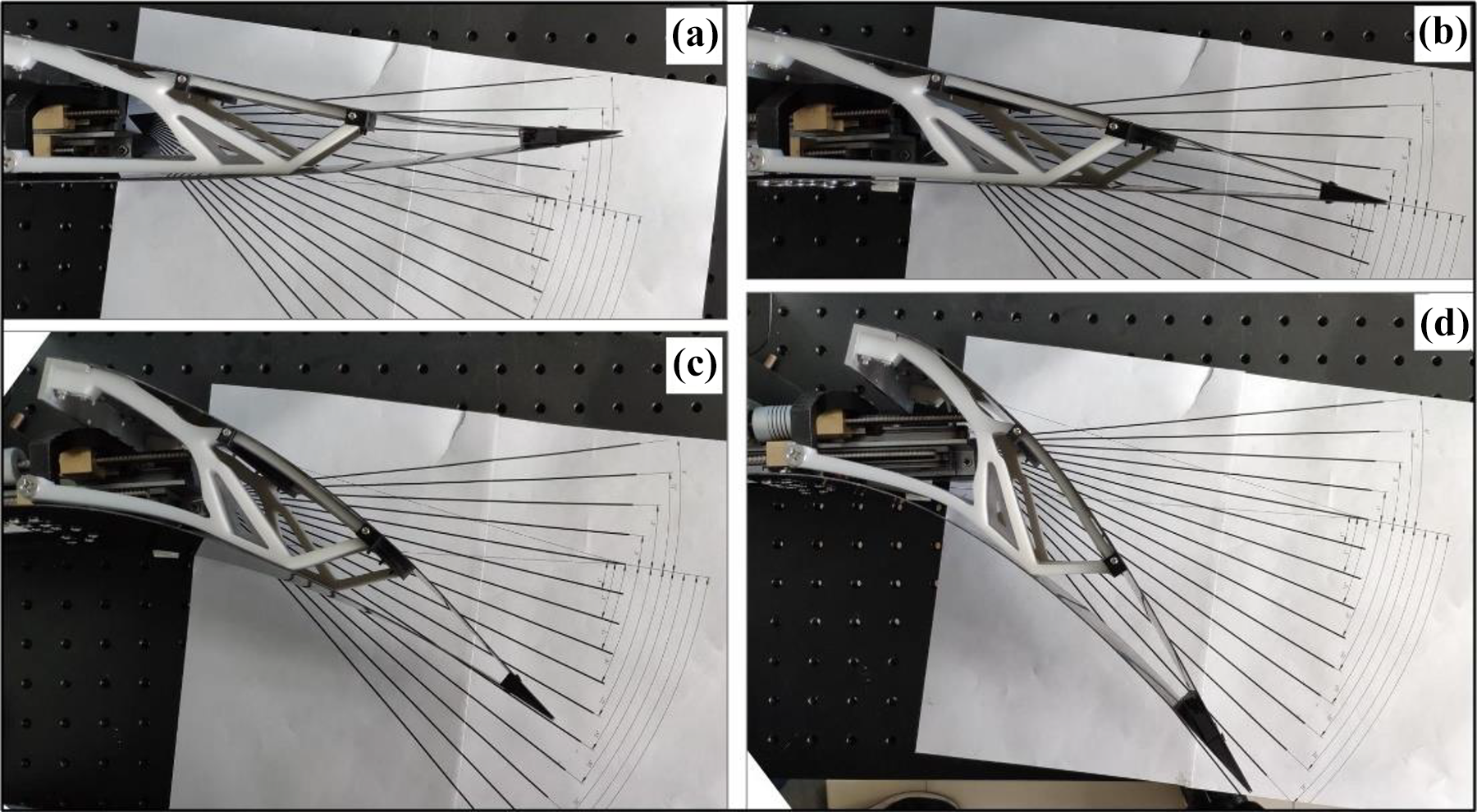
The deformation of the morphing wing was measured by a displacement measurement system, consisting of two orthogonal grating rulers and a laser for positioning, shown in Figure 12. The morphing leading edge with different deflection angles is displayed in Figure 13.

Deformation process of the leading edge. deflection angle of (a) 0°, (b) 18°, and (c) 27°.
For the leading edge, when the largest displacement actuation of 48 mm is actuated by the screw, the largest deflection angle can be up to 27°. The angle is defined by the deflection of a line, which line is connecting the minimum curvature point of the leading edge and the middle point of the interface between the leading edge and the middle wing. The deformation curves of four deflection angles (0°, 9°, 18°, and 27°) are shown in Figure 14 and plotted by the spline interpolation of the measured points. Considering the leading-edge skin is actually deviating from the initial curve, the deformation is almost identical with the target curve, with only a small difference around the leading-edge bottom. The partial enlarged drawing of leading-edge bottom part is also shown in Figure 14.

Measured deformation of leading edge under different deflection angles (0°–27°).
For the trailing edge, several typical deflections in the deformation process are displayed in Figure 15, including upward deflection in Figure 15(a) and downward deflection in Figure 15((c) and (d)). Noted that, though no upward deflection for trailing edge is considered in the design, the trailing edge can deflect upward by driving the compliant mechanism reversely.
Deformation process of the trailing edge: (a) upward deflection angle of 8°, (b) deflection angle of 0°, (c) downward deflection angle of 24°, and (d) downward deflection angle of 40°.
The measured deformation curves for the trailing edge with different deflection angles are shown in Figure 16. The deflection angle of trailing edge is defined by the line which is connected to the tip point of the trailing edge and the middle point of the interface between the trailing edge and the middle wing. The deflected curve coincides with the target curve quite well except the tip of the trailing edge, and the error coincides with the error distribution of the trailing-edge skin, as shown in Figure 7.

Measured deformation of trailing edge under different deflection angles (−8° to 40°).
Although the target is set to 24° downward deflection angle, the designed leading edge can deflect to a maximum of 40°, in which the input displacement of the compliant mechanism actuation is 38.73 mm and the lower skin actuation is 48.15 mm. For the upward deflection, the largest deflection angle is 8°, with the compliant mechanisms input displacement of −5.38 mm and the lower skin actuation input displacement of −9.74 mm.
Table 3 shows the comparison of the proposed wing with some typical variable camber morphing wings, which are presented here due to their large deformation properties. Note that, the deflection angles in other research are not all presented in their study, some of them are measured by the pictures in their article. The morphing wings in columns 1–9 are all designed by compliant mechanisms, in which the difference is the compliant mechanism design method they take. The wings in the last three columns are designed by other approaches, such as smart materials and rigid-body mechanisms. The proposed design owns the largest downward deflection in both leading- and trailing-edge design, and usually, the large deflection means the large change of the aerodynamic performance.
Note that the deflection angles in Table 3 are not all presented in their research articles, thus some of them are measured by the provided pictures. The regions of leading and trailing edge are defined as the region where the deformation occurs. And their deflection angles are defined as the same as the definition mentioned above.
Deflection comparison of the proposed wing over some typical variable camber morphing wings

Aerodynamic performance analysis
The aerodynamic performance of the morphing wing with deformed leading and trailing edges is analyzed by simulation in airfoil level here. Note that, although the morphing wing is designed by the compliant mechanisms, it can meet the aerodynamic load bearing capacity quite well in the design condition, shown in the “Aerodynamic load testing simulation” section. Hence, all the deformed airfoils are assumed to be rigid ones in the simulation, without considering the extra deformation due to the aerodynamic load.
The meshes of the camber deflection wing were generated by ANSYS ICEM (Ansys Inc./ANSYS 17.0), and the aerodynamic characteristics were evaluated by ANSYS Fluent (Ansys Inc./ANSYS 17.0). The standard k–ε model and SIMPLEC scheme (with standard pressure, least squares cell-based gradient, second-order upwind, first-order upwind turbulent kinetic energy, and first-order upwind turbulent dissipation rate) are used for the turbulence model and the solution method. Freestream velocity 80 m/s, air density 1.225 kg/m3, viscosity 1.7894 × 10⁻⁵
In the simulation, different attack angles are analyzed, from −20° to 20°. The deflection angle of leading edge changes from 0° to 27°, and the deflection angle of trailing edge changes from −8° to 40°. The simulation needs to repeat many times when analyzing the situations with different attack angles. Hence, codes by MATLAB are taken to generate the journal file of Fluent, then call the Fluent to execute the journal and save the results.
Figure 17 shows the development of pressure coefficient (Cp) of 12° attack angle versus leading-edge deflection angle and trailing-edge deflection angle. The deflection of leading and trailing edges can change the Cp distribution significantly. The deflection of leading edge mainly changes the load distribution around the leading edge, while the deflection of trailing edge changes the load distribution almost everywhere. And the conclusion is valid for other attack angle situations. Some fluctuations of Cp exist around Length/Chord = 0.2 in Figure 17(a) and Length/Chord = 0.9 in Figure 17(b), where the deflection starts.

Pressure coefficient (Cp) of the morphing wing. The Cp under different deflection angles of (a) leading edge and (b) trailing edge.
Aerodynamic analysis of leading-edge deflection
The Cl and drag coefficient (Cd) of the wing with variable leading-edge deflection under different attack angles are shown in Figure 18(a) and (b). The deflection of the leading edge has little effect on the Cl, especially when the attack angle is greater than −4° and less than 10°. When the attack angle is less than −4° or greater than 10°, the lift increases along with the deflection angle slightly, and the tendency is more distinct in the negative attack angle part.

Aerodynamic performances of morphing airfoil under different leading-edge deflection angles. (a) Lift coefficient (Cl), (b) drag coefficient (Cd), and (c) lift to drag ratio (Cl/Cd) of different attack angles.
The Cd decreases along with the attack angle in the negative attack angle part and increases in the positive part like a U-shaped curve. The leading-edge deflection shows higher impact on the Cd than the Cl. In the positive attack angle part, the Cd decreases along with the deflection angle, while in the negative part, the Cd increases along with the deflection angle.
The lift–drag ratio (Cl/Cd) is shown in Figure 18(c). The lift–drag ratios of each attack angles decrease at first, then increase in the middle and decrease at last, just like the sine curve. In the attack angle between −4° and 6°, the larger the deflection angle of the leading edge is, the lower the lift–drag ratio, and contrary in other angles. The non-deflecting leading edge owns the largest lift–drag ratio around zero attack angle, and the lowest lift–drag ratio is also at the non-deflecting situation at the attack angle of −10°.
Thus, for the takeoff phase in large attack angle, 27° deflection angle owns relative high lift and low drag. For high lift in the climbing phase, large attack angle and large deflection of leading edge should be taken. Non-deflecting leading-edge and zero attack angle are more suitable for the cruising phase, which owns the highest lift–drag ratio. In the plane descending phase in negative attack angle part, large deflection of leading edge can reduce lift and increase drag, and in the landing phase, large positive attack angle and large downward deflection of leading edge are more appropriate. Besides, non-deflecting of leading edge at −10° attack angle is more beneficial for the nosedive.
Aerodynamic analysis of trailing-edge deflection
The Cls of the wing with variable trailing-edge deflection under different attack angles are shown in Figure 19(a). The Cl increases along with the attack angle when the deflection angle is under 16°. When the deflection angle of trailing edge is larger than 16°, the increase of Cl may be stagnated along with the increase of attack angle, some even decreases. For example, the Cl of 40° deflection angle decreases in 4°–10° attack angle and then keeps steady roughly. The Cds of different camber trailing edges are U-shaped curves, with the attack angle of the lowest Cd decreasing gradually with deflection angle, as displayed in Figure 19(b).

Aerodynamic performances of morphing airfoil under different trailing-edge deflection angle. (a) Lift coefficient (Cl), (b) drag coefficient (Cd), (a) lift to drag ratio (Cl/Cd) of different attack angle.
The lift–drag ratios of different trailing-edge deflection angles are shown in Figure 19(c). For the deflection angle of −8° to 8°, there are three phases of the lift–drag ratios: decreasing at first, then increasing in the middle, and decreasing at last. For other deflection angles, the lift–drag ratios own only two phases: increasing in the first half and decreasing in the last half.
Thus, the trailing edge with 40° downward deflection in attack angle around 4° provides large lift and relative small drag, which is suitable for the takeoff phase. For the climbing phase, larger trailing-edge deflections are more applicable to the situation when attack angles are small (0°–8°), and smaller deflections are more appropriate when attack angles are large (8°–20°). Non-deflecting trailing-edge and zero attack angle are suitable for the cruising phase. In the plane descending phase, upward deflection of trailing edge can reduce lift and increase drag, and in the landing phase, large attack angle and large downward deflection of trailing edge owns the largest drag and relatively large lift.
Aerodynamic load testing simulation
Compared to the traditional wing, the designed compliant morphing wing is more flexible, and its aerodynamic load bearing capability is relative lower. Thus, a one-way fluid–structure interaction coupling method is used to investigate the aerodynamic load performance. This simulation is executed by ANSYS Workbench. Through APDL commands of ANSYS, the aerodynamic load is applied to the skin by the pressure load of Fluent.
In this modal, the span of the leading and trailing edges is 65 mm (half-width of the demonstrator in the “Manufacturing and testing” section), and the thickness of the compliant mechanism is 10 mm. The skin and compliant mechanism are connected by bonded contacts in Workbench (Ansys Inc./ANSYS 17.0). The fixed and actuated parts of the compliant mechanism are all fixed in the load bearing test, as well as the two ends of the up and down skins which are connected to the middle wing.
Noted that, the leading-edge skin is composed of a spring-steel plate (0.15 mm thickness) and several glass fiber plates. To simplify the simulation model, a 0.15-mm thick spring-steel plate is adopted to replace the leading-edge skin which is originally built by bent laminated skin with prestress inside. The Young’s modulus values are 206 GPa for the spring steel and 300 MPa for the flexible compliant mechanism material.
When taking the aerodynamic load of the wing in non-deflecting and zero attack angle situation, the deformations of leading and trailing edges are very small (the largest displacement is only 0.35 mm in leading edge and 0.18 mm in trailing edge), and so does the stress (largest von Mises stress is only 6.23 MPa in leading edge and 0.42MPa in trailing edge).
When considering the wing deflection, the largest variation of the aerodynamic load is close to five times during the deformation. Thus, five times aerodynamic load of the no deformation and zero attack angle situation is applied to the wing in simulation. The deformation and von Mises stress of fluid–structure interaction for leading edge are shown in Figure 20. In this situation, the largest displacement is 1.76 mm, and the von Mises stress is only 31.44 MPa in the leading edge. Besides, if considering the actual situation (several glass fiber plates sticking inside and prestress in the skin, and larger prestress after deformation), the deformation would be lower. Thus, comparing to the 175.20-mm chord length of leading edge and the yield strength of over 100 MPa of flexible material and 500 MPa of spring steel, the designed compliant leading edge can meet the aerodynamic load bearing capacity quite well in the design condition.

Deformation and von Mises Stress of fluid–structure interaction for leading edge.
For the trailing edge, actual geometric dimensions of the skin are set in the simulation. When five times aerodynamic load is applied, the largest deformation of trailing edge is only 0.91 mm (304-mm chord length of trailing edge) and the largest von Mises stress is only 2.09MPa, which is wholly satisfactory in the design. The deformation and von Mises stress of fluid–structure interaction for trailing edge are shown in Figure 21.

Deformation and von Mises Stress of fluid–structure interaction for trailing edge.
Besides, many other aeroelastic phenomena are also very important for the practical application of the morphing wing, such as the control reversal, flutter, buffeting, and vortex-induced vibration. The detailed aeroelasticity part will be our next work, by cooperating with our project partners of AVIC Aerodynaiviics Research Institute.
Conclusions
A variable camber morphing wing is designed in this study, which shows excellent capability in realizing large deflection of leading and trailing edges. To fit the curvature changing phenomenon in the morphing leading edge, a laminated skin is designed by a bending-shape design method. The skin-driving compliant mechanism is designed by a meshless-based hyperelastic structure topology optimization. Demonstrators of the leading and trailing edges were fabricated and testified, and their deformation shows satisfying agreement with the target deformed airfoil. Comparing with other variable camber morphing wings, the design morphing wing can realize larger deflection—up to 27° of leading edge and 40° of trailing edge. The aerodynamic analysis was implemented by Fluent, and the simulation shows that the airfoil benefits a lot from its deformation. Besides, a fluid–structure interaction simulation was carried out, and the design exhibits high performance in resisting aerodynamic and structural loadings in the simulation. The presented aerodynamic analysis should be confirmed by experimental results, and a scheduled experiment of a 2-D airfoil section model is prepared in a low-turbulence wind tunnel (40 m/s).
Footnotes
Declaration of conflicting interests
The author(s) declared no potential conflicts of interest with respect to the research, authorship, and/or publication of this article.
Funding
The author(s) disclosed receipt of the following financial support for the research, authorship, and/or publication of this article: This work was supported by National Key Research and Development Program of China (2017YFB1300101) and National Natural Science Foundation of China under grant no. 51375383.
Appendix 1

| Notation | |||
|---|---|---|---|
| AMWT | Adaptive morphing wingtip | n | Total number of the both FE and EFG nodes |
| AFRL | US Air Force Research Laboratory | p | Penalty factor of material density |
| Cp | Pressure coefficient | By-product of the Lagrange multipliers | |
| Cl | Lift coefficient |
|
Residual of structural equilibrium |
| Cd | Drag coefficient | R 0 | Unloaded condition |
| Cl/Cd | Lift–drag ratio |
|
Traction on the boundary after deformation |
| DARPA | US Defense Advanced Research Projects Agency | Output displacement of the compliant mechanism | |
| GA | Genetic algorithm |
|
Trial function |
| MAV | Micro air vehicle |
|
Displacement of the jth output port |
| MMA | Method of moving asymptotes | V | Material volume of the design domain |
| PLA | Polylactic acid | V 0 | Volume of the design domain |
| Pps | Pulse per second | W | Hyperelastic material model |
| POLIMI | Politecnico di Milano | Original positions of the jth output port | |
| PWM | Pulse width modulation | Deformed positions of the jth output port | |
| SIMP | Solid isotropic material with penalization |
|
Vector of Lagrangian multipliers |
| VCCW | Variable camber compliant wing | ρ | Material density of topology optimization |
| Body force distribution | ρi | Nodal density | |
| C | Objective function of topology optimization | ρ min | Lower bound of density |
| E | Young’s modulus | Kirchhoff stress | |
| fV | Prescribed fraction of the volume constraint | Γ t | Traction boundary |
| Fi | Compliant mechanism output force | ϕi | Shepard function |
| By-product of the Lagrange multipliers | χi | Material constant of hyperelastic material | |
| Stiffness of the skin | Solid material constant of hyperelastic material | ||
| Tangent stiffness matrix |
δ
|
Virtual velocity fields | |
| Vector with value of one for position j and zeros for other positions |
δ
|
Virtual velocity gradients | |
| m | Total number of the output ports of the compliant mechanism | ||
Appendix 2
The skin of leading edge is designed by a bent laminated skin, aiming to suit the curvature changing during the leading-edge deflection. In this design, sheets of different materials are sticking together, and each layer has the same width, variable length, and variable thickness. To ensure the elasticity of the laminated skin and meanwhile reduce the weight, spring steel and glass fiber-reinforced polymer composites are adopted in this study: the spring steel would be laid on the outermost layer; glass fiber-reinforced polymer composites with different length and thickness would be laid inside.
There are three states of the laminated skin: without any load, there is only a straight laminated plate; with external moment applying to the ends of the straight plate, the laminated plate will be bent rightly to the shape of the leading edge; with external moment applying to the ends of the skin and appropriate external forces applying to appropriate positions of the leading edge, the laminated skin will be deformed rightly to the shape of the target deforming leading edge. Figure 2A gives the diagrammatic sketch of this design.
The laminated skin is designed by a bending-shape design method, in which the design variable is the layer length of the laminated skin and the objective function is the residual sum of squares of the bending curve and the leading-edge curve. In the bending-shape design method, a uniform material is adopted to simplify the beam element-based model by converting the mechanical properties of materials in different layers into corresponding thicknesses, showing in Figure 2B.
The layer distribution of the laminate skin is predicted by the curvature along the leading edge, and a rough guideline is laying the thicker composites on the smaller curvature part. Considering the dimension of the ready-made materials and their deformation scales, spring steel with 0.15 mm thickness and glass fiber-reinforced polymer composites of 0.5 mm, 0.8 mm, and 1.0 mm is adopted. Different combinations of the layered compositions are tested in advance and the predicted thickness of each layer is presented in Table 2A. Taking Young’s modulus (E) of the uniform material as 100 MPa, the thicknesses of beam elements in the converted model is also listed in this table.
The optimization is implemented by GA in MATLAB, and the variable cross-section beam response analysis is provided by ANSYS. The optimal parameter of the laminated leading-edge skin is presented in Table 2B, including the length of each beam element and the bending moment.
The deformation of the variable cross-section beam is shown in Figure 2C(a), as well as the von Mises stress. The curve of the bent beam matches quite well with the target curve, and the displacement error distribution of the bended laminated skin is shown in Figure 2C(b), with the maximum error of 8.13 mm. Deformation of bent leading-edge skin: (a) deformation and von Mises stress and (b) displacement error.