
Abstract
Hydraulic system has been widely used in many mechatronic systems. Accurate identification of the hydraulic stiffness is critical to the design and control of such kind of system. It is widely recognized that the nonlinear hydraulic stiffness is influenced by many factors such as the compressibility of the fluid, the flexibility of the fluid supply circular tube, and the working status of the system. It is very difficult to accurately formulate the hydraulic stiffness due to the complex coupling effects. In this article, the concept of the volume modulus is first introduced to characterize the flexibility of the structure as a container. A hydraulic cylinder consisting of flexible circular tubes is used as an example to illustrate the relationship between the volume modulus and Young’s modulus of the circular tube. A novel formulation of the hydraulic stiffness is then proposed by taking into account the structural flexibility via the volume modulus of the circular tube. Finally, the influences of the circular tube parameters on the hydraulic stiffness are analyzed. Experiments are also carried out to verify the presented formulation. The proposed method can be used to design hydraulic system for achieving desired static and dynamic performances.
Introduction
Hydraulic system has been widely used in many applications such as machine tools, 1 metrology equipment, 2 motion and vibration simulators,3,4 and vibration isolation platforms. 5 The stiffness characteristics of hydraulic system are critical to the estimation of deformation, vibration frequencies, dynamic responses, and so on. A large amount of researches have been focused on the design, simulation, and control of hydraulic system1–8 so as to achieve desired performances. It has been widely recognized that the static and dynamic performances of a hydraulic system are significantly affected by the nonlinear stiffness characteristics of the system.
The stiffness characteristics of a hydraulic system are determined by various factors,9,10 among which the stiffness of each hydraulic cylinder is the most important one. Conventionally, the stiffness of a hydraulic cylinder is thought to be the result of deformation of pressurized fluid in the cylinder. Therefore, the stiffness is determined by the bulk modulus of fluid, the sectional area, and length at both sides of the piston. 11 Practice shows that the error of hydraulic stiffness identified using the traditional method is often unacceptable. Usually, the hydraulic cylinder is relatively large, and the influence of the cylinder flexibility on the hydraulic stiffness cannot be ignored. In some other engineering applications, relatively smaller cylinder and longer fluid supply circular tube are utilized, and the volume of the circular tube might be relatively large. The deformation of circular tube due to pressure fluctuation might be considerable and it results in decrease in stiffness of the hydraulic cylinder. Under this circumstance, the influence of the circular tube might be significant. The volume and volume modulus of circular tube and cylinder need to be taken into account in calculating the stiffness of the hydraulic cylinder. However, it is unclear about the relationships between the volume modulus of the circular tube and the related parameters of the circular tube.
In this article, the nonlinear stiffness of a hydraulic system when considering the flexibility of circular tube is investigated. The volume modulus of the circular tube is first derived to formulate the stiffness of a single hydraulic cylinder, and the influences of circular tube parameters on the stiffness of hydraulic cylinder are analyzed.
Volume modulus of a hydraulic system
The fluctuation of the fluid pressure will lead to deformation of the structure in the hydraulic system. In this section, the concept of volume modulus is introduced, which is defined as the ratio of infinitesimal pressure increment to the resulting relative increment in the capacity of the container. It will be found that the volume modulus is very helpful for formulating the hydraulic stiffness when the structural flexibility must be considered.
Considering an infinitely long circular tube under fluid pressure, as shown in Figure 1,


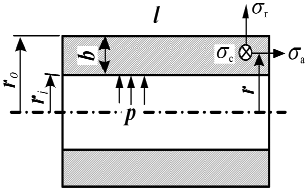
Dimensions and stress in a pressurized circular tube.
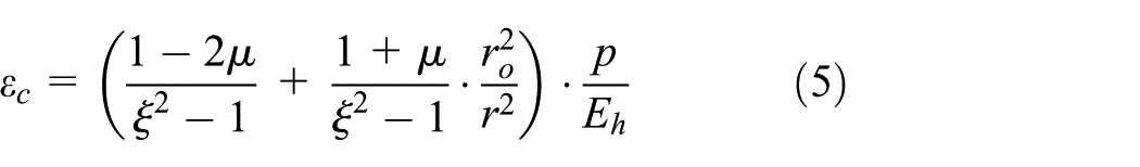
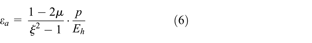
Considering that the shearing stress along three directions is equal to zero in such kind of circular tube, the strains in three directions at the point with radius r in the body of the circular tube can be expressed as

Suppose that the increment in pressure is
The increments of strains in tangential and axial directions are


The variables
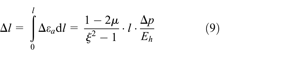

The increment in volume of the circular tube can thus be derived as

Considering that the nominal volume of the circular tube is


The relationship between
The value of
For a circular tube with thickness smaller than its inner radius, that is, radius ratio
It will be illustrated in the following section that the volume modulus of the circular tube has significant influence on the hydraulic stiffness.

The relationship between
Stiffness considering the flexibility of the circular tube
Figure 3 is the sketch map of a hydraulic cylinder. The meaning and value of all parameters are listed in Table 1. The effective sectional areas at two sides of the piston are

The sketch map of the hydraulic limb.
Considering the hydraulic system, as shown in Figure 3,

In fact, the volumes or, namely, the capacity of the circular tubes will also change due to the pressure fluctuation. Therefore, the deformation of the circular tube must be taken into account in calculating hydraulic stiffness.

According to the definition of bulk modulus of the fluid, one can obtain that

where

The stiffness coefficient of the hydraulic system can be written as

Substituting equation (17) into equation (18), the hydraulic stiffness with considering the structural flexibility can be solved as

The proposed formulation indicates that the stiffness of a hydraulic system is the result of comprehensive effect of fluid compressibility and structural flexibility. It is a nonlinear function with respect to the piston position. For a specific hydraulic system, when the fluid pressure is high, the variation of the pressure and the piston position are often considerable; therefore, nonlinearity of hydraulic stiffness is usually significant. In low-to-middle pressure range, the variation of the pressure and the piston position are usually very small; therefore, the nonlinearity of hydraulic stiffness is not too remarkable.
On the other hand, the flexibility of the circular tubes has significant influence on the hydraulic stiffness. Even though a hydraulic system works in low-to-middle pressure range, if the volume of the hydraulic cylinder is small and the volume of the fluid supply hose is relatively large, there could be big error between results calculated using traditional formulation and the experiments. Specifically, the hydraulic stiffness is affected by parameters of the circular tube such as the length, the inner and outer radius, and Young’s modulus.
Influences of parameters on the hydraulic stiffness
In this section, the influences of parameters of the circular tube on the hydraulic stiffness are investigated. The concerned parameters are Young’s modulus
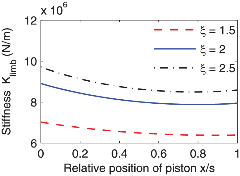
The relationship between the stiffness

Stiffness
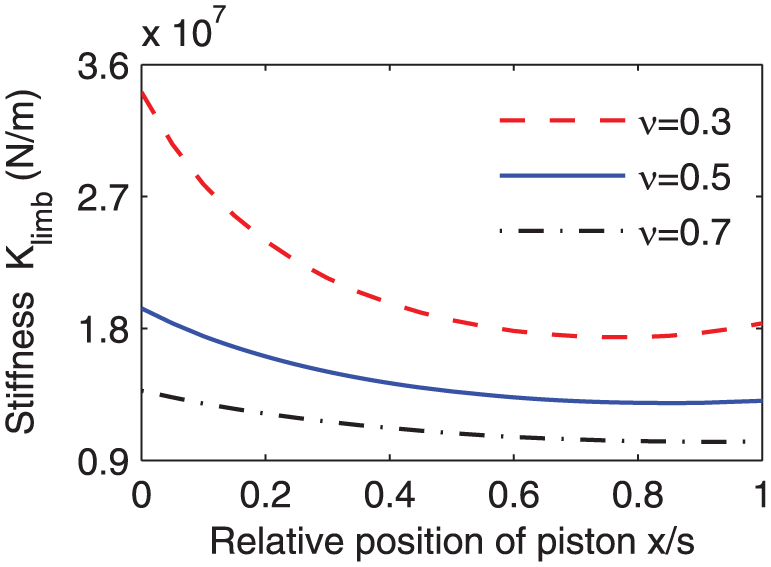
The relationship between the stiffness
Stiffness
The relationship between the stiffness
Stiffness
It can be seen that for most cases, the stiffness of hydraulic limb decreases as the position of piston x increases. This is probably due to the fact that the length of circular tube

Stiffness
According to analysis above, it can be concluded that
Higher hydraulic stiffness can be obtained by increasing Young’s modulus or the radius ratio or by decreasing the nominal volume ratio.
Modification of the length ratio of the circular tube can modulate the hydraulic stiffness at different positions of the piston.
Experiments and discussion
As shown in Figure 8, stiffness of the hydraulic limb as specified in Appendix 1 is measured on a WDW-100 Electronic Testing Machine. Compressive force is applied on two sides of the hydraulic limb, and both force and displacements are measured to calculate the stiffness. The measuring accuracy of the force is ±0.5%, and the measuring accuracy of the displacement is ±0.01 mm.

Experimental setup.
In order to avoid unnecessary disturbances and simplify the test, the chamber with rod is connected to a soft container and is full of non-pressurized hydraulic oil, which means the stiffness of this chamber is nearly zero. The chamber without rod is filled with pressurized hydraulic oil. This chamber is also connected with the circular tube by an on–off valve. If the valve is closed, the testing results stand for stiffness of the hydraulic limb without the circular tube. Or else, if the valve is open, the circular tube and the chamber without the rod serve as an entirety and the stiffness will decrease significantly. Besides, the stiffness is identified with fluid pressure near
Figure 9 shows comparison between simulation and experiment of stiffness for the hydraulic limb without the circular tube. In this circumstance, the proposed method is identical with the traditional one because there is no circular tube in the chamber without rod. It can be seen that the maximal relative error between the theoretical results and the experimental ones is 3.4%. Notice that the error depends mainly on the bulk modulus of the fluid, which is identified as

Stiffness of the hydraulic limb without the circular tube.
Figure 10 shows comparison between simulation and experiment of stiffness for the hydraulic limb with the circular tube. In this experimental setup, the circular tube is made of wire-braided hydraulic hose. The volume modulus of the circular tube is identified as

Stiffness of the hydraulic limb with the circular tube.
Conclusion
Structural flexibility is taken into account to formulate the nonlinear hydraulic stiffness of a hydraulic system. Theoretical analysis shows that larger Young’s modulus, larger radius ratio, and smaller volume ratio of the circular tube yield higher hydraulic stiffness. Besides, the nonlinear stiffness of a hydraulic limb varies with the changing of piston position and is significantly affected by the length ratios of the circular tubes at two sides of the cylinder. Experimental results have verified the presented method. The proposed method can be used to design hydraulic system for achieving desired static and dynamic performances.
Footnotes
Appendix 1
Parameters of a hydraulic system.

| Parameter | Value | Unit | Meaning |
|---|---|---|---|
| 0.060 | m | Outer diameter of the cylinder | |
| 0.040 | m | Inner diameter of the cylinder | |
| 0.020 | m | Diameter of the rod | |
| s | 0.188 | m | Effective moving range of the piston |
| 0.0095 | m | Outer radius of the circular tube | |
| 0.004 | m | Inner radius of the circular tube | |
| 2.000 | m | Length of the left circular tube | |
| 0 | m | Length of the right circular tube | |
| 2.16 × 10⁹ | Pa | Young’s modulus of the circular tube | |
| 0.36 | – | Poisson’s ratio of the circular tube | |
| 1.56 × 10⁹ | Pa | Bulk modulus of the fluid |
Academic Editor: Mark J Jackson
Declaration of conflicting interests
The author(s) declared no potential conflicts of interest with respect to the research, authorship, and/or publication of this article.
Funding
The author(s) disclosed receipt of the following financial support for the research, authorship, and/or publication of this article: This work was partially supported by the National Natural Science Foundation of China (nos 51435006, 51235005, 51405174, and 51421062).