
Abstract
The purpose of this work is to present a methodology for calculating the equivalent stiffness matrix of the wheel center of the vehicle suspension. For a suspension, the stiffness matrix of the wheel center, which is effected by the bushings and flexible linkages, control the suspension’s elasto-kinematic (e–k) specification. The equivalent stiffness matrix of the wheel center is formulated by using the stiffness of the bushings and linkages. And the models of series and parallel springs are used to calculate this equivalent stiffness matrix based on the number of the bushings and linkages. An example is presented to illustrate how to use the proposed methodology to derive the equivalent stiffness matrix of a suspension system with three bushings and flexible linkages. The results show that the equivalent stiffness of the wheel center will decrease if the linkage stiffness is considered. This methodology can be used in all kinds of suspension structure. It can also be used to optimize and design the suspension system.
Introduction
Suspension is the system of springs, shock absorbers, and linkages that links the wheels to the vehicle body and allows them to move relatively. 1 The role of the suspension is (a) to transmit the forces and torques between the wheel and the vehicle, such as support force, driving force, braking force, and cornering force; (b) to absorb the impact forces due to uneven road surfaces; (c) to attenuate the vibration caused by impacted forces; and (e) to keep vehicle occupants comfortable. A vehicle suspension is shown in Figure 1. Over the last few decades, many suspension designers have investigated the characteristics of the vehicle suspension and introduced the new suspension design technologies.
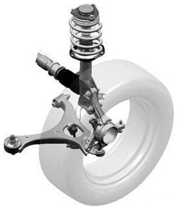
A vehicle suspension.
As an important parameter, suspension stiffness is used to establish a suspension model, optimize the vehicle suspension structure, and analyze vehicle vibration.2–5 Verros et al. 6 presented a methodology to optimize the suspension damping and stiffness parameters of nonlinear quarter-car models subjected to random road excitation. Georgiou et al. 7 developed a systematic methodology to select optimum values for the suspension damping and stiffness parameters of 2 degrees of freedom quarter-car models.
In order to use the design parameters targeted at the suspension level, Kang et al. 5 adopted a tabular elastic-kinematic suspension (TEKS) mode. In this model, the characteristic of suspension system can be taken as an elasticity system to the vehicle body, and the elasticity system can be modeled with a stiffness matrix. Gerrard 8 presented the Equivalent Elastic Mechanism (EEM) method to analyze and design the compliant suspension linkages. He considered the suspension system as a single elastic system connecting the wheel carrier to the ground and the compliant behavior of the elastic system can be represented in its entirety by a single stiffness matrix. Kazuhiro and Takashi 9 introduced a suspension design technology applying the principal elastic axes, which can optimize suspension geometry and bushing stiffness characteristics more quickly and effectively.
Some of the previous studies associated with the stiffness matrix include the following: Loncaric 10 found that there is a normal form for a generic compliance matrix when the stiffness assumes a normal form; Sanger et al. 11 developed a general method for the stiffness analysis of serial and parallel kinematic mechanism; Patterson and Lipkin 12 developed the compliant axes from the compliance matrix eigenvalue problem; and Saffari et al. 13 calculated the stiffness matrix of a curved beam element using the force–deformation relationship.
The equivalent stiffness matrix of the wheel center is very important for the suspension system. The stiffness of the wheel center is mostly provided by the bushings which connect the vehicle frame with the suspension and the stiffness of the bushing can be easily measured, and the linkages also provide the stiffness of the wheel center. To date, the relationship between the stiffness of the wheel center and the stiffness of the bushings has been well studied by Zhao et al.; 14 however, the flexible linkage was not considered.
The article describes a methodology which quickly calculates the equivalent stiffness matrix of the wheel center by using the stiffness of bushing and the linkages. This methodology can be applied in automotive design and the some machinery industry. First, the equivalent stiffness matrix of the wheel center of the system with one bushing and one linkage is calculated. For the structure with Multi-bushings and multi-linkages, it is modeled as a suspended ridge body with several springs in parallel. Based on this model, the equivalent stiffness of this structure is calculated. Finally, numerical example for a simple mechanism with three bushings and flexible linkages is presented and discussed.
Calculating the equivalent stiffness matrix of a suspension
The following assumptions are made for calculating the stiffness matrix of the wheel center of the wheel carrier:
The linkages of the suspension are flexible.
The stiffness of the suspension system is provided by the bushings and the linkages.
The position of the linkages, the material, and the geometric parameters of the linkages are known.
All the unknown force direction are set to coordinate with the positive direction of the Global Co-ordinate System (GCS).
We only consider the case of small rotations displacement and assume that all the stiffness is linear.
The linkages directly connect the wheel center to the bushings.
These assumptions do not introduce significant error when we consider typical loads applied in the wheel center.
Suspensions typically have numerous bushings and linkages that connect the wheel carrier with the vehicle body. In other words, we are able to consider the suspension to be a simple system connecting the wheel carrier to vehicle body with the stiffness. So we can express a suspension system by its stiffness

There is a kinematic assumption that the real motion of the bodies (i.e. absolute motion) can be approximated to be regarded as the superposition of rigid body motion and elastic motion. We start from the simplest case.
One bushing and one flexible linkage
There is only a bushing and a flexible linkage, as illustrated in Figure 2. Point 0 represents the location of the wheel center, whereas a single bushing is situated at Point 1 and is connected to the wheel center with a flexible linkage.

One bushing and one flexible linkage structure.
In general, the bushing and flexible linkage between the wheel and vehicle can be modeled as two springs in series, as shown in Figure 3. Their equivalent stiffness matrix,

where

Springs in series.
The stiffness matrix of bushing 1
Using the theoretical mechanics knowledge, the force of the bushing can be written as

The displacement of the bushing can be obtained using equation (1), namely, the displacement of Point 1

The displacement of the Point 0 caused by bushing, namely, the displacement of the wheel center, can be calculated using the rigid body kinematics knowledge. And, this displacement is expressed as follows
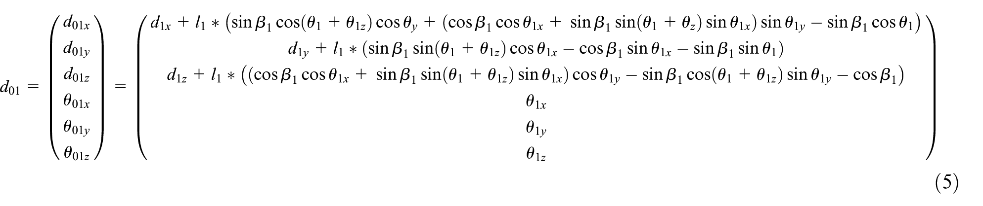
Based on assumption (5), the following equations can be obtained
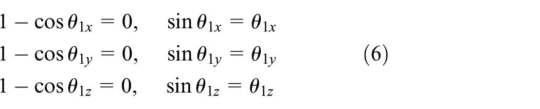
Therefore, equation (5) can be written as the following simplified equation

Comparing equations (3) and (7), the following equation can be obtained:
Equation (5) also can be written as follows:
So, the stiffness matrix of bushing 1 at the wheel center is expressed as follows

The stiffness matrix of linkage 0–1
First, a new coordinate system is established; the x-axis of this new reference along the linkage direction is 0–1.

where

Figure 4 shows the force diagram in xy plane of the new coordinate:
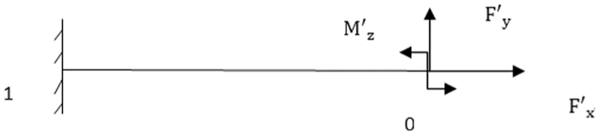
The force diagram in 0–xy plane.
Then the displacement of the wheel center can be calculated according to the knowledge of the mechanics of materials:
The displacement in the x-direction
The displacement in the y-direction
The rotation in the z-direction
Similarly, the other displacement of the wheel center can be obtained as follows:
The displacement in the z-direction
The rotation in the x-direction
The rotation in the y-direction
Writing the above six equations into the matrix form

So, the displacement in the global coordinate system can be expressed as

The stiffness matrix of linkage 0–1 at the wheel center is

According to equation (3), the equivalent stiffness matrix

Multi-bushings and multi-linkages
In this section, a vehicle wheel with n (n°>°2) bushings and n (n°>°2) linkages is shown in Figure 5.

n bushings and n flexible linkages structure.
Here, this mechanism with multiple bushings and linkages can be modeled as an elastically suspended ridge body with several spring supports in parallel, as shown in Figure 6. Their equivalent stiffness matrix at the wheel center,

where
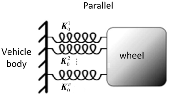
Springs in parallel.
For the part 0–i, assume that the displacement caused by the bushing i and flexible linkage 0–i are
According to equation (7),

where

Based on equation (3), the equivalent force at the wheel center is expressed as

where

Comparing

The
So, the stiffness matrix of bushing i at the wheel center is expressed as
Then, the displacement caused by the flexible linkage 0–i can be calculated using equation (9)

where

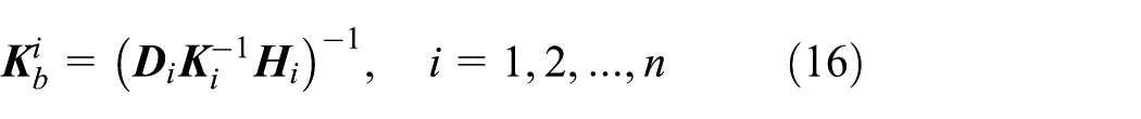
The stiffness matrix of linkage 0–i at the wheel center is

According to equation (3), the equivalent stiffness matrix

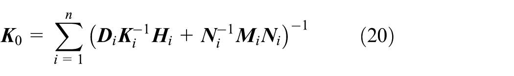
Based on equation (12), the equivalent stiffness matrix of suspension structure with multiple bushings and linkages is expressed as
Numerical examples
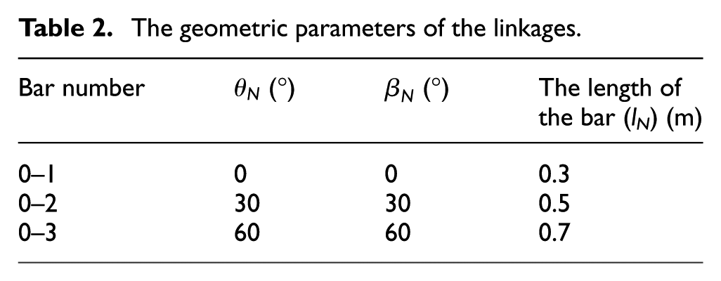
In this section, the above method is applied to calculate the equivalent stiffness matrix of the wheel center. The mechanism has three bushings and three linkages. The stiffness of the bushings is elaborated in Table 1. The geometric parameters of the linkages are elaborated in Table 2.
The stiffness of the bushings.

The geometric parameters of the linkages.
According to equation (20), the equivalent stiffness matrix of the wheel center

While the stiffness of the linkage does not considered, the equivalent stiffness matrix of the wheel center

These results show that the value of the equivalent stiffness matrix of the wheel center will decrease if the stiffness of the linkages is considered.
Conclusion
This study presents a methodology for calculating the equivalent stiffness matrix of a wheel suspension system with a specific number of bushings and linkages. In this methodology, the equivalent stiffness matrix of a suspension system is obtained based on the models of series and parallel springs. Besides, the relationship between the stiffness matrix of the wheel center and the stiffness of the bushings and linkages is established, which provides insight into the function of the bushings and linkages of the suspension. An example is presented to illustrate how to use the proposed methodology to derive the equivalent stiffness matrix of a suspension system with three bushings and flexible linkages. The results show that the value of the equivalent stiffness matrix of the wheel center will be reduced if the stiffness of linkages is considered. The presented methodology can be used to optimize the suspension system.
Footnotes
Academic Editor: Jianqiao Ye
Declaration of conflicting interests
The author(s) declared no potential conflicts of interest with respect to the research, authorship, and/or publication of this article.
Funding
The author(s) disclosed receipt of the following financial support for the research, authorship, and/or publication of this article: This work was supported by the China FAW Group Corporation R&D Center, Project 985-Automotive Engineering of Jilin University, and Natural Science Foundation of Jilin Province (20160101280JC).