
Abstract
This article numerically investigates the effects of revolute joint clearance and structural flexibility on the overall dynamic characteristics of a deployable solar array system. Considering torque spring, close cable loop configuration, and lock mechanism, a typical mechanism composed of a main body with a yoke and two panels is used as a demonstration case to study the effects of clearance and flexibility on the dynamic response of the deployable solar array system in the deployment and lock process. The normal contact force model and tangential friction model in clearance joint are established using Lankarani Nikravesh model and modified Coulomb friction model, respectively. The numerical simulation results reveal that the coupling of clearance and flexibility makes different effects on the dynamic characteristics of the deployable space solar arrays for different operation stages. Besides, the clearance and flexibility of a mechanical system play crucial roles in predicting accurately the dynamic response of the system, which is the foundation of mechanism design, precision analysis, and control system design.
Introduction
Solar array, which provides necessary power for the whole system, is a vital component of the spacecraft widely used in space applications. 1 Deployable multiple-panel solar array system can be transformed from folded configuration during spacecraft launch and ascent to an expanded form with a larger volume when the spacecraft is turned into free flying orbit. The failure of the solar array deployment would be a disaster for a space mission. Therefore, it is very important to study the dynamic characteristics of the deployable space solar array system.
Dynamics of the deployable space structure with pinned joints can be divided into two parts: one is the flexible multibody dynamics, and the other is the clearance problem in joints. 2
Up to now, the deployment of flexible solar array has been studied by many researchers. Wallrapp and Wiedemann 3 used the multibody program SIMPACK to simulate the deployment of a solar array three-dimensionally and to check the influence of the flexibility of the solar array on the solar generator motions. The comparison of the results shows that flexible bodies cause a slightly changed torque in the closed cable loops. Y Kojima et al. 4 simulated the ADEOS spacecraft attitude response due to the stick-slip effect and evaluated their mathematical model of spacecraft, which composed of a main rigid body and flexible appendages. The attitude stability of flexible spacecraft is discussed in this article. XS Ge and YZ Liu 5 derived the Euler’s equations of forced vibration of two flexible solar arrays and discussed attitude stability of flexible spacecraft. E Gao et al. 6 presented the methodology on modeling and simulating the deployment and locking processes of flexible solar panels for a satellite and revealed that the deployment process of flexible solar panels impacted the attitude of satellite. These researches provide a significant foundation for studying the dynamic characteristics of deployable flexible solar array system during deployment.
On the other hand, many scholars have done a lot of researches on the deployable mechanisms with clearance joints. Clearance in joints is the necessary condition to ensure the deployable structure deploy smoothly and reliably. The emergence of the contact, collision, friction, and impact in clearance joints will cause severe vibration and nonlinear dynamic responses of the deployable space structures.7,8 The clearance joints in multibody system cause significant effects on the deployment kinematics performance and dynamic performance. Flores 9 proposed a computational methodology to quantify the influence of the clearance size, friction coefficient, and number of clearance joints on the dynamic response of planar rigid multibody systems, which provided references for the dynamic analysis of multibody mechanical systems with multiple clearance joints. Besides, Flores et al.10,11 showed that the existence of dry friction at joint clearances caused high peaks on the kinematic and dynamic responses when compared to those obtained with lubricated model. The performance of the lubricated joint is closer to that of an ideal joint. Muvengei et al. 12 numerically investigated the parametric effects of differently located frictionless revolute clearance joints on the overall dynamic characteristics of a multibody system, and the results showed that location of the clearance revolute joint, the clearance size, and the operating speed of a mechanical system play crucial roles in predicting accurately the dynamic responses of the system. Bai and colleagues13,14 quantitatively investigated the dynamic responses of a typical multibody system with revolute clearance joints and investigated effects of clearance on dynamic responses of rigid dual-axis positioning mechanism of a satellite antenna. These studies and investigations revealed dynamic characteristics of mechanisms with clearance joints and provided basic modeling and analysis methods for some typical multibody systems.
However, researches on the effects of coupling of clearance and flexibility on the dynamics of a deployable mechanism, such as space solar arrays system, are insufficient for predicting the in-orbit performance of developable space mechanisms with clearance joints. J Li et al. 15 revealed that evidently nonlinear dynamic characteristics existed in the multibody deployable mechanism and investigated the effects of clearance, damping, friction, gravity, and flexibility on dynamic performance of multibody system. In addition, computational methodologies are presented for modeling and analysis of flexible planar multibody systems with clearance and lubricated revolute joints.16,17 Zheng and Zhou 18 and Khemili and Romdhane 19 conducted the dynamic modeling of rigid-flexible coupling slider-crank mechanism with clearance based on the analysis/design software ADAMS. However, the coupling effects of joint clearance and structural flexibility on the dynamics of deployable space solar arrays is a complex nonlinear issue. Different from general closed multibody system, the deployable space solar arrays, as open multibody system, have their own dynamic phenomena, which is influenced by the particular close cable loop (CCL) configurations and lock mechanisms. The dynamic modeling of multibody solar array system with a full understanding of coupling between clearance and flexibility is an important foundation for simulation, design, analysis, optimization, and control of the mechanisms and manipulators.
Thus, this article establishes the dynamics model of solar array system with clearances, which consists of a main body, a flexible yoke and two flexible panels connected with clearance joints, torque springs, CCLs, and lock mechanisms. Then, the contact force model and friction effect model in the clearance are established. Finally, the effects of coupling of clearance and flexibility on the dynamic characteristics of the deployable space solar arrays are investigated.
Dynamic representation of solar array system with clearance joints
Structure of spacecraft system
Solar array system is the critical appendages of spacecraft. The spacecraft system adopted in this article is shown in Figure 1, which consists of a main body, a yoke, and two solar panels connected by revolute joints. The preloaded torsion springs located at each revolute joint provide the energy to deploy the arrays. The CCL configurations are applied as synchronous deployment control mechanism of appendages composed by a yoke and two solar panels. Besides, lock mechanisms located at revolute joints play a role in locking the arrays in the proper position.

The structure of solar array system: (a) in folded condition, (b) the CCL connection diagram, and (c) the cable torque analysis model.
Torque spring mechanism
The preloaded torque spring drives the array deployment in a preset speed. The dive torque

where K is the torsional stiffness of torsion spring;
CCL configurations
CCL configurations as shown in Figure 1(b) are applied to achieve synchronous deployment of solar arrays. Folded arrays are released in orbit under the control of the flexible CCL configuration by synchronizing the deployment angles during the deployment. The CCL mechanism comprises synchronous wheels and pre-tensioned close-loop cables. Figure 1 illustrates the forces and torques of a typical CCL. The tight-side tension

where
When the two arrays are not synchronous, the tight-side tension
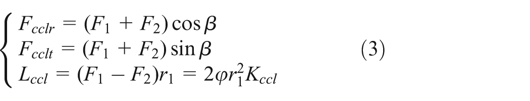
where
CCL configurations synchronize the deployment angles of each panel by applying a passive control torque proportional to the angle difference. Therefore, the torques of passive control (Figure 1(c)) can be regarded as
where
Lock mechanism
A schematic diagram of lock mechanism is shown in Figure 1. The joint connects two bodies A and B separately; the two bodies rotate relatively round the joint D. The pin E can move on the surface of C in the deployment process. The pine slide into the groove until the deployment angle
A STEP function and a BISTOP function are introduced to present the equivalent moment


where
Clearance revolute joint model
Multibody system with joint clearance dynamics model
The intermittent collision and friction exit inside the clearance joints of multibody system. The relative motion states of pin and sleeve are divided into the free movement and contact deformation phases. The dynamics equation of multibody system is calculated using the Lagrange multiplier method. In the free movement phase, the system dynamic equation can be described by

where
In the contact deformation phase, the contact forces occur in the clearance joints between two colliding bodies. Thus, the system dynamic equation can be obtained by

where
As shown in Figure 2, the types of contact force in clearance joints contain normal contact force

Clearance joint model: (a) free movement and (b) contact deformation.
Normal contact force model
Force normal to the direction of contact appears when the pin makes contact with the sleeve. Hertz contact law reveals the contact force as a nonlinear function related to penetration depth. Unfortunately, Hertz contact law cannot be used in compression and restitution phase of contact as the law ignores the energy dissipation during the impact process. Lankarani and Nikravesh 20 modified the Hertz contact force model considering energy dissipation during the impact process by introducing a hysteresis damping function. The Lankarani Nikravesh model including the energy dissipation in the form of internal damping has been adopted by a lot of researchers and has been proved effective by comparing the theoretical results and the related experimental ones. Thus to accurately investigate the dynamic performance of multibody system with revolute clearance joint and calculate the contact force in clearance joint, in this article, the nonlinear contact force model proposed by Lankarani and Nikravesh is applied for the contact force model between the pin and sleeve. It can be expressed as

where

where

where

Tangential friction force model
In addition to the normal contact force, the clearance joint forces may be enhanced by considering the effect of friction. Tangential motion between two contact bodies contains relative slip status and viscous status. In this article, a modified Coulomb friction model with better numerical features is applied to describe the dry friction response between the pin and sleeve. The direction is tangent to the contact surface. It can be evaluated as

where friction coefficient

where
Numerical simulation model of deployable solar array system
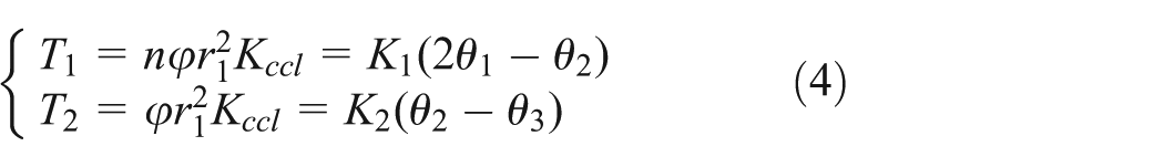
A deployable solar array system with clearance is modeled to analyze the dynamic responses of the solar array system during initial operation stage, deployment stage, and pre- and post-system lock stage, which is shown in Figure 3. The physical parameters of main body, yoke, and panels are shown in Table 1. In this article, the material of yoke and panels is aluminum, its density is

Simulation model of solar array system.
Geometrical and physical parameters of the solar deployment system.

Flexible yoke: three typical eigenfrequencies and eigenmodes: (a) first mode and natural frequency: 2.72 Hz, (b) second mode and natural frequency: 3.26 Hz, (c) second mode and natural frequency: 5.07 Hz, and (d) meshing elements of yoke.

Flexible panel: three typical eigenfrequencies and eigenmodes: (a) first mode and natural frequency: 0.45 Hz, (b) second mode and natural frequency: 1.79 Hz, (c) second mode and natural frequency: 3.09 Hz, and (d) meshing elements of panel.
Geometrical and physical parameters of revolute joints.

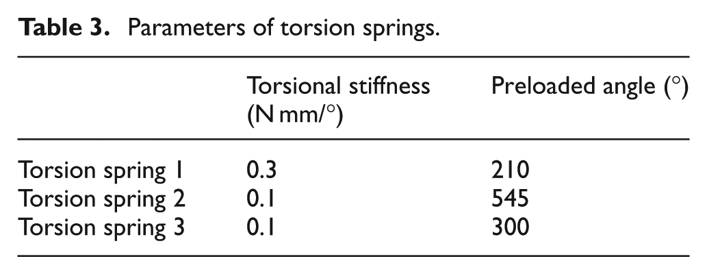
Parameters of torsion springs.
Contact parameters.
Results and discussion
Dynamic responses of deployable rigid solar array system with ideal joints
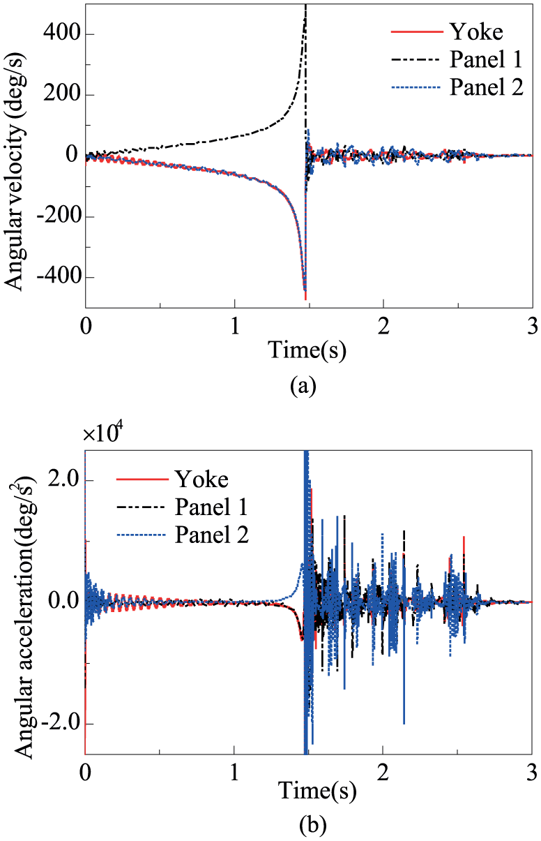
The folded solar array system is released driven by torsion springs and deployed under the control of CCL mechanism. Finally, the whole system is locked at the expected deployment position by the lock mechanism. The dynamic response of deployment of rigid solar array system with ideal joints is calculated, as shown in Figure 6. The measurement objects (yoke, panel 1, and panel 2) are shown in Figure 3. Figure 6 illustrates that speed fluctuation happens in the deployment process due to the synchronous adjustment torques provided by CCL mechanism. Furthermore, a sudden change in the angular accelerations occurs at the end of deployment due to the lock torques provided by lock mechanism. After locked, the system can quickly achieve stability through a short time little jitter.

Dynamic responses of rigid solar array system with ideal joints: (a) angular velocity and (b) angular acceleration.
Effects of clearance
The deployment of the rigid solar array system with three 0.1-mm clearance joints is simulated to study the effect of clearance joints on dynamic performance of the structure. Taking results of yoke as an example, Figure 7 shows the angular velocity responses of rigid solar array system considering joint clearance. Figure 7(a) shows that the solar array system with clearance joints needs more time to achieve the deployment to the expect lock position influenced by the tangential friction force. Moreover, the speed fluctuation amplitude of the system with clearance reduces in the deployment process. Because the clearances can change the relative position between the pin and the sleeve, that decrease the deployment asynchrony angle in proportion to the synchronous adjustment torques provided by CCL mechanism according to equation (4), as shown in Figure 8.

Angular velocity responses of rigid solar array system with 0.1-mm joint clearance: (a) the whole stages, (b) initial stage and (c) post-lock stage.

Synchronous adjustment torques provided by CCL1 mechanism. IJ-T: the torque close to the main body for system with ideal joint; IJ-T′: the torque far from the main body for system with ideal joint; C-T: the torque close to the main body for system with clearance; C-T′: the torque far from the main body for system with clearance.
Furthermore, Figure 7(b) shows that clearances lead to severe impacts between pins and sleeves at the beginning of system operation. Besides, Figure 7(c) shows that the system with clearance needs more time to achieve stability and shake violently after locked because the contact force and lock force coupling provides a serious of discrete instantaneous impact force on the joint with clearance. Figure 9 shows the effect of clearance on solar array system lock torque at joint 1. Due to the joint clearance, pins and sleeves impact at the beginning of the system motion and keep on contact and impact in the later period after locked. The clearance in the joints influences the positioning accuracy, movement stability, and reliability of the mechanism system.

The lock torque of rigid solar array system with 0.1-mm joint clearance.
Effects of flexibility
Deployment of the flexible solar array system with ideal joints is simulated to study the effect of flexibility on the dynamic performance of solar array system. Compared with rigid bodies, elasticity deformations of flexible yoke and panels coupled to the rigid motion have a significant effect on the dynamic response of deployable solar arrays. The angular velocities and angular accelerations of flexible bodies shown in Figure 10 are markedly different with the results of rigid bodies shown in Figure 6. The vibrations of flexible bodies are more evident at two phases: the beginning of operation and after locked. At the moment of deployment startup, the sudden driving force causes the vibration of the flexible bodies; flexible bodies keep vibration for a period after locked.
Dynamic responses of flexible solar array system with ideal joints: (a) angular velocity and (b) angular acceleration.
Effects of clearance and flexibility
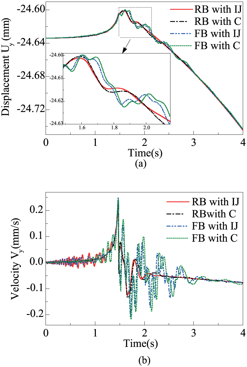
Taking results of panel 2 as an example, Figure 11 shows the effect of clearance and flexibility on the angular velocity responses flexible solar array system. Compared with the rigid body, the flexible body has speed fluctuation caused by the synchronous adjustment torques and vibration caused by its own elastic deformation in deployment, as shown in Figure 11(b). Moreover, the clearances decrease vibration of the flexible body in most of deployment stage because the clearance can be seen as the equivalent spring-damping model calculated using equations (10)–(12). It means that flexible bodies with clearances can be seen as they with spring-dampers, which can control the system vibration compared to the ideal joints. Furthermore, solar array system has the larger vibration amplitude and the longer vibration time under the coupling effect between elastic vibration and impact in clearance joint before and after the lock time, as shown in Figure 11(b) and (c). Figure 12 shows the contact force at joint 3 in four cases: rigid bodies with ideal joints, flexible bodies with ideal joints, rigid bodies with clearances, and flexible bodies with clearances. For the cases of flexible yoke and panels, the maximum values of impact are highly reduced; the elastic yoke and panels act as a suspension system for the mechanism. However, obviously, flexible bodies with clearances have a serious of discrete instantaneous contact force at the post-lock stage because solar arrays as large flexible structures will remain excited for a long time after deployment. The structural vibration causes oscillation of the whole system and intensifies collisions at clearances between pins and sleeves. Compared with the contact force of rigid body with clearance, the clearance contact force of flexible body is denser and influenced by the coupling of elastic vibration and impact, especially pre- and post-lock time.

Angular velocity responses of flexible solar array system with 0.1-mm joint clearance. RB with IJ: rigid bodies with ideal joints; FB with IJ: flexible bodies with ideal joints; FB with C: flexible bodies with clearances: (a) the whole stages, (b) initial stage, (c) pre-lock stage and (d) post-lock stage.

Contact force at joint 3.
The relative position track between the center of pin and sleeve at the clearance joint 1 is shown in Figure 13, and the impact frequency becomes obviously higher and impact trace is more disordered. Figure 14(a) and (b) shows time histories of the displacement and velocity in y direction of the mass center of spacecraft main body in four cases, respectively. The unbalanced driving moment, lock torque, contact, impact, friction force, and so on generated by deployment of solar arrays may disturb spacecraft attitude. The results indicate that the clearance and flexibility of the solar arrays system have obvious effects on the dynamic characters of space main body. Clearance and flexibility change the lock position accuracy and deployment time. Rigid body with ideal joints has more obvious velocity perturbation in the deployment process, while the clearance and flexibility led to system vibration seriously at the initial operation stage and pre- and post-system lock stage.

Impact track of the clearance joint: (a) impact track of rigid bodies and (b) impact track of flexible bodies.
Displacement and velocity of main body of spacecraft: (a) displacement and (b) velocity.
Conclusion
Numerical simulations are conducted to reveal the effects of joint clearance and structural flexibility on the dynamic response of deployment of solar arrays system, which consists of main body, yoke, panels, torque spring mechanism, CCL mechanism, and lock mechanism. A contact model in joint clearance is established using the nonlinear Lankarani and Nikravesh model and the friction effect is considered using the amendatory Coulomb friction model.
The simulation results show that considering joint clearance and structure flexibility, the coupling between the structural elastic vibration and impact contact in clearance joint has significant effects on the dynamic characteristic of the deployable mechanism. Joint clearance generates impact force to disturb the deployment of solar arrays system, especially at initial operation stage and post-lock stage. Moreover, joint clearance generates friction force to delay the time for arrival of the expected lock position, while clearance can increase stability in deployment stage by adjusting the relative angle between pin and sleeve to reduce synchronous adjustment torques provided by CCL mechanism. Furthermore, the coupling of flexibility and clearance can be seen as a suspension system that may reduce the speed fluctuation in deployment stage, while the coupling of elastic vibration and impact in clearance joint further intensifies the jitter and instability of solar arrays system pre- and post-lock stage, which significantly affects the dynamic characteristic of the deployable system.
Besides, joint clearance and structure flexibility have significant effects on the satellite attitude with deployable mechanism. Therefore, in order to design effective controllers for eliminating the chaotic behaviors brought about by the non-linearity of joint with clearance and the complex couplings of vibration and shock of flexible body, the difference effects of clearance and flexibility on the dynamic characteristic of the deployable mechanism in different operation stage should be understood.
The investigation supports the idea that the modeling of clearance and flexibility must be considered in analysis, design, and control of the deployable solar array system. Numerical simulations of deployment of solar arrays system under the gravity may be focused on in the future. Then, experimental research is necessary to verify the simulation analysis.
Footnotes
Academic Editor: Mario L Ferrari
Declaration of conflicting interests
The author(s) declared no potential conflicts of interest with respect to the research, authorship, and/or publication of this article.
Funding
The author(s) received no financial support for the research, authorship, and/or publication of this article.