
Abstract
Joint clearance is unavoidable in the revolute joint of multi-link mechanism. Excessive value of joint clearance generally leads to the noise, vibration, and fatigue failure. In this paper, a multi-link articulated mechanism system with three revolute clearance joints is selected as the study object. At first, its ideal motion equations and dynamic responses without joint clearance are outlined. Then an experimental rig is set up, and the acceleration responses of the mechanism in different scenarios are investigated. Comparative analysis indicates that in the presence of joints clearance, clear periodic transient impacts appear in the acceleration outputs while this mechanism moves to specific positions, and the impacts amplitude increases along with the clearance size and driving speed. Also, certain sequence among three motion states of clearance joint, named free flight, penetration and continuous-contact is observed twice in one circle movement of the mechanism. Besides, the clearance joint at the end of the transmission chain has greater effects on the mechanism system than the other joints. Finally, flexible rubber sleeves are set into the clearance joints, and the obtained experimental results indicate that the undesired transient impact by clearance joints on the mechanical system can be suppressed by flexible sleeves.
Introduction
For more complex motion and load transfer, multi-link articulated mechanism is widely utilized nowadays. In general, for the assembly and mobility, joint clearance is unavoidable between the adjacent components in this type of mechanism.1,2 In the joint clearance space, repeated free flight, continuous-contact and penetration between journal and bushing are introduced. Joint clearance is considered as the main source of impact forces and vibrations for mechanism system. Meanwhile, the joint clearance size also increases along with the wear between the journal and bushing in the clearance joint, which further degrades the performance of the mechanism, that is, decreased accuracy and service life.3–5
As the expectation for improved performance of modern mechanical systems increases, joint clearance has attracted attention. In the past decades, three types of theoretical models were proposed to describe the relative motion between the journal and the bushing in a clearance joint, including the three-motion model, 6 two-motion model, 7 the continuous-contact model, 8 as well as non-circular shapes contact model. 9 Valuable mathematical models were established for the normal contact force calculation, including the Hertz model, Kelvin-Voigt model, 10 Hunt-Crossley model, 11 Lankarani-Nikravesh model. 12 Additionally, Flores et al. 13 made comparatively analysis among different contact force model, which indicated that the Lankarani-Nikravesh model is more effective to depict the dynamic behavior of complicated mechanical systems with multiple revolute clearance joints. More well established and recently introduced contact-force models as well as their applicability for different multi-body systems were described by Luka et al. 14 As for the tangential force calculation in clearance joints, linear and nonlinear staged friction models were presented.15,16
For a more comprehensive investigation into the dynamic responses of articulated mechanism with clearance joint, amounts of valuable experimental and theoretical works have been completed. Flores et al. 17 and Tian et al. 18 made contributions to massless-link, spring-damper and momentum exchange mathematical models for the calculation of impact forces in clearance joint. Bai and Zhao 19 proposed a hybrid contact model with improved stiffness and damping coefficient algorithms for the impact forces calculation between the journal and the bushing in clearance joint. Chen et al. 20 and Hou et al. 21 numerically analyzed the chaos phenomena in the dynamic responses of a multi-link articulated mechanical system with clearance joint. In high-speed condition, the movement could transition from periodic state to quasi-periodic state, and eventually to chaotic state, which lead to reduced motion accuracy and shortened service life for these mechanism systems. What’s more, kinematic accuracy loss quantification, wear prediction due to clearance joints and the optimization design of articulated multi-link mechanism were also further analyzed widely.2,3,22 These experimental and numerical investigations indicated that, the clearance joints are the main source of severe nonlinear vibration output. Huge impact forces can be introduced, which leads to strong vibration, and eventually deteriorates the performance of the mechanical system. 23
Besides, with the consideration of component flexibility, the performances of the mechanism with one clearance joint were also widely explored.24,25 Erkaya 26 made valuable works about the coupling effects of component flexibility and joints clearance experimentally, it was revealed that the damping effects of a flexural pivot make the dynamic outputs of the slider-crank mechanism more stable. Besides, the damping effects of a flexible part would change with driving speed and clearance size. On the other hand, along with the development of Computer-aided engineering (CAE) technology, some numerical simulation software are gradually introduced to the dynamic analysis of flexibility effect of multi-link articulated mechanism. 27 more result comparison of rigid mechanical structure by reduced order method and its flexible counterparts by finite element analysis can be found.28–29 However, while considering flexibility effect and contact in clearance joints simultaneously, the simulation solving process generally non-convergence, and it can also be painstaking and prohibitive in terms of computation time.
Complicated coupling effect exist between clearance joint and parts’ flexibility on the multi-link articulated mechanism.30,31 Some scholars focused on the reliability improvement and decrease of undesired effects of clearance joint by applying that coupling effect. For instance, Erkaya et al. 32 replaced the rigid parts in the mechanical system with more flexible counterparts, by that method, the vibration energy introduced by clearance joint was dissipated by the damping effect of flexible components. Therefore, better kinematic stability was obtained as compared with the high-rigidity mechanism. On the other hand, it also greatly increased system flexibility which decreases the moving accuracy of the mechanism. Apart from this that, additional springs were set to the adjacent mechanical linkages to prevent the separation between the journal and bushing in clearance joints. 33 However, extra resistance torque would also be introduced by the extra spring, which might aggravate the wear effects of the clearance joint. Meanwhile, by experimental studies, Wang et al. 34 revealed that the shaft in clearance joint with lower stiffness can lead delay effects to the mechanical system, yet have no effect on the maximum vibration frequency of the studied mechanical system. More complicated coupling effects of panel flexibility and joint clearance on the mechanical system were analyzed numerically by Li et al. 35 It was observed that as the number of clearance joints increased, the damping effects of flexible links would decrease.
At present, most of the researches focus on simple crank-slider or four-bar mechanisms, with one clearance revolute joint, while the research on dynamic responses of planar multi-link mechanisms with multiple clearances is less. It is noteworthy that the overall analysis becomes much more complicated once more clearance joints are taken into account. 36 However, multi-link articulated mechanisms are increasingly common nowadays which generally contains an extended transmission chain. As a result, more clearance joints exist in this type of mechanism system, which makes the dynamic responses more sensitive and unstable. Unreasonable joint clearance size would also cause severe wear effects and eventually further harm the stability of the mechanism. Therefore, a multi-link articulated mechanism system with three clearance joints is considered in this paper. An experimental rig is constructed for the case studies on the effects of joint clearance under varying joint clearance size and driving speed. Further, flexible rubber sleeves were set between the adjacent journal and bushing to reduce the negative effects of joint clearance. The organization of the paper is given as follows: Section 2 outlines the structure and ideal motion equations of the multi-link articulated mechanism. Section 3 describes the constructed experimental system. The obtained results and comparative analysis are given in Section 4. Section 5 concludes for the whole paper.
Description of the multi-link articulated mechanism
Figure 1 shows the schematic of the studied articulated mechanism, consisting of a crank-rocker and a rocker-slider mechanism in series. Responsible for its extended transmission chain with multiple clearance joints, its dynamic responses are more unstable and more sensitive to clearance joint. In general, acceleration response contains important dynamic information for the mechanism system. 37 Meanwhile, as the final component, the acceleration response of the slider reflects the performance of the whole mechanism. Thus, the acceleration output of the slider is considered in this study for the analysis of the effects of joint clearance on the multi-link articulated mechanism.

Schematic of the multi-link articulated mechanism.
In ideal motion equations building process, the ideal planar revolute joint is generally treated as kinematic joints with only one rotational degree of freedom between the adjacent components. In that case, the dynamic output of the slider can be obtained through the solution of self-closing vector equation of the multi-link articulated mechanism
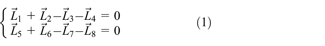
where L1−L4 represent the distance between neighboring joints in the crank-rocker mechanism in Figure 1. θ1−θ4 are the attitude angle of each link, and θ1 is employed as initial input boundary angle of the crank for the analytical solution. The value of L1−L4 and θ4 are constant. L5 and L6 represent the distance between adjacent joints in the rocker-slider mechanism and L8 is the distance between the slider and coordinate system in the x direction. Further, decomposing the vector equation into x and y direction, and substitute θ5=θ3+π, the vertical displacement of the slider can be obtained as

In this work, the analytical acceleration output of the slider is obtained by calculating the second derivative of equation (2), and then compared with that from experimental results. It worth to be mentioned that ideal acceleration response without joint clearance is impossible for multi-link articulated mechanism under the cumulative effects of multiple clearance joints since the joint clearance is inevitable in a real environment. The two translational degrees of freedom in the horizontal and vertical directions between the journal and bushing are introduced by joints clearance. Consequently, the journal and bushing can move relatively to each other. Frequent penetrations and rebounds appear in the clearance joint after the journal contacts the bushing surface. Essentially, the dynamic behaviors of the journal and bushing are determined by contact and impact forces between them.
Description of the experimental system
As shown in Figure 2, more clearance joints are considered, and the structural parameters and relative motion states of the journal and bushing are variable. For instance the coefficient of contact stiffness varies with the depth of contact and length of bearing. Thus, the dynamic equations of the study multi-link mechanism system with revolute clearance joints would feature strongly nonlinear characteristics, which make the numerical solution quite complicated. 38 In this work, for the investigations of effects of joint clearance on the mechanism, the experimental method is adopted.

3D model of the mechanism.
Joints A, B, and C in Figure 2 are selected for the experimental investigations of clearance joint effects on the dynamic responses of the mechanical system. For the other three joints, they are manufactured under the strict control of sixth level assembly tolerance, whose clearance size is within 11 µm, far less than the studied range. Therefore, their effects on the mechanism system are ignored. An experimental test rig, as described in Figure 3, is set up for different case studies.

Experimental rig for the multi-link articulated mechanism.
In the experimental rig, the input link is driven by a servo motor, which has a high precision control unit to ensure accurate driving speed. An accelerometer is screwed into a magnet and then attached to the slider of the rocker-slider mechanism. To reduce the frame vibration caused by the mechanism and the environment, the whole mechanism system is fixed to a cast iron platform by clamps. The structure parameters of the studied multi-link articulated mechanism are given in Table 1.
Structural parameters of the mechanical system.

For the measuring system, sensor and data recording systems are important since the analysis is based on obtained experimental data. The measuring system of Brüel and Kjær that features high precision and strong anti-disturbance abilities is utilized. For accurate vibration measurements, accelerometer performance should be selected based on the maximum vibration burst that can be expected for the breaker drive mechanism. The CCLD/IEPE accelerometer type 4534-B-001 is selected to record the acceleration. Its performance parameters include sensitivity of 10.54 mv/(m/s2), measuring range of ±700 (m/s2), and upper-frequency limit of 12.8 kHz, with a nonlinearity of 0.3%. The vibration recorder type 3053 capable of a 25.6 kHz sampling frequency is used.
Results analysis
Effect of driving speeds
In the first experimental case, 0.1 mm of artificial clearance is arranged in the three revolute joints (journal diameter of 11.8 mm and bushing diameter of 12 mm). Then, the input crank is driven by six driving speeds: 60, 120, 180, 240, 300 and 360 rpm. We collect the acceleration responses of the multi-link articulated mechanism system for two full crank rotations after steady-state has been reached. Figure 4 shows the corresponding experimental results for each driving speed.
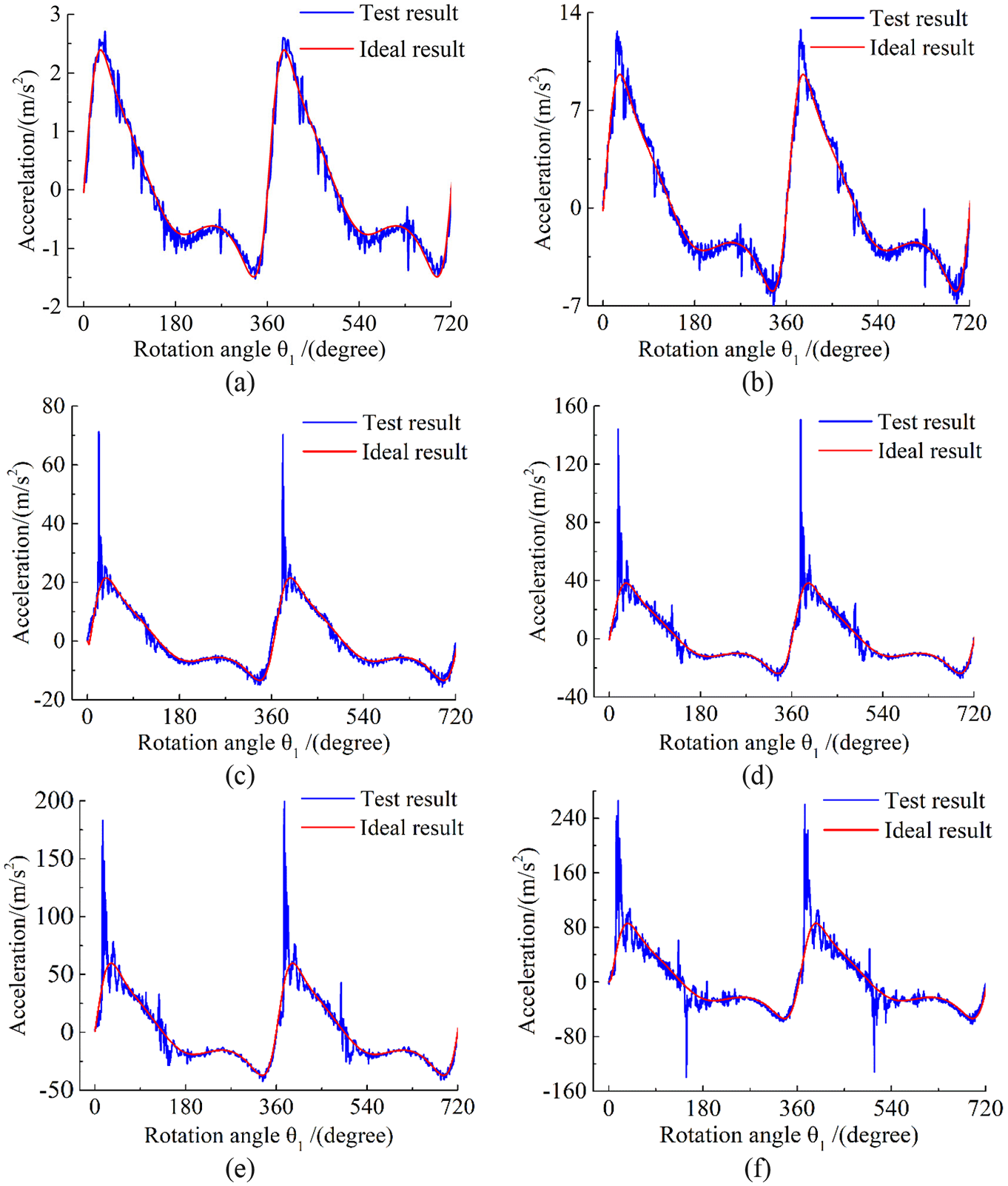
Acceleration responses for different driving speeds: (a) 60 rpm, (b) 120 rpm, (c) 180 rpm, (d) 240 rpm, (e) 300 rpm, and (f) 360 rpm.
As shown in Figure 4, the experimental acceleration results are compared with that obtained through the second derivative of equation (2) with respect to time. Obvious oscillations emerge in the acceleration curves from the experiment, which suggests that the movement of slider is unstable, and vibration effects are also contained in the presence of joint clearance. Besides, with increasing driving speed, the vibration is more severe, and some transient vibration impacts are activated in specific positions. For example, as the driving speed increases to more than 180 rpm, the first excited dynamic transient impact (first impact) appeared periodically in the mechanism when it moves to θ1 = 36° + n×360°,where the slider part moves to its limit positions, maximum acceleration is reached and then its velocity keep increasing yet with decreasing acceleration. The amplitude increases from 70 to 260 m/s2 with the rise of the driving speed from 180 rpm in Figure 4(c) to 360 rpm in Figure 4(f). Meanwhile, the second excited dynamic transient impact (second impact) with an amplitude of 130 m/s2 appears at position θ1 = 150° + n × 360°, where the slider part moves to its zero acceleration position. It means the slider part reaches its maximum positive speed. After that it would slow down to zero, and then move backwards. Under the 360 rpm driving speed. These transient impacts demonstrate large impact forces in the clearance joint, which could reduce the service life of the whole multi-link articulated mechanism. Similar to the crank-slider and the four-bar mechanism, the experimental results of the clearance of 0.1 mm under different driving speeds indicate that clear vibration responses in high driving speeds are introduced by a joint clearance. Also, as the driving speed rises, the dynamic responses tend to be more sensitive and deteriorated more dramatically by clearance joints, which can be also found in recent study on a multi-link mechanism. 20 Besides, two impacts will appear successively and feature periodicity during the movement. This indicates that for multi-link articulated mechanism with clearance joint, these impacts only emerge at specific positions.
Effects of joint clearance sizes
In the service of mechanism system, the joint clearance size would be increased by the wear effects and eventually further deteriorate the dynamic responses. 39 Investigation of the cases of greater clearance size is necessary. Relative experimental results with 0.2- and 0.4-mm joints clearance at the driving speed of 240 rpm are given as Figure 5.

Acceleration responses with different clearance size: (a) 0.2 mm and (b) 0.4 mm.
From a dimensionless point of view, these transient impact amplitude are well comparable to the study of Bai et al. 40 For detailed analysis, the acceleration responses for one full crank rotations are divided into six stages. Firstly, at point a, the sign of acceleration changes from negative to positive, which means that the movement mechanism transforms from deceleration to acceleration and reversed contact force in clearance joint. In that case, the journal would separate from the bushing, enters into free flight which breaks the kinematic chain of the multi-link articulated mechanism. Therefore, in stage a-b, the mechanism would keep its original movement state and its acceleration value is maintained near zero. At point b, the journal contact with the bushing surface on the other side, and the kinematic chain is rebuilt again. However, as the relative velocity between journal and bushing would accumulate in the free flight stage a-b, once the journal contacts the bushing surface, maximum penetration depth occurs between the journal and bushing. Thus, intense transient impact and obvious oscillations occur in stage b-c. The transient impact value in stage b-c is 240 and 350 m/s2 with joint clearance of 0.2 and 0.4 mm, respectively, higher than that of 0.1 mm in Figure 4(d) (150 m/s2). As the oscillations decay in stage b-c, the movement tends to stabilize gradually in stage c-d. Then continuous-contact state between the journal and bushing is detected. In this motion period, slight oscillations mean no clear impact force between the journal and the bushing, so the experimental and analytical results coincide. On the other hand, as the movement change from acceleration to deceleration at point d, the journal would separate with the bushing again, the short-term free flight stage d-e occur. Afterward, similar to stage b-c and c-d, transient penetration and continuous-contact state can be detected from the experimental results in stage e-f and f-g. The invisible second impact in previous Figure 4(d) emerges and increases from 115 to 200 m/s2 with the increase of the joint clearance size from 0.2 to 0.4 mm at 240 rpm driving speed. This indicates that increased joint clearance size prompts the appearance of the transient dynamic impact of the mechanical system. With the effects of clearance joints, free flight, penetration and continuous-contact motion states between the busing and journal in clearance joint, as well as certain sequence between them can be observed. Similar periodic motion state alternation caused by clearance joint can also be found in Flores’s study on the slider acceleration output and joint reaction force responses of a slider-crank mechanism with two joints of 0.05 mm clearance size. 40 Additionally, compared with Figure 5(a), the free flight motion state of the 0.4 mm joint clearance in Figure 5(b) lasts longer. It can be reasonably inferred that a larger clearance permits the journal to move in a larger free space. Thus, more kinetic energy is accumulated, which results in deeper penetration and more severe impact.
Effects of joint clearance number and position
Compared with simple four-bar and crank-slider mechanisms, there is more joint clearance in the multi-body articulated mechanism. From the sensitivity analysis point of view, these clearance joints might make different contribution to the dynamic responses of the mechanism. Taking the mechanism system with one 0.4 mm clearance joint with a 240 rpm driving speed as an example, the experimental results are given in Figure 6.

Acceleration responses with different joint clearance number and position: (a) clearance joint A, (b) clearance joint B, (c) clearance joint c, (d) clearance joint A and B, (e) clearance joint B and C, and (f) clearance joint A and C.
Compared with Figure 5, the impact amplitudes in Figure 6(a) and (b) decrease dramatically with the decrease in the number of clearance joints. However, for the one clearance joint case presented in Figure 6(c), the first impact value caused by clearance joint C is still as high as 265 m/s2. As for the two clearance joint experiment result, once the clearance joint C exists, greater impact can be detect in Figure 6(e) and (f) than Figure 6(d). These prove that the clearance joint in different positions exerts variable degrees of influence on the dynamic responses of the mechanism. Under the same clearance size and driving speed, the clearance joints at the end of the transmission chain have greater effects on the mechanism. From a perspective of the damping effect of parts’ flexibility, the vibration energy caused by joint A or B must transmit throughout the links in the transmission chain before the dynamic output of the final slider. In that process, some vibration energy is dissipated by the damping effect of the flexible links in the mechanism system. Therefore, the stimulated vibration amplitude in the acceleration output by the front clearance joint of the drive chain is reduced significantly. It suggests that the dynamic responses of the mechanism system are more sensitive to the joint clearance at the end of the transmission chain of the mechanism system, thus a higher tolerance fit should be utilized to control the clearance size. Meanwhile, for the multi-body articulated mechanism in this study, acceleration impact occurs at a particular position of the mechanism. Therefore, the relative vibration reduction method should be considered in these positions during the design process of this kind of multiple articulated mechanism system. From a practical point of view, these impact amplitudes quantifying analysis under different clearance joint scenarios provides optimization design suggestion for multi-link articulated mechanism system.
Effect of flexible sleeves
Based on the abovementioned experimental studies, transient impacts occur due to the existence of clearance joint. These impacts can cause the deteriorated dynamic responses and reduced service life of the mechanism. Since the vibration energy introduced by clearance joint is dissipated by the damping effect of flexible components, flexible parts in the articulated mechanism can compensate for the undesired effects of the clearance joint to some extent. 26 On the other hand, whole flexible parts can also greatly increase the system flexibility which decreased the moving accuracy of the mechanism. For better utilization of the damping effect of parts flexibility and avoiding the following accuracy loss, rubber sleeves with a thickness of 2 mm are added between the journal and bushing in the clearance joint to optimize the dynamic responses of the mechanical system. Figure 7 gives the experimental results of three clearance joints of 0.1 mm with and without rubber sleeves under the driving speeds of 180, 240, 300, and 360 rpm.
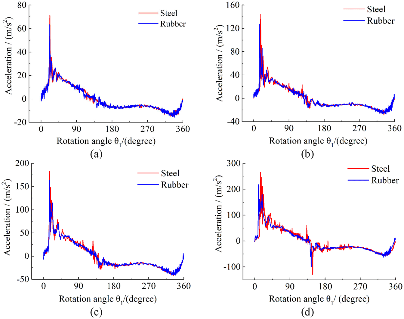
Acceleration responses with rubber sleeves: (a) 180 rpm, (b) 240 rpm, (c) 300 rpm, and (d) 360 rpm.
According to Figure 7, the transient impacts decrease dramatically with the utilization of rubber sleeves between the adjacent bushing and journal. Also, the oscillations in the acceleration response are weakened, and more stable acceleration responses are obtained especially for the case of the higher driving speed of Figure 7(d). Taking the transient impact at position θ1 = 36° + n × 360° as an example, the detailed results by three cases are listed in Table 2.
Reduction percentage of the first impact value.

According to Table 2, the rubber sleeves can dissipate the vibration energy caused by penetration between the adjacent journal and bushing in the clearance joint. Thus, the undesired transient impact is reduced and the dynamic responses of the multi-link articulated mechanism are optimized. Besides, more obvious optimization results can be obtained as the driving speed rises. Experimental investigations in this paper reveal that the negative effects of joint clearance are suppressed by flexible rubber sleeves. Further investigations on dynamic response optimization based on different sleeve material and thickness will be implemented in future work.
Conclusions
The effects of joint clearance on the dynamic responses of a multi-link articulated mechanism were analyzed in detail in the work. Limited to the theoretical modeling and solution complexity of the dynamic system with multiple clearances, experimental investigations method were highlighted and a test rig was constructed for that purpose. The main contribution can be summarized as follow: (1) Planar multi-link mechanisms with multiple clearance is study experimentally, and the effects of driving speed, joint clearance size, clearance number and positions on the dynamic responses of the mechanism in different experimental scenarios is analyzed comparatively. Two periodic impacts at specific positions, as well as the sequence of free flight, penetration and continuous-contact motion states in clearance joint, are observed in the acceleration outputs of the mechanism system. Additionally, the impact amplitude would rise with the increase of driving speed and clearance size. (2) Flexible sleeves are first set to the adjacent parts to decrease the negative effects of transient impact introduced by joint clearance. Comparative analysis indicates that the flexible sleeves can dissipate the vibration energy caused by the penetration of the journal and bushing in the clearance joint. Thus, the value of transient impacts decreases dramatically. This is an ongoing study on the dynamic optimization by flexible sleeves in clearance joint for multiple link articulated mechanism. Last but not least, there are rich research content for multi-link mechanisms with multiple clearances, this paper can provide a basis for the follow-up mechanism.
Footnotes
Handling Editor: James Baldwin
Declaration of conflicting interests
The author(s) declared no potential conflicts of interest with respect to the research, authorship, and/or publication of this article.
Funding
The author(s) disclosed receipt of the following financial support for the research, authorship, and/or publication of this article: We have received funds for covering the costs to publish in open access. This research was supported by the National Science Foundation of China (No. 51705372), National Science and Technology project of the power grid (Grant No. 5211DS16002L), and Jiangsu Provincial Natural Science Foundation of China (No. BK20170411).
Data availability
We promise the experiment and simulation data in Figures 4 to 7 used to support the findings of this study are fully available from the corresponding author upon request. Any original date requests are welcome, please contact