
Abstract
Improving the quality of surface molds after electrical discharge machining is still being considered by many researchers. Powder-mixed dielectric in electrical discharge machining showed that it is one of the processing methods with high efficiency. This article reports on the results of surface quality of mold steels after powder-mixed electrical discharge machining using titanium powder in fine machining. The process parameters such as electrode material, workpiece material, electrode polarity, pulse on-time, pulse off-time, current, and titanium powder concentration were considered in the research. These materials are most commonly used with die-sinking electrical discharge machining in the manufacture of molds and has been selected as the subject of research: workpiece materials were SKD61, SKT4, and SKD11 mold steels, and electrode materials were copper and graphite. Taguchi’s method is used to design experiments. The influence of the parameters on surface roughness was evaluated through the average value and ratio (S/N). Results showed that the parameters such as electrical current, electrode material, pulse on-time, electrode polarity, and interaction between the electrode materials with concentration powder mostly influence surface roughness and surface roughness at optimal parameters SRopt = 1.73 ± 0.39 µm. Analysis of the surface layer after powder-mixed electrical discharge machining using titanium powder in optimal conditions has shown that the white layer with more uniform thickness and increased hardness (≈861.0 HV), and amount and size of microscopic cracks, is reduced. This significantly leads to the increase in the quality of the surface layer.
Introduction
Electrical discharge machining (EDM) is a method most commonly used for the fabrication of surface molds. This method has no binding of hardness between workpiece and tools; problems such as vibration, mechanical stress, and noise do not appear during the processing. 1 However, machining by EDM with low machining productivity and machining surface quality is not high and this leads to increased manufacturing costs. 2 A large number of parameters of this technology and machining mechanism are unclear, and process optimization always requires exact values of the process parameters. And this has caused many difficulties in research on EDM and powder-mixed electrical discharge machining (PMEDM).
Mixing Cu, Si, and Al powders in dielectric fluid reduces the dielectric strength of the dielectric fluid. 3 Increased concentration of the powder will lead to increased productivity and quality of the machining surface. Mixing Si powder into the dielectric fluid in EDM with positive electrode polarity reduces the surface roughness (SR).4–7 However, for highly efficient machining processes, short-time electrical discharges and even distribution of the powder particles in the dielectric fluid are required. In the same processing conditions, Al and Gr powders will give the undulating surface machining smaller than Si powder. 8 The depth of the crater of surface machining using SiC powder was larger than Al powder, and this increases the undulating surfaces than EDM. 9 The average-sized powders (Si, Gr, Mol, Al, SiC) mixed into the dielectric of EDM fluid showed that the Al powder surface gloss of SKH-51 steel is higher than SKH-54 steel. 10 With small concentrations of Gr powder (2 mg/L), low flow can create Ra = 0.0931 µm of SKH-51 steel. 11 Powders with smaller size will increase the density of the powder in the dielectric fluid, and this leads to increased frequency of the discharge bridge and more uniform distribution of the sparks, so part of the surface quality will be the higher. 12 Using the additive powder mixed into the dielectric fluid increases the separation of the beads, resulting in even dispersion of the beads in the dielectric fluid. 13 This not only improves the undulating surface but also reduces the thickness of the white layer on the surface of the workpiece. To create machining surface with Rmax = 5 µm by EDM requires 5 h, while by PMEDM requires only 25 min using powder Al. 14 Thus, the powder mixed into the dielectric fluid made significant improvements to the topography and SR of the machining surface. PMEDM has a lot of process parameters, which create a lot of difficulties in modeling and optimization of this field. Using the Taguchi’s method to optimize the process parameters of PMEDM shows that material removal rate (MRR) and Ra were significantly improved compared to EDM. 15 The concentration of powder, current, and pulse on-time are the process parameters that strongly influenced MRR and Ra. MRR, T, and Ra are selected targets to optimize in many studies.16–18 Studies on PMEDM show that this approach has resulted in productivity and quality processes.1,19,20 However, studies of materials, dimensions, characteristics of powder mixed into the dielectric fluid, and machining principle of the method still need further PMEDM investigation. 21 Taguchi’s method is widely used in research on EDM and PMEDM. 22
This study will investigate the influence of parameters such as electrode materials, current, pulse on-time, pulse off-time, electrode polarity, titanium powder concentration, the interaction between the electrode material and machining materials, interactions between materials and concentration of powder machining, and interaction between the electrode material and the concentration of the powder to SR of steel dies in fine machining by EDM method. SKD61, SKD11, and SKT4 mold steels are very popular steels used in the manufacture of hot die of cold stamping and were used in this study. The results showed that titanium powder mixed into the dielectric fluid has decreased the SR in fine machining by EDM significantly. And, after PMEDM using titanium powder, the surface quality has been increased significantly. This is an important prerequisite for improving the processing efficiency of PMEDM using titanium powder in the manufacture of surface molds.
Experimental procedure
Experimental equipment
Experiments were conducted using a die-sinking EDM platform, a model, AG40L CNC, from Sodick, Inc., Schaumburg, IL, USA. The materials used for workpiece were SKD61, SKD11, and SKT4 (Japanese Industrial Standard) die steels that are used extensively for forged dies. The workpiece dimension was 100 mm × 80 mm × 25 mm. Experimental diagram and equipment in the dielectric fluid container are shown in Figure 1. Case of steel CT3 (GOST 380-88), with 3-mm thickness, size 330 mm × 180 mm × 320 mm with a capacity of 8.5 L; two stirring vanes (Φ120) rotating at a speed of 100 r/min; A303 pump with nozzle (Φ8) used to supply dielectric fluid mixing powder with stable flow (24 L/min) at discharge openings; and permanent magnet with swarf suction machining tasks are used in this study.Ti is the ferrous metal with a specific weight lighter than steels 40% and heavier than 60% Al, good electrical conductivity and nonmagnetic so in this research were selected Ti powder (45 µm). The tool materials selected for this investigation were graphite (Gr) and copper (Cu). Cu and Gr have excellent electrical and thermal conductivity and are major commercial materials.

Schematic line diagram (1: stirring; 2: machining tank; 3: electrode).
The following material parameters were studied during the course of this experiment: microstructure, surface hardness, SR, and surface appearance. Three readings were taken for each work specimen to compute the final, average measurement. SR was measured using an SJ-301 from Mitutoyo, Sakado, Japan. After EDM, the samples were cleaned and a cross-section of die-sink surface machined was taken. An optical microscope was used to study the change in the microstructure of the surface after EDM. The rest of the analysis was carried out on six samples using a scanning electron microscope (SEM, model JSM 6490; JEOL, Tokyo, Japan). Microhardness was measured on a microhardness tester (model Indenta Met 1106) from Buehler, IL, USA.
Experimental design method
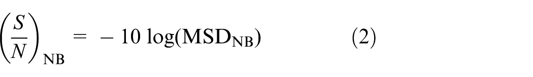
The overall objective was to create a product with the highest quality and lowest price. These methods were based on traditional experimental design, following the Taguchi’s method, which can examine the influence of process parameters, specific to the quality of the production process and cost. There are many orthogonal arrays available in Taguchi’s method; therefore, selection depended on the number of factors and degrees of freedom of each factor. In this study, seven main factors were considered, out of which, two factors were at two levels, each having 1 degree of freedom. Five of the main factors had three levels, with each having 2 degrees of freedom. In this study, the following interaction terms were considered, specifically, workpiece material, x-electrode material (A × B), x-powder concentration (A × G), and electrode material x-powder concentration (B × G). Also, the study considered three interaction terms, as shown in Table 1. Thus, the total sum of degrees of freedom, including the main factors as well as the interaction terms, was 20. Therefore, based on the 20 degrees of freedom, the L27 orthogonal array suited the present requirements as it had 26 degrees of freedom. The remaining 6 degrees of freedom were assigned as random error. The analysis of variance (ANOVA) was based on data obtained from Taguchi’s experimental design and was used to select new parameter values to optimize the quality characteristics. Data from the table were analyzed using charts, pictures, ANOVA, and Fisher’s ratio test (F). To analyze the results of experiments, Taguchi used a ratio, S/N, to evaluate the impact of interference. The S/N ratio was calculated to determine the effects of these parameters and their interactions to the quality characteristics in processing.
Input parameters and their levels.

DOF: degree of freedom.
Dummy treated.
The higher, the better

where
In this case,
The normal, the best
where
In this expression,
The lower, the better

where
In this equation,
Data from the table were analyzed using charts, pictures, ANOVA, and Fisher’s ratio test (F). F value is defined as
where MS is the mean square.
Results and discussion
Experimental results
Results of machining SR are evaluated by the value of SR. Each experiment was repeated three times. Minitab software is currently being used very commonly to analyze experimental results. The results are processed using Minitab 17 to determine the average value of SR and ratio S/N. The results are shown in Table 2.
Results for surface roughness (Ra).

Dummy treated.
Effects of parameters and interaction between process parameters on SR
ANOVA average value of SR
ANOVA for surface roughness.

DOF: degree of freedom.
Figures 2 and 3 show the influence of the parameters and a number of interactions between the parameters to SR of surface machining by PMEDM using Ti powder.
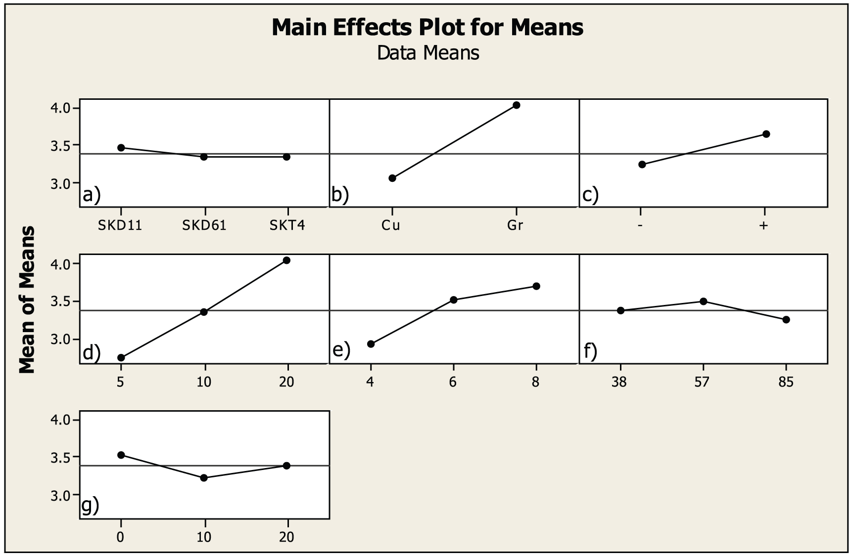
Main effects plot for mean surface roughness (a) workpiece material; (b) electrode material; (c) electrode polarity;(d) pulse-on time (μs); (e) current (A); (f) pulse-off time (μs); and (g) powder concentration.

Interaction plot for mean surface roughness.
The results show that the SKD11 steel surface after machining will have the largest SR, and the SR of SKD61 steel and SKT4 steel is equal (Figure 2(a)). The reason is that the melting temperature and evaporation of SKD11 steel (1370°C) are lesser than those of SKD61 steel (1454°C) and SKT4 steel (1510°C), and the electrical resistivity of SKD11 steel is also lesser than SKD61 and SKT4. This led to the thermal energy of the sparks; steel SKD11 melted and evaporated faster and more than SKD61 and SKT4 steels. The results showed that SKD61 steel had the strongest influence to SR and smallest impact with SKD11 steel (Figure 3(a)). Powder concentration increase led to roughened surface of SKD61 and continued to fall, but continued to increase with SKT4 steel (Figure 3(b)). Powder concentration increase (0/10 g/L) led to SR of SKD11 steel and continued to rise sharply, but higher powder concentration slightly increased SR, but decreased when there is no powder. Powder concentration increase (10/20 g/L) led to SR of SKD61 steel, and continued to reduce, but higher powder concentration increased SR in SKD11 and SKT4 steels.
SR of machining surface after PMEDM with electrode Gr was greater than electrode Cu (Figure 2(b)). It is caused by the processing capacity of PMEDM, with Gr electrode higher than Cu electrode and it leads to larger size and depth of the crater surface machining with Gr electrode. SKD11 steel gives smallest SR with Cu electrode and largest SR with Gr electrode (Figure 3(c)). In SKD61 steel and SKT4 steel, the degree of impact and results of SR are similar to the second electrode material. The surface processed by Cu with Ti powder mixed into the dielectric fluid shows lesser SR than the smallest with no powder and powder concentration of 20 g/L (Figure 3(d)). In contrast, Gr electrode greatly reduced in powder concentration of 10 g/L, but increased with greater levels of powder concentration. SR of machining surface after EDM with Gr electrode was much greater than Cu electrode.
SR of machining surface in PMEDM with positive electrode polarity was larger than the negative electrode polarity (Figure 2(c)). This is because the processing capacity of EDM with positive electrode polarity was higher than negative electrode polarity, and it led to increase in the diameter and depth of the crater surface machining and hence increase in the SR. MRR of PMEDM with positive electrode polarity is higher than PMEDM with negative electrode polarity, and it may be due to the Ti powder, pulse on-time, and pulse off-time which caused ions energy higher than the energy of the electrons, but this has not been clearly explained. Increase in SR is proportional to the increase in the pulse on-time (Figure 2(d)). Increased processing capacity results in increased SR, and SR is the largest at pulse on-time 20 µs. Increased current led to the increase in SR (Figure 2(e)). The reason is that the energy of the sparks raised as the current increases which led to increase in MRR and SR. Pulse off-time 38 and 85 µs gives small SR values (Figure 2(f)). This may be due to the reduction in the size of the dimples on the surface by the processing power. The largest SR is obtained with pulse off-time 57 and 85 µs.
Titanium powder mixed into the dielectric fluid reduces SR (Figure 2(g)). This may be due to the energy of the sparks, making the dimples with a diameter and depth smaller in the surface machining. When there is no powder in the dielectric fluid, SKT4 steel had the smallest SR, while SKD61 steel and SKT4 steel had equal value of SR (Figure 3(e)). With powder concentration of 10 g/L, SR was the smallest with SKD11 steel and highest with SKT4 steel. With powder concentration of 20 g/L, SR of SKT4 steel was the largest and of SKD61 steel was the smallest (Figure 3(f)). Smallest value of SR was obtained with Cu and the largest with Gr at powder concentration of 20 g/L. As such, the SR greatly reduced when the powder was mixed into the dielectric fluid, and with SKT4 steel, after EDM, electrode with Cu in the dielectric fluid with powder concentration of 20 g/L gave the smallest Ra. This significantly enhanced surface quality machining and reduced the time of polishing materials.
Figures 4–9 illustrate the response of SR, and the process parameters considered for the analysis are current, pulse on-time, pulse off-time, and concentration of Ti powder. Figure 4 shows the variation of SR with respect to current and concentration of titanium powder. When the current is increased from 4 to 8 A, there is no change in the SR values at powder concentration of 0 g/L. It may be due to less change in the spark energy. When powder concentration is increased to 10 g/L, minimum SR value was achieved at 6 A of current and maximum SR value was obtained at 8 A of current. At 20 g/L, the minimum SR was obtained at current 4 A and maximum SR was obtained at current 6 A. SR is most affected by the change in the powder concentration and is significantly affected at powder concentration of 10 g/L. Figure 5 shows the variation of SR with respect to powder concentration and pulse on-time. It was found that SR increases with increase in pulse on-time from 5 to 20 µs. SR was the smallest with powder concentration of 10 g/L and pulse on-time 10 µs, and SR was obtained largest with pulse on-time 20 µs. SR was not affected when the powder concentration of 0 g/L was used. Response of SR was more at titanium powder concentration of 20 g/L and pulse on-time 5 µs. Figure 6 shows the variation of SR with respect to concentration of powder and pulse off-time and there was no effect of pulse off-time on SR. Minimum value of SR was obtained at powder concentration of 10 g/L and pulse off-time of 38 µs, and maximum value of SR was obtained at powder concentration of 20 g/L and pulse off-time of 38 µs.

Response surface of SR versus current and powder concentration.

Response surface of SR versus powder concentration and pulse on-time.

Response surface of SR versus powder concentration and pulse off-time.
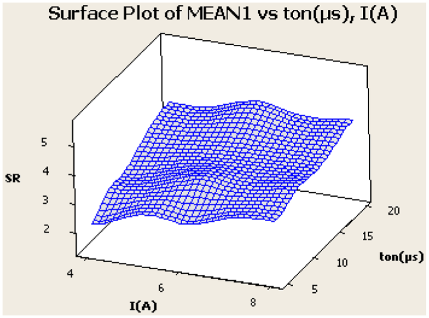
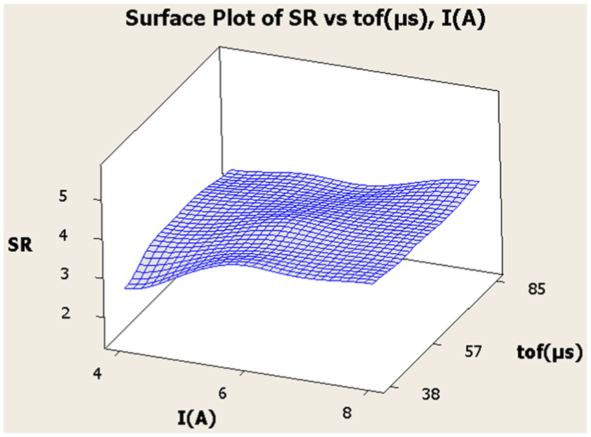
Response surface of SR versus current and pulse on-time.
Response surface of SR versus current and pulse off-time.
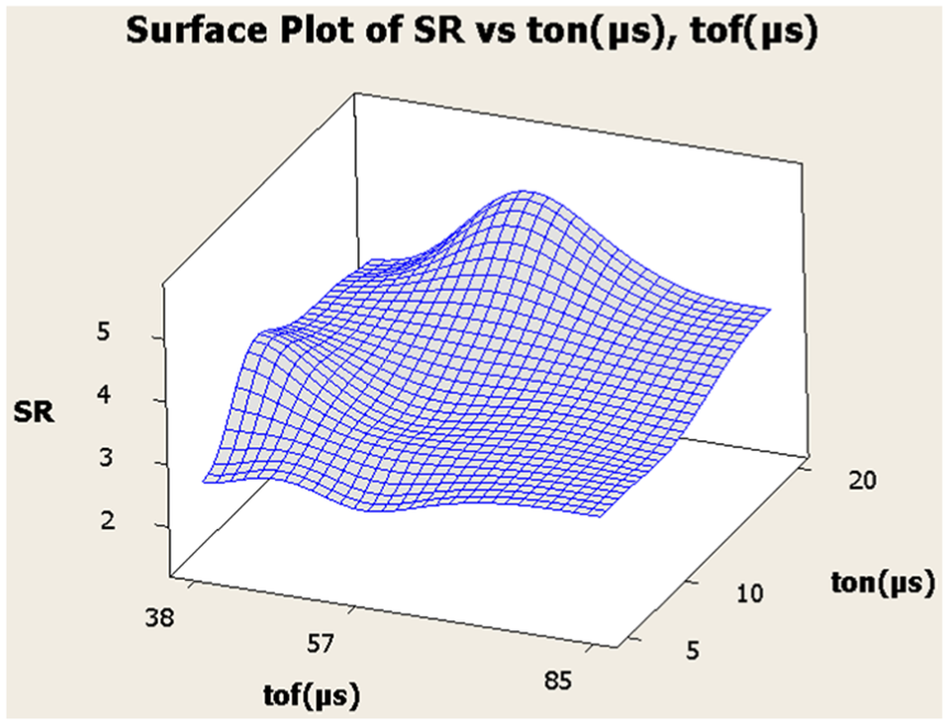
Response surface of SR versus pulse off-time and pulse on-time.
Figure 7 shows the variation of SR with respect to current and the pulse on-time. Figure 8 shows the variation of SR with respect to current and pulse off-time and found less influence on SR. Minimum SR was obtained at current of 4 A, pulse on-time of 5 µs, and pulse off-time of 38 µs. SR increases with increase in current, pulse on-time, and pulse off-time. This is due to the increase in spark energy; however, this increase is not large. Maximum SR was observed at current of 8 A, pulse on-time of 20 µs, and pulse off-time of 85 µs. Figure 9 shows the variation of SR with respect to pulse on-time and pulse off-time. SR is greatly influenced by interaction of pulse on-time and pulse off-time. Maximum SR was obtained at pulse on-time of 20 µs and pulse off-time of 57 µs. Minimum SR was obtained at pulse on-time of 38 µs and pulse off-time of 5 µs.
Optimization parameters of SR
Results of ANOVA S/N ratio of SR in Table 3 show that the electrode material (F = 55.47), the polarized electrodes (F = 15.1), pulse on-time (F = 35.72), output current power (F = 20.97), and the interaction between material processing with powder concentration (F = 18.12) are parameters that influence the S/N ratio of SR. The remaining parameters produced a weak influence on the S/N ratio of SR. Electrode materials are the most influential parameters and the time to stop pulse generator is the most essential parameter influencing S/N ratio of SR.
The greater S/N ratio showed that the research results were less affected by noise. The S/N ratio value for Ra was affected by the parameters shown in Figure 10. The results showed that the steel materials, SKT4 steel (A3), the Cu electrode material (B1), the negative electric polarity (C1), with a pulse duration of 5 µs (D1), the current flow of 4 A (E1), a pulse off-time 85 µs (F3), and a titanium powder concentration of 10 g/L (G2) positively influenced the S/N ratio for Ra. These process parameters decreased the degree to which the Ra was affected by the noise and consequently resulted in most optimal value for Ra with the least amount of alteration. The image shown in Figure 11 demonstrates the influence of the interaction between the parameters to S/N ratio for Ra. The results indicated that the interactions between the SKT4 steel and the Cu electrode materials (A3 × B1), the interactions between the SKD61 steel and the titanium powder concentration of 20 g/L (A1 × G3), and the interactions between the Cu electrode materials and the titanium powder concentration of 20 g/L (B1 × G3) included the pairs of interactions that influenced the S/N ratios for Ra.

Main effects plot for S/N of SR.

Interaction plot for S/N of SR.
Estimated value of
under optimal conditions
Process parameters for Ra included the following: A1, B1, C1, D1, E1, F2, and G2. The electrode material (B), the electrode polarity (C), the pulse on-time, and the current (E) had strong influences on Ra. Therefore, the Ra value was determined by the formula (5)

In this expression,
The confirmation experiments were conducted where the process parameters were determined through calculations of the SKD61 steel workpiece material, Cu electrode, negative electrode polarity, pulse on-time of 5 µs, current 4 A, pulse off-time 85 µs, and powder concentration of 10 g/L. The result of SR = 1.47 µm demonstrated high accuracy, with discrepancies between the calculated and experimental results of 1.5%.
Topography of the machined surface at optimization parameters
Assuming that each spark leads to the formation of a spherical crater on the surface of the workpiece, the volume of metal removed per crater will be proportional to the cube of the crater depth. The surface accumulated many large craters created by the sparks generated during the pulse cycle, as shown in Figure 12. The craters were on the radius of curvature created when the melting and evaporating materials affected by the dielectric fluid were simultaneously quenched and caused the outer surface tension. Topography of surface machining is considered good if the crater contains a small depth and if it is evenly distributed. The depth of the crater on the surface depends essentially on the energy of the sparks: high-energy sparks will create the crater with large depth which leads to increased SR. To the crater with a smaller size, the power of the spark must be smaller with shorter pulse on-time. Figure 13 shows that the quality of surface machining significantly improved in optimal conditions. The number of craters increased, but the diameter and depth decreased. This is because the powder mixed into the dielectric fluid increased the quantity of the sparks and led to the energy of the dispersed sparks. Therefore, topographies improved the quality.

Topography of the surface after EDM: (a) A1, B1, C1, D1, E3, F1, and G1 and (b) optimization parameters.

The morphology of the debris particles produced during EDM: (a) A1, B1, C1, D1, E3, F1, and G1 and (b) optimization parameters.
Many small hard particles and microscopic cracks appeared on the processed surface and adhered to it, causing an increase in the SR and thus reducing the fatigue strength of the surface layer (Figures 13 and 14). These spherical protrusions are particles of molten metal that were expelled from molten workpiece and powder, and small amounts of electrode material form spheres during the discharge and later spattered and solidified on the workpiece surface. The particles were formed as a result of the removal of the molten metal and must have solidified at an extremely high rate. Otherwise, the surface tension of the molten metal would have rounded off the sharp edges. The cracks were formed with the result of the high thermal stresses prevailing at the specimen surface, as the latter was cooled at fast rate after the discharge process. The number of microscopic cracks and debris particles has been reduced due to powder mixed into the dielectric fluid in EDM. Negative electrode polarity creates machining surface with smaller number of microscopic cracks than positive electrode polarity. The cracks with largest size was obtained at 8 A current, when no powder was mixed into the dielectric fluid in EDM with electrode Gr (+), and when the current increases, the size of the cracks increases. Ti powder is mixed into the dielectric fluid in EDM, which has made the processing surface topographies with good quality and the number of cracks and microscopic debris particles on the surface adhesion is reduced.

Cracks on surfaces after EDM: (a) A1, B1, C1, D1, E3, F1, and G1 and (b) optimization parameters.
Cross-sectional analysis following EDM at optimization parameters
The cross-sectional structure of the SKD61 steel surface fabricated using EDM with both A1, B1, C1, D1, E3, F1, and G1 and optimization parameters exhibited three layers, as shown in Figure 15: the white layer, the heat-affected zone (HAZ), and the base metal. The white layer was the outermost layer, light-colored, with a relatively high thickness: 9.22–19.18 µm for A1, B1, C1, D1, E3, F1, and G1 and 13.43–17.61 µm for optimization parameters and is distinct from the other layers. This layer forms when some of the molten material (from both the electrodes, Ti powder, and workpiece) is not removed and is rapidly quenched by dielectric fluid. The white layer contains a high density of microscopic cracks that run across the total depth of it, only seldom continuing into the layers beneath. The cracks are mostly perpendicular to the surface of the workpiece. The larger size of the microscopic cracks in the die steel are produced using A1, B1, C1, D1, E3, F1, and G1 compared to that produced using optimization parameters.

The different layers formed on the surface after EDM: (a) A1, B1, C1, D1, E3, F1, and G1 and (b) optimization parameters.
The microhardness of the white layer in both types of specimens was very different: 506.7 HV for A1, B1, C1, D1, E3, F1, and G1 and 861.0 HV for optimization parameters. SKD61 hot-die steel is used extensively for hot-forged dies. Forging dies and hot-mold dies always operate in high-temperature environments and under high-shock pressure. Choosing the correct type and hardness of the die material and the surface layer coating is very important for improving the working accuracy and functionality of the dies. Given the above results, the presence of the white layer in EDM reduces the working capacity of hot-die sinks. In contrast, the white layer of surface machining by PMEDM using Ti powder increased the durability of the mold significantly. The HAZ was located beneath the white layer and was difficult to observe clearly. It was not as thick as the white layer. In this layer, the material has been heated below the melting point of the material as in the recast layer. There were a few microscopic cracks with small depths in the HAZ layer that were not parallel to the machined surface. The microhardness of the HAZ was very high (≈648.13 HV); these values were higher than that of the white layer in EDM and the base metal. The properties of the HAZ may alter the performance of the hot-forging die. As such, the quality of the surface layer after PMEDM using Ti powder has improved significantly.
Conclusion
Research has shown that titanium powder mixed into the dielectric fluid in EDM has improved surface quality of fine machining. Electrode materials are the most powerful influence parameters with 21.8% total influence to SR. The duration of the pulse parameters, current, electrode polarity, and the interaction between the materials processed with flour concentrations also influenced the SR with the impact 29.35%, 11.76%, 3.35%, and 22.6%, respectively. The remaining parameters and interactions weakly influence SR. Ti powder in the dielectric fluid reduced SR; whereas, when there is no flour dough, the SR decreased: 11.3% with powder concentration of 10 g/L and 3.08% at a concentration of 20 g/L. SR of Gr electrode is about 31.7% greater than Cu electrode. Negative electrode polarity will decrease 5.2% SR compared to positive electrode.
Electrode materials, electrode polarity, pulse on-time, current, and interaction between the workpiece material with starch concentrations have a strong influence on S/N ratio of SR. SRopt = 1.73 ± 0.39 µm with 90% confidence interval is determined by the following process parameters: SKD61 steel, Cu electrode, negative electrode polarity, pulse on-time of 5 µs, current of 4 A, pulse off-time of 85 µs, and powder concentration of 10 g/L. Empirical tests show that the model can quite accurately calculate the predicted SR. PMEDM for SR is smaller than the largest EDM with 31.7% reduction. SKD61 steel will have SRmin with cathode electrode isomers and powder concentration of 10 g/L.
The quality of the surface after EDM with titanium powder mixed into the dielectric fluid was increased by reducing the SR and thus improving the mechanical properties and topography of the surface layer. Thickness increased the durability of the mold and work capacity also increased significantly (white layer and HAZ). This has increased the efficiency of EDM in mold machining. However, further research is needed on the mechanical properties, alloy composition, and the microstructure of the surface layer, from which a comprehensive evaluation of the effectiveness with titanium powder mixed into the dielectric fluid can be obtained.
Footnotes
Academic Editor: Noel Brunetiere
Declaration of conflicting interests
The author(s) declared no potential conflicts of interest with respect to the research, authorship, and/or publication of this article.
Funding
The author(s) received no financial support for the research, authorship, and/or publication of this article.