
Abstract
Curve-face gear drive is a new type of variable transmission ratio gear pair between the intersecting axes based on the face gear pair. And tooth width is one of the main geometrical factors of curve-face gear which affects the intensity of tooth root. This article uses the method of boundary function and geometric approximate evaluation to investigate the undercutting and pointing conditions of curve-face gear considering the tooth profile difference. The equations of tooth profile distribution angle and engagement angle are derived using the coordinate transformation theory. On this basis, the equations of the theoretic undercutting and pointing conditions are deduced, and the undercutting inner diameter and pointing outer diameter of the tooth profile are simulated using mathematical software. Then, the corresponding phenomenon of undercutting and pointing of curve-face gear are analyzed. In the end, the feasibility of the theoretical calculation is received by the experiment of curve-face gear.
Introduction
Curve-face gear pair is a new type of variable transmission ratio drive between the intersecting axes, which combines the common transmission characteristics of non-cylindrical gear, bevel gear, and face gear. It can be used in engineering machinery, variable pump, bio-simulation machine, and so on. So the research on the curve-face gear is particularly important. Tooth width is one of the main geometrical factors of curve-face gear which affects the intensity of tooth root. In the inner diameter of curve-face gear, due to the existence of the undercut boundary line, it limits the inner diameter of the face gear; and in its outer diameter, addendum thickness decreases due to the constraint of constant-height tooth, which results in the intersection of the tooth surface. So the undercutting and pointing phenomenon of tooth profile limit the tooth width of face gear. 1 As a special type of face gear, the tooth width of the curve-face gear is also limited by the phenomenon. 2
In the process of solving tooth profile of non-circular gear, it needs to deduce large numbers of formulas and solve non-linear equations. Therefore, the research on tooth root of non-circular gear is less. For non-circular gear, (1) an approximate calculation to calculate the maximum module of non-circular gear avoiding undercutting according to the minimum radius of curvature of pitch curve was provided.3,4 However, this method did not concern the tooth profiles difference of non-circular gear. (2) Based on the gear sharping numerical calculation model of non-circular gear and the meshing theory, the undercutting condition was analyzed, and the judgment condition and assessment criteria were provided. 5 For spur gears, a completely mathematical theory for the undercutting phenomenon was formed. The undercutting characteristics, the mathematical model for investigating the tooth undercutting (via differential geometry, the numerical method, and dimensionless equation), the estimation indices for the undercutting, the optimal design for the tooth width, and the computerized cutting simulation were investigated.6–10 Most of the above theory are suitable for the cylindrical gears and the undercutting condition is relatively simple. For space gears, the researches on the undercutting and pointing phenomenon mainly focused on (1) The condition equations of tooth undercutting and tooth pointing of space gears were formulated utilizing the developed mathematical model (proposed by Litvin and Fuentes 11 and Saribay 12 ).13,14 (2) In order to simplify the undercutting condition of the gears, some simplified formulas for, which can predict the width of the face gear as a main design parameters, were proposed.15,16 (3) Tooth characteristics based on tooth geometry, which considered the undercutting condition, were analyzed.17–19 Compared with spur gears, the lack of published design experience and design standards make the design difficult. For curve-face gear, due to the tooth characteristics combined that of face gear and non-circular gear, the undercutting condition of the gear is more complex. And the corresponding research is still in blank.
In this article, the mathematical models of undercutting and pointing of curve-face gear considering tooth profile difference are derived, which combines the theory of finite element, geometric approximate evaluation, and coordinate transformation. The proposed model not only can be used to calculate the inner undercutting diameter and outer pointing diameter of the tooth, but also reflect the variation trend of tooth difference. And the feasibility of the theoretical calculation is received by the experiment of curve-face gear.
Geometric characteristics
Equation of tooth profile distribution angle
As shown in Figure 1(a), the meshing trajectory of curve-face gear follows the conjugate meshing rule of cylindrical spatial cam mechanism. The roller revolves around its own axis, moves along the axis direction of cam mechanism at the same time, and this kind of composite movement is spiral movement. When the rotate axis of roller is non-fixed and when the fixed axis is required, roller evolutes into non-cylindrical gears as shown in Figure 1(b).

Modeling of curve-face gear drive: (a) composite transmission and (b) fixed axle transmission.
As shown in Figure 1(b), the pitch curve of non-cylindrical gear is not symmetrical, so when designing non-cylindrical gear, it is most important to make sure that the teeth of non-cylindrical gear are uniformly distributed on the pitch curve. Suppose the teeth number of the non-cylindrical gear is z1, gear modules is m, the arc length of the pitch curve of non-cylindrical gear is L, then the following equation can be obtained
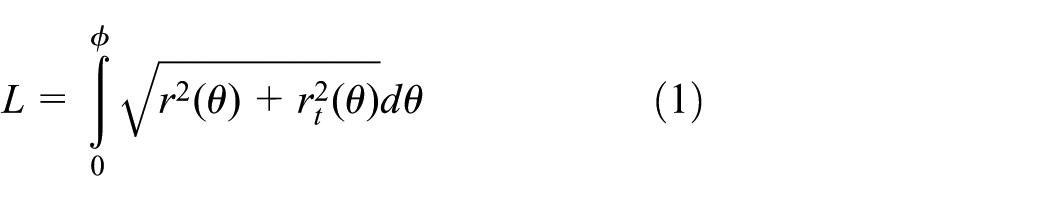
where
Define the arc length of the pitch curve of non-cylindrical gear in a single meshing cycle (i.e. from the trough to peak of pitch curve.) is
Equation of engagement angle
According to Lin et al., 2 the pitch curve of curve-face gear is cylindrical curve, so the addendum curve and root curve of the tooth are the equidistant curve of the pitch curve of curve-face gear. However, the cylindrical surface geometry problem is too complex, so it is better to expand the cylindrical pitch curve of curve-face gear into the plane curve.
Suppose a pair of teeth is meshing in Pi. As shown in Figure 2, coordinate XO1Y is rigidly connected to the meshing line N1iN2i. The origin point O1 is the center of the non-cylindrical gear. The Y-direction is the line connection of the centers of gear pair, and the X-direction is vertical with Y-direction. B1i is the actual enter meshing point and the B2i is the actual outer meshing point; N1i is the theoretical enter meshing point and the N2i is the theoretical outer meshing point; ai is the meshing angle as shown in Figure 2.

Change of normal load.
As shown in Figure 2,

According to the geometric theory, the coordinate values B1i (x1i, y1i) and B2i (x2i, y2i) are distributed on the meshing line. Furthermore, based on the meshing theory, B1i (x1i, y1i) is the intersection point between the root circle of curve-face gear and the meshing line and B2i (x2i, y2i) is the intersection point between the addendum circle of non-cylindrical gear and the meshing line, which can be represented as follows
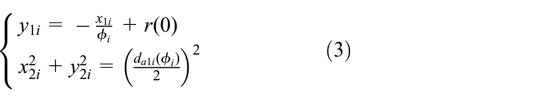
where
The coordinate values (x1i, y1i) and (x2i, y2i), which are, respectively, the value of B1i and B2i, can be obtained by equations (2) and (3).
Then, the limited rotating angle of each tooth profile is as follows

It is worth noting that for the curve-face gears, (1) the solution of
Equation of the undercut boundary line
Like the face gear, tooth width of the curve-face gear is also restricted by undercutting phenomenon. Therefore, it is important to study the undercutting of the curve-face gear.
Analysis of the undercutting phenomenon
The tooth surface of the curve-face gear is enveloped by the tooth surface of the involute spur gear and can be generated by the method of the shaper processing. The curve-face gear pair will be quite sensitive to the installation error if the gear shaper cutter is an identical copy of the non-cylindrical gear. In order to overcome the shortage, the contact traces of the non-circular gear and the curved-face gear should be limited in local region. 11 The local region can be achieved based on the following idea: the meshing of curve-face gear pair can be seen as the engagement of the imaginary cylindrical gear (gear shaper cutter) with the non-cylindrical gear as well as the curve-face gear, and the intersection of the instantaneous contact line L1 (caused by cylindrical gear and curve-face gear) and L2 (caused by cylindrical gear and non-circular gear) is the local region as shown in Figure 3(b).

Machining process of the curve-face gear: (a) feed trajectory of the curve-face gear and (b) local contact of curve-face gear pair.
In order to express the undercutting of curved-face gear clearly, we assume that the inner radius R1 of curve-face gear is small enough. Based on the API technology of SolidWorks, the simulative machining of curve-face gear can be obtained as shown in Figure 3(a).
Figure 4 shows the tooth profile after simulative processing, and it can be seen that the tooth profile

Undercutting of curve-face gear.
As a major factor affecting the under-cutting condition of curve-face gear, the pressure angle of the curve-face gear is not a constant. It changes periodically with the rotation angle
Equation of meshing
The coordinate systems are shown in Figure 5 in which Sk(xk, yk, zk), S1(x1, y1, z1), and S2(x2, y2, z2) are rigidly attached to the shape wheel, non-cylindrical gear, and curve-face gear, respectively, and SK(xK, yK, zK), SD(xD, yD, zD), and SF(xF, yF, zF) are rigidly attached to the corresponding frame. The rotation angle of the shape wheel

Basic parameters between tooth surfaces.
Therefore, the relationship between

where R is the radius of cylindrical surface; rg is the basic radius of shape wheel; and
Space location of the gear shaper cutter.
the tooth profile

where
The equation of tooth profile for the curve-face gear can be determined by the following coordinate transformation

where

where the meaning of basic parameters
Subsequently, the equation of meshing can be obtained as follows

where


where

Letting

Finally, substituting equations (11)–(15) into equation (10) yields the following

The two-bounded function of conjugate surface can be derived from differentiation of equation (10) as follows
where

Equation (17) then yields

where


Equation of the undercut boundary line
According to the theory of gearing, the undercut boundary line exits when both the equation of meshing and the one-bounded function of conjugate surface are equal to zero. 11
The value of one-bounded function G can be derived as follows

where

From equation (21), it can be seen that
Furthermore
which is then transformed to yield

The normal curvature

where

In equation (25), the arc length parameter of

where


Equation of pointing
Analysis of the pointing phenomenon
In outer diameter of face gear, the constant-height tooth may result in the intersection of the tooth surface as shown in Figure 7, and this is the pointing phenomenon of the face gear. For the curve-face gear, considering the complexity and the distribution of the tooth profile, the pointing phenomenon is followed by certain regularity.

Pointing of curve-face gear.
Equation of pointing
The tooth width of the curve-face gear, which affects the machining and carrying capacity of the curve-face gear, is limited by the tooth pointing. The maximum outer diameter of the curve-face gear can be got based on previous research results. 20
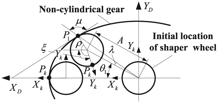
As shown in Figure 8(a), the rotation axes of shaper wheel and curve-face gear are OKZK and OFZF, respectively. OkI is the instantaneous axis between shaper wheel and curve-face gear. P is the pitch point and R is the cylindrical radius of pitch point P. Plane

Pointing condition of curve-face gear: (a) derivation of tooth pointing and (b) cross section by plane
The approximate solutions of pointing diameter R2 are based on the following ideas: (1) the tooth profile of curve-face gear is regarded as the straight line. Namely, the tooth profiles of curve-face gear on the cross section
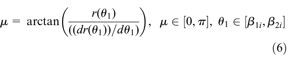
The pointing outer diameter R2 can be represented as

where rk is the pitch radius of shaper wheel and u can be calculated by equation (6),
The design parameter a can be determined as follows
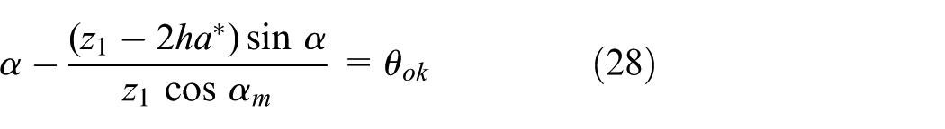
where

By equation (27), since
Calculation results and analysis
Through above theoretical analysis, the tooth width formula of curve-face gear is B = R2min − R1max. In the formula, R2min represented the minimum outer diameter which is non-pointing, and R1max represented the maximum inner diameter which is non-undercutting. Using the MATLAB calculation program, the variation of R2min and R1max can be calculated, which are affected by modulus m, tooth number z1, the order of non-cylindrical gear n1, the order of curve-faced gear n2, and eccentricity e of the non-cylindrical gear. Simultaneously, the variation of pointing and undercutting of tooth profile in a single meshing cycle is analyzed. According to the analysis, the tooth most easily undercutting and pointing is found, and the most reasonable inner and outer diameters can be determined. Furthermore, the tooth width can be obtained. This is the discriminant basis of tooth width of curve-face gear, which forms the design theory of curve-face gear, and the results are shown in Table 1. The basic parameters of curve-face gear pair are shown in Table 1.
Geometric parameters for the processing of the curve-face gear pair.

In order to obtain the undercutting inner diameter R1, substituting equation (19) and equations (21)–(26) and corresponding parameters
Figure 9 describes the changes of the inner diameter R1, which comes from the undercutting position of curve-face gear, and LH is the corresponding tooth height of every undercutting point. Take a single meshing cycle (from trough to peak of pitch curve) (

Variation of undercutting inner diameter R1: (a) the influence of the parameters of m and z and (b) the influence of the parameters of n1, n2, and e.
Figure 9 shows that no matter how the parameters change, the undercutting inner diameter R1 at trough position is always the maximum. Namely, the non-undercutting of curve-face gear can be maintained by ensuring that the undercutting phenomenon does not happen at the trough position. The study found that the trough position is most prone to interference due to the minimum pressure angle. Therefore, we can increase the pressure angle appropriately by expanding the center distance between gear pairs to reduce undercutting radius.
Based on equations (8)–(16), (19), and (20), for case m, 2, 3, and 4. z1, 18, 20, and 22; and n2, 2,4 and 6, respectively. The undercutting radius can be calculated as shown in Figure 9(a) and (b). These figures show that with the increasing basic parameters, undercutting radius tends to increase mainly due to the changes of the gear dimension. Fixing the other parameters gives eccentricity e of 0.1, 0.2, and 0.3, and the order of non-cylindrical gear n1 of 1, 2, and 4, respectively. It is clear that the undercutting radius reduces with e and n1 increase. it is mainly due to the increasing of e and n1, the wave range of pressure angle enlarges, which results in the minimum value of the pressure angle is smaller, and the maximum value is larger. 13 Therefore, it is more and more prone to interference.
Figure 10 gives the results of the outer diameter R2 in different parameters. It is clear that the pointing outer diameter R2 at trough position is the minimum, which is unaffected by parameters change. In equation (27), when

Variation of pointing outer diameter R2: (a) the influence of the parameters of m and z and (b) the influence of the parameters of n1, n2, and e.
Compare the results in Figure 9 with Figure 10, the change trends of the outer diameter R2 are the same with the increasing of m, z1, n1, and n2. But with the increase in the eccentricity e, the pointing radius is decreased. In equation (27),

Variation of R2min and R1max: (a) the influence of the parameters of m and z and (b) the influence of the parameters of n1, n2, and e.
Minimum tooth width B of curve-face gear.

From Table 2, the tooth width B increases with basic parameters m, z1, n1, n2, and e due to the rising of R2min and the reducing of R1max. Furthermore, the influence of z1 and n1 is minimal, and n2 is the largest. Therefore, in the long tooth width of limited gear size, the value of z1 and n1 can be appropriately increased.
Experiment of curve-face gear
The feasibility of the theoretical calculation is received by the experiment of curve-face gear. The gear the processing technology of curve-face gear is not yet mature, so the method of additive manufacturing (three-dimensional (3D) printing) is adopted. In this experiment, the curve-face gear of undercutting and pointing at the same time is processed. The basic parameters of curve-face gear pair are shown in Table 2.
Before the fabrication process, the molding chamber had to be preheated. When the fabrication began, the workbench moved to its original position. A layer of metal powder was paved on the workbench. Then, certain amount of inert gas was passed into the molding chamber. The processing would automatically start as soon as the oxygen content in the molding chamber was lower than a certain value. The metal powder was irradiated by computer controlled laser beams so that the shape of solidified metal can coincide with the layered geometric model of the component. Then, the workbench moved downward for a distance of one layer’s thickness. Another layer of metal powder will be paved and the above process would be repeated. Eventually, the required components could be obtained. Figure 12 shows the fabrication process.

Fabrication process: (a) additive manufacturing, (b) wire cutting, and (c) processing entity.
Processing entity will be measured in three coordinate measuring center, measuring principle as shown in Figure 13. These measured points are obtained by the P26-CNC (computer numerical control) gear measuring center from Klingelnberg. The main workflow is shown in Figure 14.

Detection process of curve-face gear.
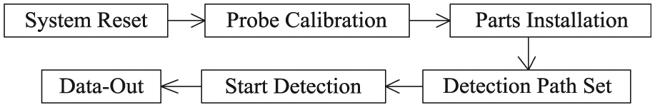
Detection workflow.
As shown in Figures 13 and 14, in order to obtain the coordinate value of pointing and undercutting points, the detection path can be determined by controlling the degree of freedom (DOF) of measuring center. By this way, the undercut boundary line and pointing point of each tooth profile can be easily detected. The undercutting inner diameter R1 and pointing outer diameter R2 of the tooth profile are obtained by measuring the entity, comparing with the theoretical data, and the results are shown in Figure 15.

Comparison of theoretical results and experimental results: (a) the comparison of R1, R2, and B and (b) the relative error of R1, R2, and B.
As shown in Figure 15(b), the maximum error of R1 is about 0.06 mm, and the relative error is less than 0.5%; the maximum error of R2 is about 0.25 mm, and the relative error is less than 1%. So the experimental test results are close to the theoretical calculation:
From the trough to the peak position of pitch curve, the rising of R2min and reducing R1max result in the rising of B. Therefore, the tooth at the trough position is most prone to pointing and undercutting. Namely, it is the discriminant basis of tooth width of curve-face gear.
The theoretical calculation of the maximum inner diameter R1max is 66.67 mm, the minimum outer diameter R2min is 84.24 mm, and the minimum tooth width Bmin is 17.57 mm, but the experiment results of
The relative error of minimum pointing diameter compared to maximum undercutting diameter is larger. The reason is that the pointing equation is derived based on the method of geometric approximate evaluation which leads to certain calculation errors.
Conclusion
In this article, the undercutting and pointing conditions of curve-face gear considering the tooth profile difference are analyzed based on the theory of boundary function and geometric approximate evaluation. The equations of the theoretic undercutting and pointing conditions are derived and simulated using mathematical software. The numerical results show that the undercutting inner diameter R1 decreases from the trough to the peak position of pitch curve, but the pointing outer diameter R2 and the minimum tooth width are the opposite. That is, the positions which most likely to occur undercutting and pointing are at the trough location of pitch curve. Therefore, tooth width at trough position can be used as the standard to determine the minimum tooth width.
To identify the feasibility of the theoretical calculation, the experiment of curve-face gear considering undercutting and pointing phenomenon is proposed. The results show that the analysis results are consistent with the actual processing phenomenon, which is helpful to the engineering application of the curve-face gear.
Footnotes
Academic Editor: Mark J Jackson
Declaration of conflicting interests
The author(s) declared no potential conflicts of interest with respect to the research, authorship, and/or publication of this article.
Funding
The author(s) disclosed receipt of the following financial support for the research, authorship, and/or publication of this article: The authors would like to appreciate their supports from the National Natural Science Foundation of China (51275537) and Graduate Student Research Innovation Project (CYB15019).