
Abstract
To improve the load-bearing capacity of non-circular gear, a design method with asymmetric pressure angles was constructed. The method for forming tooth profiles of non-circular gear based on a rack with asymmetric pressure angles was studied, the enveloping motion model of the profile-forming process and the mathematical model for extracting the profile-forming points were analyzed. The correctness of the profile design by using the motion simulation method and the enhancement of tooth root bending strength were verified. To analyze the undercutting phenomena for non-circular gear, a graphical method for identifying undercutting in each tooth profiles of non-circular gear was designed. Finally, a design case with asymmetric pressure angles was used in the high-pressure constant-flux pumps, and the results show that the bearing capacity of the gear pair was significantly improved, and the tooth fracture phenomenon was eliminated.
Keywords
Introduction
The non-circular gear plays a special role in mechanical transmission owing to its variable ratio. They are now widely used in advanced agricultural machines, 1 automobiles, 2 fluid pumps,3,4 and other equipment. However, due to the transmission characteristics of non-circular gear, there is a large dynamic load in the transmission process, and the machining and assembly errors are easy to cause tooth meshing impact, which limits the use of non-circular gear in heavy-duty situations.
When considering the transmission design of non-circular gear for practical applications, the bearing capacity is a key issue to be considered. When the non-circular gear transmits nonlinear heavy load motion, the non-circular driven gear rotates at variable speed. The direction of the rotating torque of the non-circular driven wheel changes frequently due to the action of meshing, which will produce a large dynamic load, which will cause a series of problems such as tooth deformation, gear pair stuck, meshing impact, and shortened life of gear pair. At present, the research on the load-bearing capacity improvement of non-circular gear pairs is lacking.
At present, generalized involute profile is widely used to design tooth profile of non-circular gear. Such a profile can be considered as the involute curve generated by the pure rolling of a straight line along the non-circular pitch curve. The numerical calculation methods for this tooth profile have been studied in Tan et al., 5 and Li et al. 6 and the direct generation methods for these profiles have been studied in Li et al. 7 and Han et al. 8 based on generating cutting method. Several studies have been conducted to enhance the load-bearing capacity of non-circular gear. The undercutting property of non-circular gear was investigated to improve tooth strength by avoiding undercutting. 9 In another study, the concept of high contact was used for the design of the tooth profiles of non-circular gear 10 to enhance their tooth strength. In addition, in order to improve the load bearing capacity of gear, many scholars have carried out a lot of research on improving the bending fatigue characteristics of gear teeth, and put forward some useful methods.11–13 In this paper, a non-circular gear pair with asymmetric pressure angles is designed to improve the load bearing capacity, and its undercutting phenomena are also analyzed.
Design of a non-circular gear with asymmetric pressure angles
Definition of asymmetric pressure angles
To machine a non-circular gear, the same cutters used for machining cylindrical gear can be used, including hob, rack, and gear cutters. According to the meshing principle, at an intersection point between the non-circular pitch curve and the tooth profile of a non-circular gear, the angle between the tangent to the pitch curve and the normal to the gear profile should be equal to the tooth profile angle or pressure angle of the cutter. For a non-circular gear, this angle is called as the pressure angle of the pitch curve of the non-circular gear. The pressure angles of a non-circular gear are defined as shown in Figure 1.
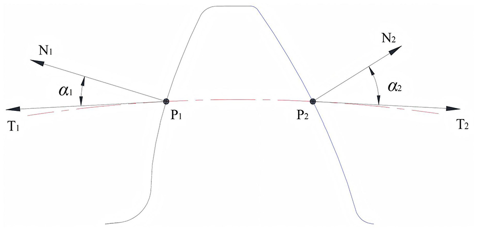
Pressure angles of left and right profiles of a non-circular gear.
As shown in Figure 1, the pitch curve of the non-circular gear intersects with the left and right tooth profiles of a gear tooth at points P1 and P2, respectively. At P1, the pressure angle is the angle α1 between the tangent T1 to the pitch curve and the normal N1 to the tooth profile at that point. Similarly, at point P2, the pressure angle is α2. When α1 = α2, the pressure angles of the left and right tooth profiles of each tooth of the non-circular gear are equal, so this non-circular gear is referred to herein as a non-circular gear with symmetric pressure angels. When α1 ≠ α2, the pressure angles of the left and right tooth profiles of each tooth of the non-circular gear are not equal, so this non-circular gear is referred to herein as a non-circular gear with asymmetric pressure angles.
Solving tooth profiles of a non-circular gear with asymmetric pressure angles
Enveloping motion model of a rack with asymmetric pressure angles
To solve the tooth profiles of a non-circular gear with asymmetric pressure angles, we used the generating cutting method, which involves creating a model for a rack with asymmetric pressure angles and rolling the rack center-line along the non-circular pitch curve. During this rolling process, a Boolean operation was performed on the gear blank and rack to generate the tooth profiles of the non-circular gear with asymmetric pressure angles. 14
As shown in Figure 2, the geometrical model of the rack with asymmetric pressure angles is illustrated in the coordinate system xoy. This rack is geometrically characterized by unequal pressure angles of its left and right tooth profiles. The basic tooth profile of the asymmetric rack consists of the tooth-tip arcs and straight lines on both sides. During the pure rolling of the rack center-line along the non-circular pitch curve, the straight-line profiles envelop the tooth profiles of the non-circular gear with asymmetric pressure angles, while the arcs on both sides envelope the root transition curves.

Schematic diagram of the rack with asymmetric pressure angles.
The tip radius is calculated by the following equation 8 :
where, αc and αd are profile pressure angles;
In Figure 2, points A, B, C, and D represent feature points in the rack drawing, and their coordinates can be calculated using the following equations:

According to the above equations, one tooth slot of the asymmetric rack can be drawn. Then, the tooth-profile points of the remaining teeth can be drawn by sequentially translating points A, B, C, and D by one tooth pitch. The geometric model of the asymmetric rack can be obtained by addendum rounding.
The process of machining a non-circular gear using a rack-shaped cutter can be understood kinematically as a pure rolling of the rack pitch line along the non-circular pitch curve. According to the meshing principle of conjugate profiles, the profile of a non-circular gear is the envelope curve generated by the family of straight lines during the motion of the straight-line profile of the rack. The process of enveloping the tooth profile of the non-circular gear with the rack tooth profile needs to be mathematically realized by the pure rolling of the rack center-line along the non-circular pitch curve. 15 The planar motions of the rack are shown in Figure 3.

Planar enveloping motions of the rack with asymmetric pressure angles.
As shown in Figure 3, in the coordinate system XOY, the polar origin of the pitch curve of the non-circular gear blank coincides with point O. The pitch line of rack T0 coincides with the X-axis. Point A is the starting point of the pure rolling of the rack pitch line with respect to the non-circular pitch curve, and point B is a point on the pitch curve where the rack pitch line has rolled to. At this point, the rack is denoted as T3. Rack T3 can be obtained through a series of planar motions of T0: first, Rack T0 is translated leftward by a distance of l to obtain rack T1; then, Rack T1 is rotated counterclockwise by Ψ around point O to obtain rack T2; finally, Rack T2 is translated from point O to point B to obtain Rack T3.
Given the polar coordinate equation of the pitch curve of the non-circular gear r = r(φ), the module of the gear m, the arc length from point A to point B on the pitch curve SAB, and the polar tangential angle at point B μ, the calculation equations for the parameters required for the planar motions of the rack are as follows:

By obtaining a series of discrete points on the non-circular pitch curve and calculating the envelope position of the rack at each discrete point, the envelope trajectory of the rack with respect to the non-circular gear can be obtained. Due to pairwise meshing in a non-circular gear pair, it is necessary to specify the distribution of tooth slots or teeth at specified positions on the pitch curve, which can be addressed by adjusting the addendum midpoint or slot midpoint of rack T0 to be located on the Y-axis.
Generation of profile-molding feature points
The theoretical profile of a non-circular gear should be the envelope curve generated by the family of straight lines of the rack tooth profile during its enveloping motion, as well as the extended involute curve generated by the tooth tip of the rack. However, given the substantial differences in tooth profiles among non-circular gear, solving the theoretical profile mathematically becomes exceedingly cumbersome and complicated. Starting directly from the family of envelope straight lines that generate the theoretical tooth profile and extracting the data points from it, which are close to the theoretical tooth profile, can make the tooth profile solving process for non-circular gear simple and efficient. The envelope trajectory of the rack with respect to the non-circular gear is shown in Figure 4.

Envelope trajectory of the asymmetric rack with respect to the non-circular gear.
As shown in Figure 4, the tooth profile of the non-circular gear can be enveloped by the motion trajectory of the rack tooth profile. With the help of the secondary development interface of 3D modeling software, the process of subtracting materials from the gear blank by the rack and generating feature points for forming the tooth profile can be completed. The resulting overall tooth profile is shown in Figure 5.
Enveloped overall tooth profile of the non-circular gear.
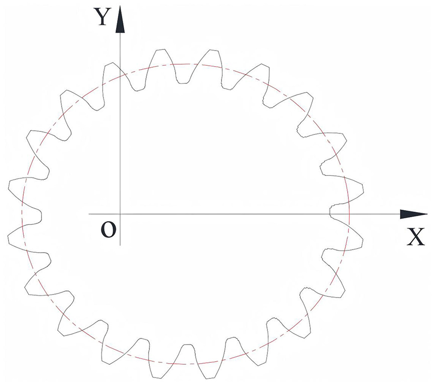
The process of generating the feature points of the tooth profile during the enveloping process is shown in Figure 6.

Process of generating the feature points of the tooth profile.
As shown in Figure 6 above, points P1–P10 are connected sequentially to form the basic outline of the theoretical tooth profile curve. These points are referred to as profile-forming feature points. Points P1–P6 form the meshing section of the tooth profile curve, and points P7–P10 form its dedendum section. We can understand the generation of these profile-forming feature points as follows: The rack and the tooth blank are considered as solid entities. Whenever the rack moves to a specific position, the tooth blank subtracts the rack, so that the tooth profile can be generated on the tooth blank after being cut by the rack, thereby generating the profile-forming feature points. In the tooth profile generated by the rack cutter on the tooth blank, in addition to the profile-forming feature points, there are some invalid data points, such as points Q1 and Q2 shown in the figure. It is necessary to extract valid profile-forming feature points from these points to generate each slot curve.
Extraction of tooth-profile data points
The gear profile shown in Figure 5 comprises the profile-forming feature points that form each slot curve. To facilitate software processing, the tooth profile generated by cutting the blank with the rack envelope is saved as a DXF file. The DXF file records data points that form all the graphical elements in a drawing, and it can be read and processed using a data processing software. To facilitate the subsequent generation of the tooth profile and analysis of individual teeth, the processing of the DXF file is divided into two steps: First, differentiate each tooth slot by numbering; second, extract valid profile-forming feature points in each slot.
As shown in Figure 6, among the profile-forming feature points P1–P10, P6 represents the end point of the meshing section, while P1 represents the intersection point of the rack tooth profile and the tooth tip curve. In this paper, P6 represents the demarcation point of the tooth profile, and P1 represents the top of the tooth profile. The sequentially connected points P1–P6 forming polyline do not affect the tooth profile. The theoretical tooth profile curve is tangent to line segments P1P2, P2P3, P3P4, P4P5, and P5P6 simultaneously. Points P7, P8, P9, and P10 are valid points on the root transition curve. Points Q1 and Q2 are intermediate points generated during the envelope cutting process, which should be excluded to generate the root curve.
For ease of description, points similar to Q1 and Q2 are referred to as root-forming intermediate points. When observing a tooth slot from the inside of the gear, the profile on the left side is referred to as the left profile that on the right side is referred to as the right profile. Partial enlarged details of the graphical elements constituting the tooth slot are shown in Figure 7.

Partial enlarged details of the graphic elements of the tooth slot.
Points B and D are valid profile-forming feature points, while points C and D are root-forming intermediate points along the search direction of the profile-forming feature points as for the left profile. To effectively extract the profile-forming feature points along the search direction, we can use a method based on the clockwise direction of the triangle formed by three adjacent points. The method is illustrated here by considering point B and discarding point C. In the case of ΔABC, the direction from points A to B to C represents counterclockwise, while in the case of ΔBCD, the direction from points B to C to D represents clockwise. Suppose the coordinates of three adjacent points along the search direction are (x1, y1), (x2, y2), and (x3, y3). The equation for identifying the direction formed by connecting three adjacent points in sequence is as follows:

In equation (4),
By reading the data from the DXF file and differentiating the teeth and extracting valid profile-forming feature points, we can generate the profiles of the teeth of non-circular gear as shown in Figure 8.
Tooth profile consisting of extracted profile-forming feature points.
As shown in Figure 8, the profiles of slots formed by extracted valid profile-forming feature points approximate the theoretical slot curve. If the approximation error between these profile-forming points and the theoretical tooth profile is small enough, these points can be used to generate the theoretical slot curve through curve interpolation. Among these profile-forming feature points, those between the demarcation points of left and right profiles are the actual positions of the top of the rack-cutter profile. There is no approximation error between these points and the theoretical root curve. The polyline formed by sequentially connected data points between the demarcation point of the left/right profile and the top of the left/right tooth slot is a tangential outer polygon of the theoretical profile curve of the left/right meshing section. There exist varying approximation errors between these points and the theoretical tooth profile curve, which should be quantitatively analyzed.
Design example of an elliptical gear with asymmetric pressure angles
Based on the principle of the generating cutting motion of the centerline of the asymmetric rack along the non-circular pitch curve previously derived, as well as the secondary development of the 3D software SolidWorks, we can create a solid model of a non-circular gear with asymmetric pressure angles. We can create solid models of the asymmetric rack and the non-circular gear blank, respectively, and then allow the rack centerline to move along the non-circular pitch curve. At each discrete point on the pitch curve, a Boolean subtraction operation is performed on the gear blank and the rack to cut the gear blank. The data at discrete points of the tooth profile generated during the gear blank cutting process is collected, and spline curve fitting is performed on these points to generate a smooth tooth profile curve.
Take an elliptical gear with asymmetric pressure angles as a design example. The relevant parameters are as follows: Number of teeth z = 19; module m = 4; eccentricity k = 0.4; tooth width B = 10 mm. With the pressure angle on the non-working-side αc = 20° and the pressure angle on the working side αd = 30°, the solid model of the elliptical gear with asymmetric pressure angles is shown in Figure 9(a); with the pressure angles on both sides being 20°, the solid model is shown in Figure 9(b).

Solid models of elliptic gear with asymmetric and symmetric pressure angles: (a) with asymmetric pressure angles and (b) with symmetric pressure angles.
To verify the correctness of the design of the non-circular gear pair with asymmetric pressure angles, a kinematic simulation analysis of the designed elliptical gear pair with asymmetric pressure angles was conducted to check its tooth profile interference and gear ratio. The digital simulation model of the elliptical gear pair with asymmetric pressure angles is shown in Figure 10.

Motion simulation model of the elliptic gear pair with asymmetric pressure angles.
Results of the motion simulation showed that the designed elliptic gear pair with asymmetric pressure angles operates smoothly without profile interference. To verify the superiority of a non-circular gear pair with asymmetric pressure angles over a non-circular gear pair with symmetric pressure angles in terms of mechanical properties, we took the previously created elliptical gear with asymmetric pressure angles and elliptical gear with asymmetric pressure angle as examples, and used the finite element method to analyze the stress at their tooth roots.
16
The mechanical parameters of the two gear pairs are as follows: Modulus of elasticity E = 2.1 × 10¹¹ Pa, Poisson’s ratio

Comparative analysis of stress nephograms of tooth 2: (a) with asymmetric pressure angles and (b) with symmetric pressure angles.
Figure 11 shows the stress nephograms of the tooth on the two elliptical gears, the mesh division accuracy of the two gears is the same, and the number of mesh cells in Figure 11(a) and (b) is 13,820 and 13,808 respectively. Under the same load conditions, the stress at the root of the tooth on the elliptical gear with one pressure angle is around 500 MPa, while the stress at the root of the tooth on the elliptical gear with asymmetric pressure angles is 360 MPa. Gear tooth 1–19 on the elliptical gear with asymmetric pressure angles and that with one pressure angle were analyzed under the same load conditions. The tooth root bending stress results are shown in Figure 12.

Comparison of tooth bending stresses.
As shown in Figure 12, the tooth root bending strength of the elliptical gear with asymmetric pressure angles is substantially higher than that of the elliptical gear with symmetric pressure angles, indicating a higher load-bearing capacity.
Identification of undercutting of a non-circular gear with asymmetric pressure angles
Undercutting is a crucial issue that needs careful consideration in the design and manufacturing of non-circular gear. Undercutting may reduce the contact ratio and tooth root bending strength of a gear pair. Identifying undercutting of a non-circular gear is much more complicated than identifying undercutting of a cylindrical gear. The radii of curvature of the teeth on a non-circular gear differ from one another, and the radius of curvature of the same tooth also varies, making it highly complicated to assess undercutting of a non-circular gear. 17 In Wu and Wang, 18 a method was studied for identifying whether the hobbing process results in undercutting by using the equivalent tooth-profile method. This method solves the radius of curvature at each point on the non-circular pitch curve, and obtains the following equation based on the undercutting identification principles for cylindrical gear.

Where, mmax refers to the maximum allowed module of the non-circular gear without undercutting, ha refers to the addendum coefficient, α refers to the pressure angle, and ρmin refers to the minimum radius of curvature of the non-circular pitch curve.
The mechanism of undercutting can be understood from the following two perspectives: From the perspective of machining, the tool is used to cut away the previously enveloped pressure tooth profile as it progresses. From the perspective of geometric characteristics of the tooth profile curve, there are cusps on the pressure section of the tooth profile curve, which make the transition points between the pressure profile and the tooth root no longer smooth. Based on the understanding of the geometric characteristics of undercutting and the basic principle of tooth profiles of a non-circular gear enveloped by using the graphical method, we proposed a method to identify whether and to what degree undercutting occurs in each tooth profile. Partial enlarged details of the tooth profiles generated by using the envelope method near the demarcation points of the pressure tooth profile and tooth root curve are shown in Figure 13.

Partial enlarged details near the demarcation point of the tooth profile: (a) without undercutting and (b) with undercutting.
As shown in Figure 13(a), all the points marked in the figure are profile-forming feature points. Among these points, Point D is the demarcation point of the tooth profile and Point E is the first root-forming point. The meshing tooth profile enveloped by the polyline ABCD can pass Point E smoothly. Let the angle between line segments BC and CD be
As shown in Figure 13(b), points A, B, E, and F are profile-forming feature points, among which Point E is the demarcation point of the tooth profile. Point C is a profile-forming feature point formed by the envelopes BC and CD. However, due to the appearance of envelope EF, Point C is replaced by Point E, indicating that the envelope EF cuts away the meshing tooth profile formed by envelope ABCD, thereby resulting in undercutting. Let the angle between line segments AB and BC be
The comparison in the above figure indicates that the method for identifying whether undercutting occurs in the tooth profile can be defined as follows: By analyzing the ratio of angles between adjacent line segments near the demarcation point of the tooth profile, we can confirm whether undercutting has occurred by defining
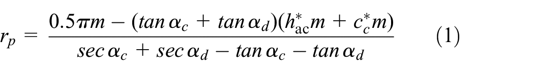
The result of the Boolean operation for the tooth profile of the non-circular gear with asymmetric pressure angles is shown in Figure 14.

Tooth profile of the non-circular gear with asymmetric pressure angles based on Boolean operation.
The elliptical gear has a tooth slot at the zero pole angle, which is designated as Slot 1. The tooth slot number K increases in the counterclockwise direction. By definition, K-0.5 corresponds to the right tooth profile of the tooth slot, and K corresponds to the left tooth profile of the tooth slot. According to the undercutting identification method described above, the undercutting degrees of these tooth profiles are shown in Figure 15.

Undercutting degrees of the tooth profiles of the elliptical gear.
The undercutting degrees of the right tooth profiles of slots 3 and 4, as well as the left and right tooth profiles of slots 5 and 6 in this non-circular gear are ∼1, indicating that no undercutting occurred. Undercutting of various degrees occurred in all other tooth profiles, with the undercutting degrees of the right tooth profiles of slots 9 and 10 being the most severe.
As can be seen from equation (5), for the elliptic gear with asymmetric pressure angles, the minimum curvature radius condition of the pitch curve without undercutting is 34.19 mm for the 20° tooth profiles, and 16 mm for the 30° tooth profiles. Combined with the curvature characteristics of the pitch curve, it can be seen that the tooth surfaces where undercutting occurs are numbered 1, 10, and 17 for the tooth profile with 20° pressure angle, and no undercutting will occur for the tooth profile with 30° pressure angle, which differs substantially from those obtained using the method proposed above. The main reason for such difference lies in the complicated tooth profiles of a non-circular gear. The position relationship between the cutter and the tooth profile during the hobbing process is complicated, making the equivalent tooth-profile method for identifying undercutting no longer applicable to non-circular gear. The undercutting judgment method of non-circular gear with asymmetric pressure angles proposed in this paper can be summarized as the following flowchart (Figure 16).

The undercutting judgment flowchart of non-circular gear.
The distribution of gear teeth can also affect the analysis results for the undercutting identification of non-circular gear. This is because differences in gear tooth distribution lead to variations in tooth profile used along the pitch curve, which would have different impacts on the root transition section. In the case of a helical non-circular gear, in addition to considering the impacts of the differences in tooth distribution, it is also necessary to consider the differences in tooth profile in different cross-sections along the tooth width direction caused by helical teeth. These differences can result in different analysis results for the same tooth slot in different cross-sections.
Case study on non-circular gear with asymmetric pressure angles
Non-circular gear are extensively applied in the industries of fluid pumps and motors, for example, low-speed high-torque motors, rotor pumps, and constant-flux pumps. 19 An industrial high-pressure constant-flux pump is driven by a non-circular gear pair. This design has experienced frequent tooth fractures in practical uses. The images of the damaged gear teeth are shown in Figure 17.

Fractured teeth of a non-circular gear with symmetric pressure angle.
To enhance the strength of the gear teeth of this non-circular gear pair, the design was improved by using a non-circular gear pair with asymmetric pressure angles proposed in this paper, and the undercutting degrees of the roots of the teeth were tuned and controlled by using the undercutting identification method proposed in the paper. The finally improved design by using a non-circular gear pair with asymmetric pressure angles, namely 26° on the working side and 20° on the non-working side, is shown in Figure 18.

Improved design using a non-circular gear pair with asymmetric pressure angles.
The non-circular gear pair with asymmetric pressure angles was successfully machined by using a slow-feeding wire cut machine, and can operate smoothly. This validates the correctness of the tooth profile solving method proposed in this paper. The improved design with asymmetric pressure angles has shown outstanding tooth load-bearing capability in practical use. No tooth fractures have ever occurred over the past year of operation. The physical assembly of the improved design is shown in Figure 19.

Physical assembly of the improved design.
Conclusions
(1) A design method of non-circular gear with asymmetric pressure angles is proposed. The feature points of the gear profile are obtained based on the enveloping motion of the rack with asymmetric pressure angles.
(2) The feasibility of non-circular gear transmission with asymmetric pressure angles is verified by kinematic and mechanical simulation, and the advantage of non-circular gear with asymmetric pressure angles in load bearing is also verified by finite element method.
(3) A graphical method for determining the undercutting phenomenon of non-circular gear with asymmetric pressure angles is proposed, which can effectively evaluate the undercutting of each tooth profile and calculate the undercutting degree, and can be used for the design optimization of non-circular gear.
Footnotes
Handling Editor: Sharmili Pandian
Author contributions
DL was in charge of the whole trial and wrote the manuscript; LW assisted with design and experiment analyses. All authors read and approved the final manuscript.
Declaration of conflicting interests
The author(s) declared no potential conflicts of interest with respect to the research, authorship, and/or publication of this article.
Funding
The author(s) disclosed receipt of the following financial support for the research, authorship, and/or publication of this article: This work was financially supported by the National Natural Science Foundation of China (Grant No. 52075142).
Availability of data and materials
All data generated or analyzed during this study are included in this published article.