
Abstract
In order to study the coupling effect of the equipment and the launching site during the erecting process of the vehicle missile system, the lumped parameter model of the multi-stage hydraulic cylinder is deduced, the flexible multi-body dynamic model is established in ADAMS, and the normal and tangential coupling forces in the coupling relationship are derived. The coupling calculation model of the weapon system and the launching site is established in the co-simulation of the ADAMS and MATLAB/Simulink. The results show that the vertical slip of the launching platform is much greater than longitudinal and lateral ones. The erection angles of the cylinders at all levels when they begin to extend are 0°, 22.16°, 43°, and 65.52°, respectively, of which the speeds are 50 mm/s or so, and there are little limit impacts between the cylinders. The thickness of the surface layer has greatest influence on the stability and security of the launching platform, followed by the thickness of the base layer as well as the elastic moduli of the surface layer and the base layer. The conclusion provides important theoretical basis for the selection of the unsupported launching site.
Keywords
Introduction
The erecting of a missile is important to the weapon’s launching, while it also takes a lot of time to be finished. For the reason that the capability of satellite detecting and precise attacking continuously enhances these days, the missile weapon system is under great threat. Currently, domestic researches mainly focus on improving the speed and the smoothness of the erecting, and the dynamic models are simplified into a single-degree-of-freedom model consisting of only the erecting load and the cylinders, without considering the elastic deformation of the launching platform and the ground. As a result, the erecting missile cannot be studied as an integral process.
Aiming at large erecting systems, XX Huang et al. 1 established the dynamic and constraint equations of the erection system using the R-W method in multi-body system dynamics and built up the characteristic equation of the hydraulic system with the lumped parameter method. Based on the theory of multi-body system dynamics, QH Gao and colleagues2,3 established the dynamic model of the erection system using the software ADAMS through defining the designing variables, the state variables, and the state equations. WX He et al. 4 established the simulation model of the hydraulic system of which two cylinders are erected synchronously through the multi-body system computation software ADAMS and the hydraulic system simulation software Easy and analyzed the performance of synchronous erection. Using the software environment of ADAMS, AMEsim, and MATLAB/Simulink, XX Huang et al. 5 proposed the multi-software cooperative modeling and weapon system simulation method of the large-scale installations, which is subsequently adopted by many scholars. Considering the missile erection system as a flexible multi-body system, XG Yao et al. 6 built up the rigid-flexible coupling dynamic model using the software ADAMS and ANSYS and analyzed the mechanical characteristics during the erecting process of the flexible bodies.
This article outlined the vehicle-mounted missile system and its erecting process. First, considering the friction and impact forces of the cylinder, the lumped parameter model of the multi-stage hydraulic cylinder was derived. Second, considering the effects of the flexibility of the chassis and the wind load, a flexible multi-body dynamics model was established in ADAMS. Third, the coupling relation between the weapon system and the ground was divided into the coordination of displacement and mechanics, and then the expressions of the normal and tangential coupling forces were deduced. Based on above analysis, ADAMS and MATLAB/Simulink were used to establish the coupled calculation model of the weapon system and the ground. Finally, the erecting of vehicle-mounted missile weapon system was simulated to analyze the relationship between the structural parameters of the ground and the erecting.
Components of vehicle-mounted missile system
Vehicle-mounted missile is a complex system, including mechanical system, hydraulic system, and electrical system. According to the function, vehicle-mounted missiles can be divided into launching vehicles, erecting equipment, launchers, missiles, and other parts. Figure 1 is the schematic view of the composition of a vehicle-mounted missile weapon.

Composition of a vehicle-mounted missile weapon.
The erecting process of the vehicle-mounted missile weapon can be simplified as shown in Figure 2.
Topological image of a vehicle-mounted erecting missile weapon.
Model of the multi-stage hydraulic cylinder
Due to its compact structure, long stroke, and high thrust, the multi-stage hydraulic cylinder is capable of driving large payload to move from the horizontal position to the vertical position, which is thus extensively applied in missiles and their allied equipment. Because of the collision in the stretch-out process and the changing in effective action area, a multi-stage cylinder will produce too much impact during the erecting. 1 In order to complete the missile erecting movement within the prescribed time and ensure the smoothness and stability, an accurate dynamic model of multi-stage hydraulic cylinder system is needed. Figure 3 is the structure of a four-stage hydraulic cylinder.
Structure of a four-stage hydraulic cylinder.
During the erecting of a missile, the multi-stage oil cylinder is mainly influenced by the loading force, the hydraulic force, the friction, and the collision forces between the cylinder pistons. A multi-stage hydraulic cylinder mechanics model needs to be established after all the forces are analyzed.
Frictional force
The classical friction model believes that there are two forms of frictional force in the hydraulic cylinder. One is caused by the contact between piston and cylinder wall, including the static friction force and the Coulomb friction force, and the other one is viscous friction caused by the viscous liquid itself. These friction forces are all related to the relative speed. Figure 4 shows the curve of the friction coefficient changing with the speed.

Curve of the friction coefficient.
Many scholars have put forward hydraulic cylinder friction models. Wherein, the LuGre model proposed by C Canudas 7 involves the static friction, Coulomb friction, viscous friction, and the Stribeck effect (the effect that during the low relative speed, the friction decreases with the increase in relative velocity). This widely used model reflects the mechanism of friction movement, which is expressed as follows

where σ0 is the deformation stiffness coefficient; σ1 is the viscous damping coefficient; σ2 is the viscous friction coefficient; v is the relatively movement speed; vs is the boundary lubrication friction coefficient (the Stribeck speed); fc is the Coulomb friction force; fs is the maximum static friction force; and f is the total friction force.
This article selects the LuGre model for the friction calculation of erecting multi-stage oil cylinder. The relative coefficients are referred to in the literatures:8,9
Deformation stiffness coefficient is 2.1 × 10⁷;
Viscous friction coefficient is 0.1;
The max static friction force is 800 N;
Viscous damping coefficient is 150;
The Stribeck speed is 0.035 m/s;
Coulomb friction is 400 N.
Collision force
Every stage of hydraulic cylinder in multi-stage hydraulic cylinder is stopped by the collisions, which is the reason why the collision of the piston rod at all levels must be considered when the erecting dynamic characteristics of missile weapon are analyzed. The material of hydraulic cylinder can be regarded as steel. According to ADAMS, the contact parameters are chosen as follows:
Contact stiffness is 3.8 × 10⁴ N/mm;
Force function index is 1.5;
Static friction coefficient is 0.12;
Static friction converting speed is 0.1 mm/s;
Damping coefficient is 50 N s/mm;
Maximum penetration depth is 0.1 mm;
Friction coefficient is 0.1;
Friction converting speed is 10 mm/s.
Multi-stage oil cylinder lumped parameter model
A lumped parameter model of the hydraulic system can be established with the help of the bulk-cavity-node method. 1 Both rod end and non-rod chambers can be seen as a node cavity. According to the structure of the multi-stage hydraulic cylinder and the analysis of the friction and collision forces, two chamber pressure equations can be set up. Then the output forces at all levels can be calculated, thus obtaining the numerical model of multi-stage hydraulic cylinder system. Using four-stage hydraulic erecting as an example, the output force expression is shown as follows

where
Flexible multi-body dynamics model on the vehicular missile weapon system
Flexible body model
The mode synthesis method is applied to the analysis of large-scale multi-body systems with small deformation. The flexible structure is equivalent to a set of finite element model nodes; the deformation of the flexible body is a linear modal superposition system. While the missile is erecting, the chassis of the launch vehicle may undergo great deformation, especially at the beginning. Deformation of the chassis is much larger than other components, and the deformation of the chassis affects the loading of the front and rear leveling jacks to the ground. So it is necessary to establish a flexible body model for the chassis. In this article, the modal reduction method was adopted, and the finite element software ABAQUS was used to generate a flexible model of the chassis. After the modal analysis on the chassis was carried out, the first 30 truncated modes are selected. The first six modes represent rigid translation and rigid rotation. Table 1 lists the frequencies of the remaining 24 modes, which begin from mode 7. Figures 5–8 show four kinds of typical vibration modes other than rigid modes.
The 24 modes modal frequency (begin from mode 7).
Seventh mode of the chassis.
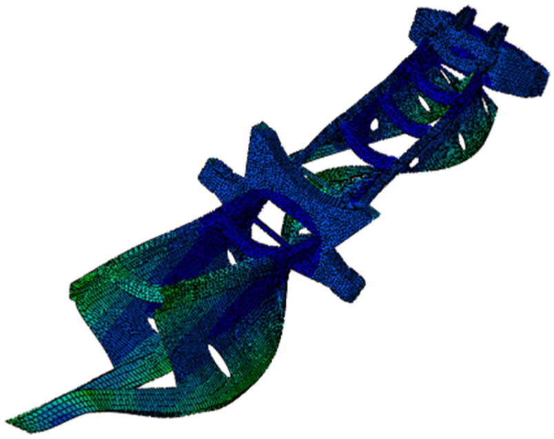
Ninth mode of the chassis.

The 12th mode of the chassis.

The 15th mode of the chassis.
Erecting wind load
According to the literature, 10 the impact of wind load during the erecting should not be neglected. Due to the randomness of the wind load, it is difficult to describe the wind load characteristics completely. This study ignored the random disturbance of wind load, considered the worst situation and assumed that the tube is always affected by wind pressure during the erecting, which are shown in Figure 9.

Wind pressure during the erecting.
There are many domestic and foreign researches about the wind model. In the engineering field, it is generally thought that wind speed can be decomposed into average wind speed and pulsating wind speed. The change of average wind speed along with the height is called the wind profile, and logarithmic wind profile and index of the wind profile table are commonly used. Logarithmic wind profile model was chosen in this article. 11 The formula is as follows

where V is the average wind speed at the height h; Vr is the average wind speed at reference height; hr is the reference height and it usually takes 10 m. For launch positions, α is 0.16.
The formula can be arranged as follows
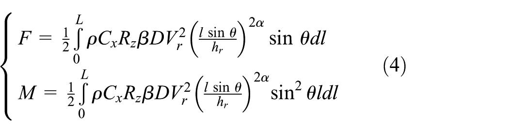
where D and L are, respectively, the diameter and length for the launch tube. And θ is the erecting angle. P is the wind pressure, which determines by the wind speed, the structure shape, and the height. In the formula, Cx is the aerodynamic drag coefficient, Rz is the wind pressure coefficient which increases with the height, β is the correction coefficient considering the wind, q is the dynamic head, ρ is the air density, 1.51 kg/m, and v is the average wind speed.
According to the related literature: 12
Air density is 31.51 kg/m3;
Air pressure increases coefficient of height is 0.7;
Dynamic coefficient for wind is 1.22;
Average reference wind speed is 5 m/s (grade 3 breeze);
Aerodynamic drag coefficient of launch tube is 1.3.
To be comprehensive, a flexible multi-body dynamics model for vehicle-mounted missile weapon system was established in the ADAMS software, which is shown in Figure 10.

Dynamic erecting model for vehicle-mounted missile weapon system.
Coupling between the weapon system and the ground
Two ways are usually used to consider the coupling effect between the weapon system and the ground. One is creating a unified controlling equation set and then solving them at the same time, and the other is establishing two equations of two systems, linking them via coupling relationship, and finally using an iterative method to calculate the system response. In this article, the ADAMS is used to perform the dynamics simulation of the missile weapon system, so using the first method to unify the ground control equation and the multi-body system control equation is difficult to realize. Therefore, the second iterative method was chosen.
Displacement coordination
As mentioned above, the weapon system which is supported by a leveling jack is always subject to the displacement constraints of the ground. This means the ground will deform itself to satisfy the displacement of the supporters without separation between the jack and the ground. Because the rigidity of the supporters under the jack is much larger than the ground, the deformation of the supporters will be so small that they can be considered as rigid bodies. The contact status is shown in Figure 11.
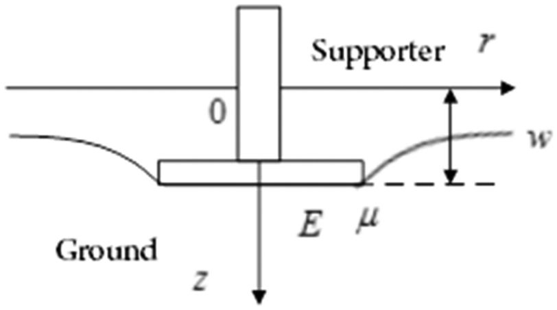
Contact status between the supporter and the ground.
The relation of displacement coordination can be expressed as follows

where wf is the displacement of supporters, and ws is the subsidence of the ground surface.
Mechanical coupling
The interaction force between the supporters and the ground is the contact force. The jack and the ground are affected by a pair of forces with equal magnitudes and opposite directions at the contact interface. In the process of erecting or launching a missile, the continuous variation of the center of gravity of the launching vehicle and the random wind load give the vehicle a tendency of lateral movement or even a lateral slip, which results in the existence of both normal contact force and tangential contact force at the same time.
Normal contact force
Richart and Whitman 13 use an approximate equivalent system to approach the elastic half space model and obtains the erecting vibration damping coefficient of the rigid circular object. In this article, the damping coefficient can be considered as follows

where µ is the Poisson’s ratio, G is the shear modulus of the ground, and ρ is the density of the ground.
Therefore, the normal contact force between the supporters and the ground can be written as follows

where Kv is the equivalent stiffness of the normal movement of the ground.
Tangential contact force
The transmitting device has two states in tangential direction: one is relative static (including relative motion trend), and the other is relative motion. So the coupling force should be calculated according to these two states. The calculation of tangential contact force is integrated as follows

where Qhm is the sliding friction force, Qv is the normal contact pressure, η is the sliding friction coefficient, Kh is the average tangential stiffness at the static state, and u is the tangential displacement.
Coupling calculation of weapon system and the ground
In view of the fact that the multi-stage hydraulic cylinder model, the weapon system of the flexible multi-body dynamics model, and the vibration coupling relationship between the weapon system and the ground have already been clear, MATLAB/Simulink and ADAMS are used to establish the coupling model of weapon system and the ground.
In this article, the whole model was divided into four parts: the flexible body dynamics model of the weapon system, the wind load model, the multi-stage hydraulic cylinder model, and the ground model. In the process of missile erecting, the hydraulic cylinder’s displacement and velocity, the supporters’ displacement and velocity, and the erecting angle of the missile will be, respectively, transmitted to the multi-stage hydraulic cylinder model, the ground model, and the wind load model with the help of the dynamics model. Then, the hydraulic driving force, the ground contacting force, and the wind load will feed back to the erecting dynamic model. The connection of all systems is shown in Figure 12.

Connection of all systems.
With Simulink, the modeling of the system can be accomplished by the combination of basic sub-modules, or by S function in MATLAB. 14 The calculation of the contact force of the ground and the random wind load contains the complex integral, which makes the S function be the only choice. The multi-stage hydraulic cylinder model is built using sub-modules, and the coupling calculation model is shown in Figure 13.

Coupling calculation model of the weapon and the ground.
Influence of parameters of the ground on erecting process
The key of missile launching without relying is choosing the ground reasonably. Therefore, it is necessary to study the ground parameters’ influences on the erecting process. Take a cement concrete road as an example, and the basic parameters are set as Table 2.
Basic structural parameters of the ground.

PCC: plain cement concrete.
If the erecting costs 100 s, and the missile is erecting at a uniform speed, then

Dynamic analysis of erecting process
In this section, the erecting process of the missile is simulated. Then, the parameters’ changing pattern of the normal and tangential contact force, and the displacement and the velocity of the cylinder of all supporters are analyzed. The results are shown in Figures 14–21.

Normal contact force.

Subsidence of the supporter.
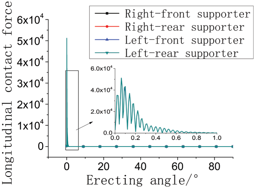
Longitudinal contact force.
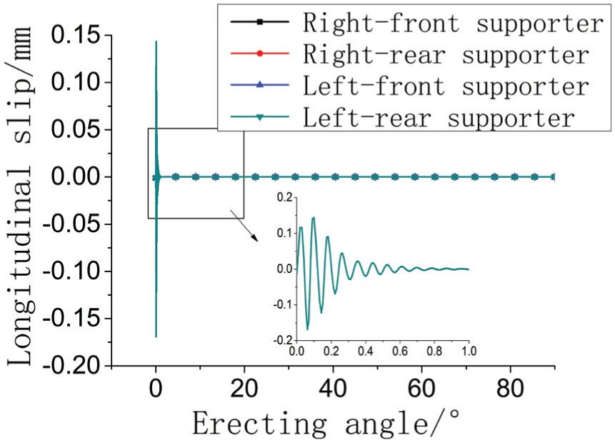
Longitudinal displacement.

Lateral contact force.
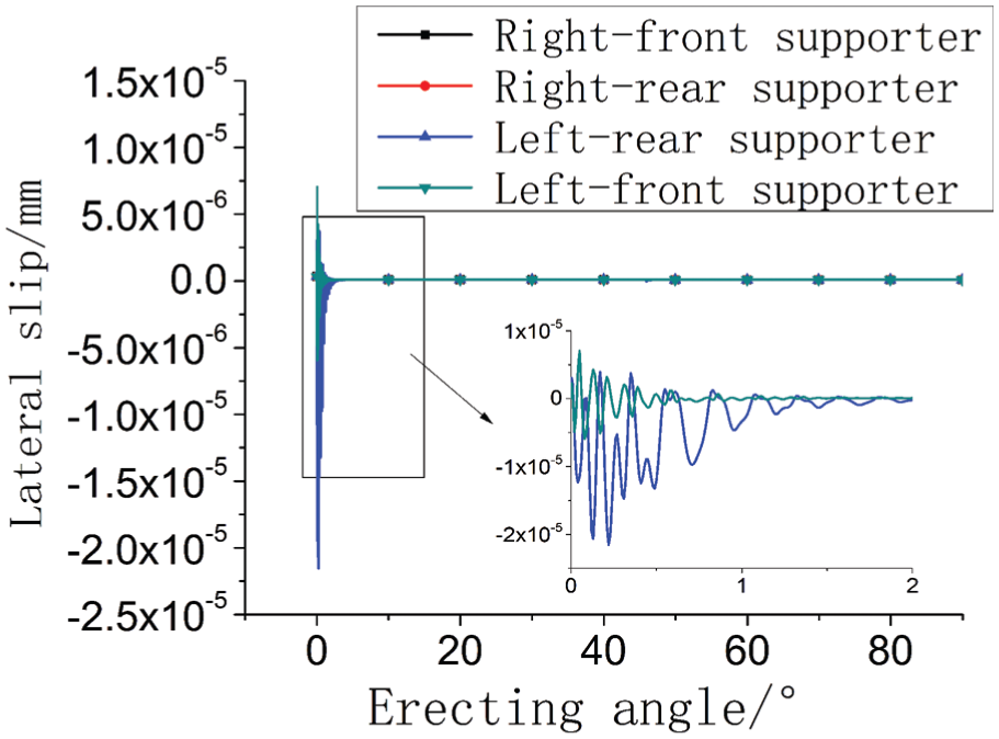
Lateral slip.

Displacement of hydraulic cylinders.

Velocity of hydraulic cylinders.
Analysis of the influence of the surface course to the erecting
There are two parameters that affect the mechanical properties of the surface course of the ground: the thickness of the surface course and its elastic modulus. In order to analyze the influence of the surface course on the erecting process, now assume that the thickness of the surface course is 20, 10, 15, and 5 cm, and the elastic modulus is 10,000, 20,000, 30,000, and 40,000 MPa. Other parameters are considered the same as Table 2. According to the analysis in the last section, the normal movement and the longitudinal movement of the launching platform are more dominant than its lateral movement, which makes the first two movements be the main physical variables of the coupling effect of the erecting process and the focus of this section. To facilitate the description of the results, different thickness in calculation are denoted as the thickness of 1, 2, 3, and 4 from thin to thick, and so are the elastic modulus as 1, 2, 3, and 4. The results are shown in Figures 22 and 23.

Subsidence of the front supporter in different thickness.

Subsidence of the rear supporter in different thickness.
According to this, the amount of the sinking of the supporters and the thickness of the surface course is approximately proportional (Figures 24 and 25).

Subsidence of the front supporter in different elastic modulus.
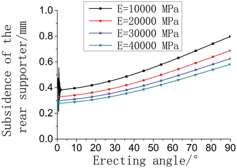
Subsidence of the rear supporter in different elastic modulus.
From above, it was found that the amount of the sinking of the supporters was negatively correlated with the elastic modulus of the surface layer, but no obvious proportional relationship was found. Comparing the ratio of the sinking on different thickness and elastic modulus, the sinking of launching platform and the supporting stiffness are more sensitive to the thickness of surface course. Therefore, the thickness of the surface course will make more effects on the stability and safety of the launching platform.
Analysis of the influence of the base course to the erecting
The influence of the base course of the ground to the erecting is analyzed in this section. Similar to section “Analysis of the influence of the surface course to the erecting,” we assume that the thickness of the base course (cement stabilized gravel) are, respectively, 10, 20, 30, and 40 cm. Elastic modulus are, respectively, 2000, 3000, 4000, and 5000 MPa. Results are shown in Figures 26 and 27.

Subsidence of the front supporter in different thickness.

Subsidence of the rear supporter in different thickness.
From above, the subsidence of front and rear supporters has negative correlation with the thickness of base course. But there is no significant proportion relationship (Figures 28 and 29).

Subsidence of the front supporter in different elastic modulus.
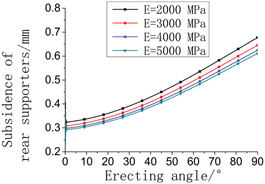
Subsidence of the rear supporter in different elastic modulus.
From above, it can be seen that the subsidence of front and rear legs has no obvious proportion relationship with the elastic modulus of the base course. Based on the above analysis, the sensitivity of ground parameters to the erecting is obtained. Based on thickness 1 and modulus 1, the ratio of thickness and the increase in elastic modulus is the abscissa, and the ratio of subsidence decrease is the ordinate. The result is shown in Figure 30.

Variation of subsidence with the thickness and elastic modulus.
From Figure 30, it can see clearly that among all the structure parameters of the ground, the thickness of each layer has bigger influence on the subsidence of supporting leg than elastic modulus. The order of the influence is as follows: the thickness of surface course, the thickness of base course, the elastic modulus of surface course, and the elastic modulus of base course. At the same time, the thickness of the surface course and the subsidence of the ground have the approximately linear relationship.
Conclusion
In this article, vehicle-mounted missile weapon system was used as the research object to perform dynamic simulation on the missile’s erecting and analyze the influence of the thickness, the elastic modulus of the surface, and the base course of the ground on the erecting. The coupling effect between weapon system and the ground during the erecting was also discussed in the article. The main work is as follows:
On the basis of the analysis of the composition for vehicle-mounted missile weapon system and topology structure, considering previous engineering experience and using the modal analysis and virtual prototype technology, the coupled dynamics model was established, which treated the chassis as a flexible body.
The coupling relationship between the weapon system and the ground was studied. Then, the expressions of the normal contact force and tangential contact force were deduced. These works provide a theoretical basis for analysis of coupling dynamics during the erecting.
It is obvious that the subsidence of the ground at the front support plate decreases gradually and increases at the behind support plate. The vertical slip of launch platform is much bigger than the longitudinal and the lateral. The erecting angles of oil cylinder at all levels began to stretch out are, respectively, 0°, 22.16°, 43°, and 65.52°. The reached-out speeds at all levels are about 50 mm/s. The impact limit between the oil cylinders is not very significant.
Results show that among the structural parameters of the ground, the thickness of surface layer supports the largest contribution to the ground supporting stiffness. The second is the thickness of the basic unit. Then there follows the elastic modulus of the surface layer and the basic level. That is to say, the thickness of boundary layer is easier to affect the stability and security of the launch platform. The conclusion can be widely used in choosing the ground.
Footnotes
Academic Editor: Pietro Scandura
Declaration of conflicting interests
The author(s) declared no potential conflicts of interest with respect to the research, authorship, and/or publication of this article.
Funding
The author(s) received no financial support for the research, authorship, and/or publication of this article.