
Abstract
In order to improve the performance of multi-stage cylinder to achieve rapid and steady extension, a novel throttling-inside-piston multi-stage hydraulic cylinder is proposed without changing physical size and piston working strokes of the traditional sequential multi-stage hydraulic cylinder. Based on internal structure optimal design and basic size parameter calculation, the mathematical model of the proposed throttling-inside-piston multi-stage hydraulic cylinder is studied using multi-rigid-body and impact-recovery dynamic theory. Then, the diameters of the orifices within the pistons are optimized using constraint optimization technique. Comparative simulation results show that the new type of throttling-inside-piston multi-stage hydraulic cylinder can significantly enhance the rapidity and steadiness for the erecting system.
Introduction
Multi-stage hydraulic cylinder is easily applicable to heavy-load lifting systems with narrow spaces1,2 and is widely applied in many areas, such as the hydraulic erection system on missile mobile launcher,3–5 because of its compact structure and big magnification ratio.
The missile mobile launcher with restricted space needs to rapidly erect and launch the missile, while adapting to large travels and large loads. 6 With simple structure, sequential multi-stage hydraulic cylinder has been applied to the erecting system in missile launchers and can anticipate the sequential extensions stage by stage and retractions in reverse order. 7 However, applying the traditional sequential multi-stage hydraulic cylinder to the erecting system could bring the following problems. (a) Slow extension speed. The sequential hydraulic cylinder can only extend the stages singularly and cannot simultaneously extend all stages, which will undoubtedly affect the velocity increase and accordingly lead to slow erection. (b) Large impact when stage switch. When the multi-stage hydraulic cylinder reaches the end and the stages are switched, a large hydraulic impact will occur, leading to overlarge acceleration.
In order to solve these issues, many researchers have devoted their efforts toward improved multi-stage cylinder structures. Zhang 8 proposed a new erecting structure in which the pivot on the erecting hydraulic cylinder was designed to be mobile so as to shorten total cylinder length, thereby enhancing the mobility and rapidity of the launcher. Through lowering the cylinder pivot on the launching tube, this mechanism could decrease the stress on the erecting hydraulic cylinder and shorten the length of the erecting hydraulic cylinder, thus achieving the goal of reducing the erection duration and quickly extending, though its structure was complicated. A missile erecting system which used multi-stage telescopic hydraulic cylinder for control was introduced; 9 the mathematical model of this system is obtained through dynamical analysis and the performance simulation results were given under the synchronous control. However, it was difficult to design independent control signal for each piston. Tao et al. 10 designed a structure of multi-stage synchronous telescopic hydraulic cylinder and described the ways of its structural design and size parameter calculation; through corresponding size design, this structure could realize synchronous extensions and retractions, thus the buffering during stage switch was avoided and accordingly the velocity of extension and retraction was large. But due to its small load-bearing capacity, it was only applicable to small-load equipment with vertical movements, including hydraulic elevator and overhead working truck.
In this article, in order to address the disadvantages of the traditional sequential multi-stage hydraulic cylinder, a novel structure of the throttling-inside-piston (TIP) multi-stage hydraulic cylinder is proposed. The internal structure is adjusted by optimizing orifice size and flow channel for hydraulic oil, all while maintaining the basic size and working envelope of the original multi-stage hydraulic cylinder. A mathematical model of the novel cylinder is studied. By applying the optimization principle, the diameters of the orifices in the TIP multi-stage hydraulic cylinder are optimized to obtain the optimal diameter size combination with the constraint condition. Simulation results indicate that the proposed TIP multi-stage hydraulic cylinder with structural optimization can effectively achieve a rapid and steady erection.
Structure design and basic size parameter calculation
According to the requirements of the missile launch erecting system, the design principles for multi-stage hydraulic cylinder are as follows. (a) Rapidity requirement. Rapidity is an important indicator for evaluating the missile erecting system’s performance and is significant in the enhancement abilities of survival and rapid response of missiles. (b) Steadiness requirement. Since large hydraulic impacts are harmful, it is imperative to judge whether the steadiness in the process of missile erection meets the application requirements.
Structure design
A novel TIP multi-stage hydraulic cylinder (Figure 1(b)) which can achieve the simultaneous moves and rapid extensions of four-stage pistons is proposed without changing cylinder physical size and piston working strokes. For the purposes of this study, the structure of traditional sequential multi-stage hydraulic cylinder (Figure 1(a)) is utilized.

Structure design of the novel TIP multi-stage hydraulic cylinder: (a) traditional multi-stage hydraulic cylinder and (b) novel TIP multi-stage hydraulic cylinder.
The main improvements included are as follows:
The semi-closed structure was applied to piston chambers during all stages. Pistons of all stages are linked with orifices to make their pressures different.
The position of inlet port was adjusted. The inlet port of the multi-stage hydraulic cylinder was transferred to the small chamber, so that the pressure within piston chambers of all stages declines in order of the chamber sizes.
The free and fixed ends are adjusted. Unlike the traditional multi-stage hydraulic cylinder, the piston cylinder of the minimum stage within the prototype is connected to the launching vehicle as the fixed end, while the piston cylinder of the maximum stage is fixed through nesting at the launching tube as the free end which moves along with the launching tube. This modification is mainly due to the fact that high-pressure hydraulic oil source is installed on the launching vehicle, and this upside down structure ensures that the inlet port of the cylinder can easily be connected to the hydraulic oil source.
The working process of TIP multi-stage hydraulic cylinder is as follows: the piston order is defined as the first, second, third, and fourth stages according to the sizes of their stress-bearing areas. The Stage 1 piston rod in the hydraulic cylinder is used as the fixed end, and the Stage 4 cylinder acts as the free end for driving the load on it. In the extension, the hydraulic oil first goes through the channel in Stage 1 piston rod into Stage 1 piston chamber, and then continues through the three orifices, respectively, and enters Stage 2, 3, and 4 piston chambers to push out Stage 1, 2, 3, and 4 cylinders.
The advantages of the novel TIP multi-stage hydraulic cylinder are as follows:
It is possible to optimize the orifice diameters to realize the rapid, simultaneous extensions of the four-stage piston rods, because of the orifice throttling pressure loss effect and uneven pressure-bearing areas,
The buffering effect of the orifices is utilized in order to reduce hydraulic impact and to improve the multi-stage hydraulic cylinder’s steadiness during its start, stage change, and stop.
Basic size parameter calculation
First, the requirements of erecting system are given as follows:
The requirement for the total displacement of the multi-stage hydraulic cylinder is 6.8 m, and the displacement of each stage is required to be 1.7 m;
The multi-stage hydraulic cylinder is required to drive at least 20 t external load.
According to above requirements, the sizes of the cylinders of all stages, as well as the diameters of the piston rods, will be determined as follows.
1. Calculation of the internal diameter of Stage 1 cylinder
The requirement for the internal diameter
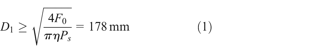
where
2. Calculation of the thickness of Stage 1 cylinder’s wall
According to material strength formula, the calculation formula for the thickness
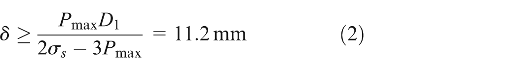
where
The thicknesses of the cylinder walls of each stage are set to 20mm because hydraulic circuits need to be punched in the walls of the multi-stage hydraulic cylinder.
3. Calculation of the diameter of Stage 1 piston rod
In the erecting system, the piston rod bears most of the extrusive or tensile loads in the axial direction; therefore, the calculation of the piston rod diameter should be in accordance with the check formulas for tensile and compressive strengths. Additionally, in order to reduce the weight of the hydraulic cylinder, the piston rod contains a cavity with a diameter of
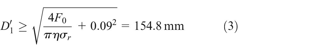
where
4. The internal diameters and thicknesses of Stage 2, 3, and 4 cylinders
The basic size parameters of the TIP multi-stage hydraulic cylinder are determined by referring to Stage 1 and the calculation results as shown in Table 1.
Basic size parameter calculation results.

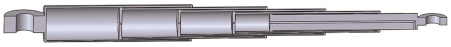
The three-dimensional (3D) model diagram of TIP multi-stage hydraulic cylinder is established by the above size parameters, as shown in Figure 2, and its section is shown in Figure 3.

3D model diagram of TIP multi-stage hydraulic cylinder.
Section of TIP multi-stage hydraulic cylinder.
Mathematical models of TIP multi-stage hydraulic cylinder
Dynamics of pistons
The dynamical model of the multi-stage hydraulic cylinder is normally constructed on the basis of the dynamic theory of multi-rigid-body system, and the pistons are considered as the equivalent of rigid bodies hinged together. In addition, the internal impact process when the stages are switched can be described as the states of “impact” and “recovery.” The impact process involves elastic force, thus resulting in energy loss; therefore, the internal impact process can be described as the model of “equivalent springs + damping force.” Thus, the dynamic differential equations for pistons of all stages are given as 11
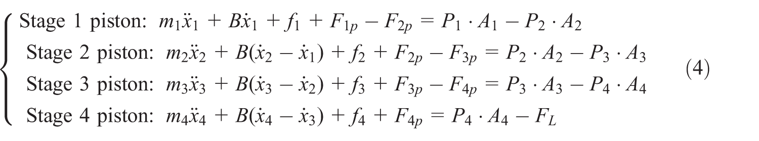
where
A logic function is introduced to describe the presence or absence of impact between objects, and the impact force can be described as


where E is a logic function, and
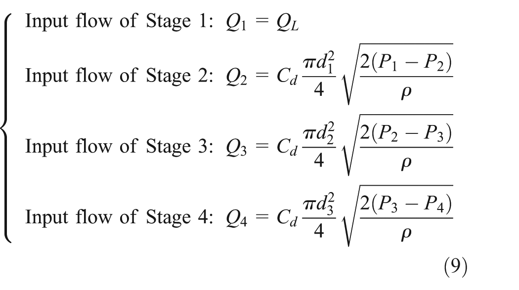
Pressure-flow relationship of piston chambers
The pressure-flow relationship of piston chambers in the TIP multi-stage hydraulic cylinder can be described as 12

where
Orifice throttling equations
The orifice throttling equations are as follows
where
Load model during erecting process
In the erecting process, multi-stage hydraulic cylinder transits the missile from horizontal position to vertical position, which leads to the constant change in the load on the hydraulic cylinder. During this process, the stress-angle relationship is shown in Figure 4.

Force-angle relationship during load rotation around the axis.
The load torque balance function is as follows

where m is the total mass of the missile load, J represents the load’s moment of inertia,

From equation (11), we can find that if the
Orifice diameter optimization
After the basic structure and size of the TIP multi-stage hydraulic cylinder are determined, the diameters of the orifices within the pistons need to be optimized, in order to account for the rapid, steady extension of the multi-stage hydraulic cylinder.
The optimization problem can be described as13,14
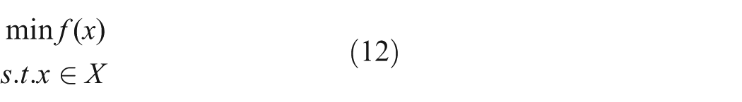
where

where E and I, respectively, represent the equality constraint index set and the inequality constraint index set in the constraint optimization problem, and
The initial conditions for the dynamic equations of pressure-flow equations and orifice throttling equations of multi-stage hydraulic cylinder are chosen as
The piston displacements of all stages in the multi-stage hydraulic cylinder can be expressed as
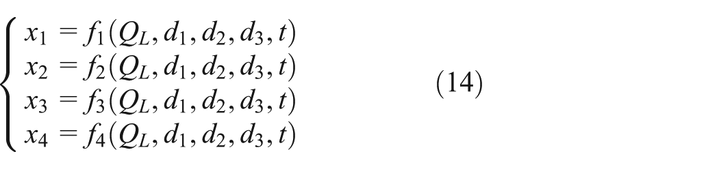
The piston velocities and accelerations of all stages can be obtained based on the displacement expression (14). The total displacement of the multi-stage hydraulic cylinder, that is, the displacement of Stage 4 piston, can be expressed as

Then, the total acceleration of the multi-stage hydraulic cylinder is

The displacements, velocities, and accelerations of the pistons of all stages are the functions about the input flow

The total stroke of the multi-stage hydraulic cylinder is 6.8 m, thus the constraint conditions for the displacements of pistons of all stages are

The total volume of the piston chambers of TIP multi-stage hydraulic cylinder is 334 L, and the input flow

The extension control process of TIP multi-stage hydraulic cylinder is divided into the acceleration phase, the constant flow phase, and the deceleration phase. In the constant flow phase, the load accelerations are varied and cannot be controlled through controlling the quantity of the input flow, under the condition of different flow quantities and orifice diameters; thus, the input flow should be optimized. According to the steadiness requirement for multi-stage hydraulic cylinder, the constraint condition for the steadiness is

Finally, the constraint optimization problem of orifice diameters in the TIP multi-stage hydraulic cylinder is expressed as

Under the condition of the maximum input flow
Numerical simulation and performance comparison
Numerical simulation model setup
In order to analysis performance of the proposed TIP multi-stage hydraulic cylinder, the numerical simulation model of multi-stage hydraulic cylinder is utilized, along with the AMESim simulation software.
The control system model of TIP multi-stage hydraulic cylinder is established and controlled by flow-control valve. Furthermore, the variable load model is also constructed according to equation (11), because the load on the multi-stage cylinder changes during erecting process. Finally, the control system model of the cylinder and the variable load model are jointly formed using the AMESim software, as shown in Figure 5.

Control system model of the cylinder and the variable load model.
The parameters of the TIP multi-stage hydraulic cylinder in the simulation are found, as shown in Table 2.
Parameters of the TIP multi-stage hydraulic cylinder.

Performance comparison with the traditional multi-stage hydraulic cylinder
The performances of the traditional sequential multi-stage hydraulic cylinder and the TIP multi-stage hydraulic cylinder are compared in this simulation, using the same structure parameters and the same input flow of
First, the simulation results of the traditional sequential multi-stage hydraulic cylinder is given in Figure 6, which includes the hydraulic cylinder’s total displacement, the hydraulic cylinder’s overall velocity, the load acceleration, and the relative displacements of pistons of four stages. The simulation results show that the extension duration of the traditional multi-stage hydraulic cylinder is around 100 s, and that its maximum acceleration is up to 25 m/s2.

Performance of traditional multi-stage hydraulic cylinder with input flow 280 L/min.
When the input flow
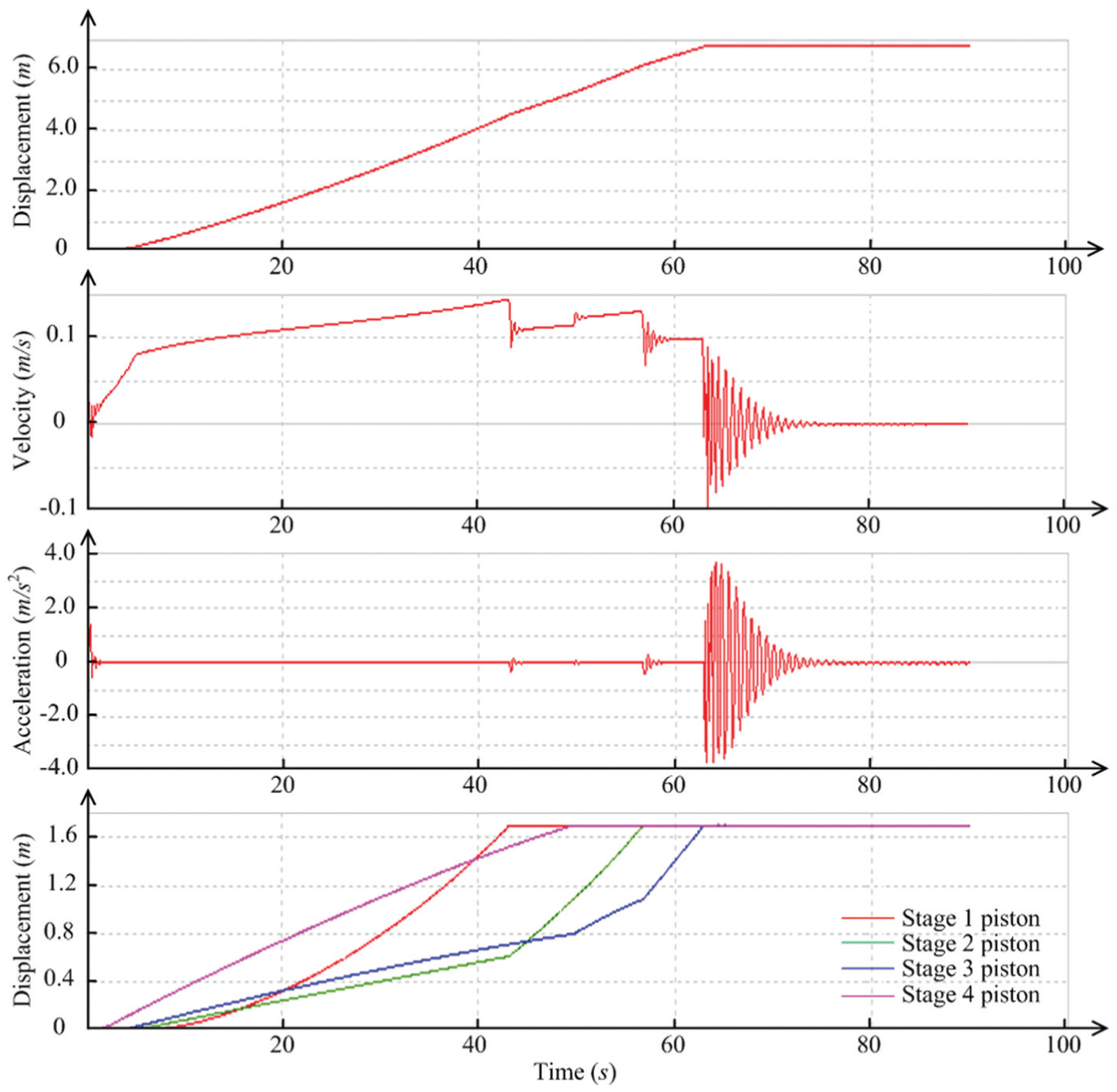
Performance of TIP multi-stage hydraulic cylinder with input flow 280 L/min.
According to Figure 7, the load on the hydraulic cylinder gradually declines, and the velocity of Stage 1 piston quickly rises with the increase in the multi-stage hydraulic cylinder’s displacement. The Stage 1 piston starts last but arrives first at the stroke end, as it has the fastest response to load change. The total extension duration is around 70 s, and the maximum acceleration is 3.7 m/s2. Furthermore, the synchronous extension of pistons is ensured under this normal working condition with the input flow
The comparison indicates that the new type of TIP multi-stage hydraulic cylinder can better ensure the rapid extension of the hydraulic cylinder, effectively shortening the total extension duration, reducing the impact, and stabilizing the operation.
In order to further analyze the effect of different input flows on the extension sequence and rapidity of the TIP multi-stage hydraulic cylinder, the simulations with different input flows are then carried out.
When the input flow is 210 L/min, the performance simulation of TIP multi-stage hydraulic cylinder is conducted and the results, including the hydraulic cylinder’s total displacement, the hydraulic cylinder’s overall velocity, the load acceleration, and the relative displacements of pistons of four stages, are shown in Figure 8.

Performance of TIP multi-stage hydraulic cylinder with input flow 210 L/min.
According to Figure 8, the pistons in the hydraulic cylinder extend sequentially from Stage 4 to Stage 1. The load’s maximum acceleration is 1.8 m/s2 when the hydraulic cylinder started to move. The total extension duration is around 80 s, and the maximum acceleration is 6.5 m/s2.
The performance simulation of TIP multi-stage hydraulic cylinder is conducted when the input flow is 140 L/min and the results are shown in Figure 9.

Performance of TIP multi-stage hydraulic cylinder with input flow 140 L/min.
Since the input flow is too small, the pressures in Stage 1 and Stage 2 piston chambers are not enough to push the pistons out when the hydraulic cylinder starts to move, according to Figure 9. The total extension duration is 97 s, and the maximum acceleration is 6.0 m/s2 under these work conditions.
To sum up, the above performance simulations with TIP multi-stage hydraulic cylinder with different input flows show that the input flow could influence the dynamic performance of the multi-stage hydraulic, and the higher input flow leads to better dynamic performance. With the input flow of
The proposed novel TIP multi-stage hydraulic cylinder can achieve rapid and steady extension; however, some undesired oscillations are found at the ending phase of extension of TIP multi-stage hydraulic cylinder. These oscillations may be eliminated by installing some vibration-isolating rubbers at the bottoms of the cylinders. On the other side, open-loop control strategy with constant input flow is applied in this study. Actually, many advanced closed-loop control strategies11,12,15,16 have been widely researched for hydraulic control systems and many relevant control strategies could be utilized to eliminate the undesired oscillation phenomenon and to further improve the dynamic performance of the proposed TIP multi-stage hydraulic cylinder.
Conclusion
In this article, a novel structure of TIP multi-stage hydraulic cylinder is proposed. The internal structure is adjusted by optimizing the orifice size and flow channel for hydraulic oil, which results in dynamic performance improvement. The diameters of the orifices in the TIP multi-stage hydraulic cylinder are optimized using constraint optimization technique. The new type of TIP multi-stage hydraulic cylinder can significantly enhance the rapidity and steadiness for the erecting system, according to the performance simulation results compared with the traditional sequential multi-stage hydraulic cylinder.
Footnotes
Academic Editor: Pietro Scandura
Declaration of conflicting interests
The author(s) declared no potential conflicts of interest with respect to the research, authorship, and/or publication of this article.
Funding
The author(s) disclosed receipt of the following financial support for the research, authorship, and/or publication of this article: This work was supported by the National Natural Science Foundation of China (grant no. 51305011), the National Basic Research Program of China (973 Program; grant no. 2014CB046402), and the Program 111 of China.