
Abstract
With the widespread use of the vehicle-mounted missile launching system, the research of launch site ground becomes very important. The loading of missile launch system under the supporting disk is similar to inverted bell, and its radius and size of the missile launching are much more than a car. So the ready-made equivalent modulus formula under the action of circular uniformly distributed loading is not suitable for the calculation of launch site ground of vehicle-mounted missile. Therefore, based on the elastic layered system and the Gauss–Legendre numerical calculation method, a new calculation method of equivalent modulus is proposed, as well as the regression formulation for calculation of equivalent modulus of foundation is also shown. Based on the above analysis, a launch site ground mechanical model is presented. The thin plate model on elastic half-space foundation was formulated taking into account normal direction and the double-layer elastic system model was proposed for in tangential direction. Validity of the model was done by coring the programming calculation with the finite element numerical simulation for selected cases.
Keywords
Introduction
With the development of detection technology and the increasing of precision strike capability, weapon system’s survival ability is becoming very important. Fast-moving launch system will undoubtedly improve the weapon system survivability. For trajectory missile, fast-moving missile launch system is more flexible than underground Wells launch system, which can move quickly in a short period of time from one position to another position. Fast-moving missile launch system has two ways, which are railway launch system and vehicle-mounted launch system. With the size of missile becoming smaller and smaller and the improvement of transportation equipment performance, vehicle-mounted launch system received more attention.
In the process of vehicle-mounted launch, constraint force fluctuations from ground to launch platform will cause strong vibration of components, which will affect the precision of a missile launch, seriously threatens the safety of launch. But, in the field of weapon launch presently, launch site ground model mainly focused on the soil model.1–3 Proposed methods are not suitable for rigid concrete ground having layered structure. Therefore, based on elastic half-space foundation model and elastic layered system theory, this article reports the launch site ground mechanical model.
Equivalent modulus of the launch site ground
Model description
In the calculation of the deflection of the field vehicle-mounted launcher system, the elastic foundation plate theory4–7 could be used. The floor structure was regarded as the elastic concrete thin plate surface layer and the foundation. The supporting layers which were under the foundation were characterized by only one modulus. In order to obtain this modulus, the multilayer structure is equivalent to a homogeneous body (elastic half-space) applying the elastic layer theory. Therefore, the parameter is called the equivalent modulus.
The literature8–10 shows that the calculations of the equivalent modulus are based on the assumption of circular uniformly distributed loads, and the derived formula is only applicable under these conditions. The structure of the launcher supporting disk stiffness is much larger than the field, the loading under the rigid supporting disk is in a shape of inverted bell type and the radius of loading distribution and size of the missile launching are bigger than dimensions of vehicle. Therefore, the existing equivalent formulas for modulus are not suitable for the calculation of the launch site ground. In this section, based on the theory of elastic layered system, the formula for equivalent modulus under the action of rigid supporting disk is considered, which is using equivalent principle deflection. The equivalent modulus regression formula is established by means of a lot of number of calculations, which makes equivalent modulus to reach more accurate and has better extension.
Equivalent modulus of double-layer system
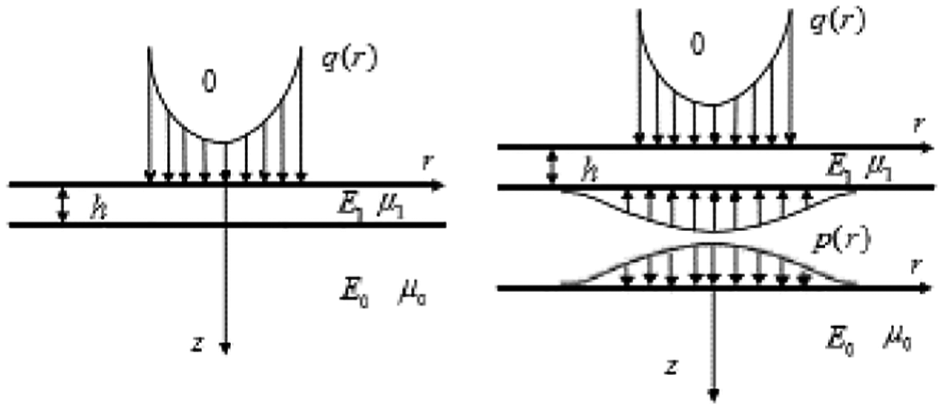
In Figure 1, q(r) represents the loading; h is the upper thickness of the double-layer elastic system;

Double-layer elastic system and elastic half-space body under the rigid supporting disk.
As shown in Figure 1, double-layer elastic system is deflected by the rigid supporting disk. If this layer is considered as an elastic half-space layer,11–13 a deflection value is also obtained under the same load. Equivalent modulus of the foundation could be captured, applying deflection equivalent principle.
Vertical displacement of the elastic half-space system under loading in a form of inverted bell
The formula for the loading represented by inverted bell is expressed as follows 14

where
The Hankel integral transformation was used for the formula (1) and it was integrated into the integral expression of the surface displacement of the elastic half-space

where
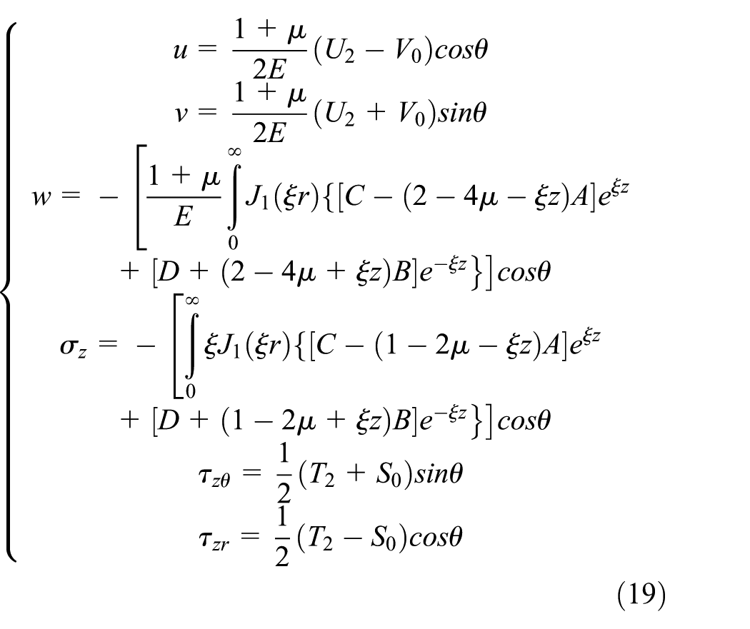
The values of displacements within the zone followed by their radius were equal because of the rigid supporting disk, r = 0, the formula (2). According to the equation

Vertical displacement of the double-layer system under loading in a form of inverted bell
According to the calculations for the elastic layer system,12,15 the deflection value of the double-layer elastic system under the loading represented by equation (1) was determined. The associated items are not presented because of


where
It could be seen that the system of linear equations was quite complex. In this article, the integral coefficients were solved by the symbolic computation in MATLAB. After calculating the coefficients

The establishment of equivalent relation
According to the equivalent principle deflection, the deflection of the elastic half-space system is equal to the deflection of the double-layer elastic system,

where
The relationship between
Examples and methods of validation
We have assumed that the mechanical parameters of two structural layers of the double-layer system were identical, which could be theoretically considered as an elastic half-space. In this way, it was possible to compare the deflection of the elastic half-space and the double layer. Therefore, the correctness of the equivalent parameters could be verified. Their values are listed in Table 1.
Mechanical parameters.

Taking the mechanical parameters in formula (10), the deflection of the double-layer elastic system was obtained

Employing formula (3) at the same values of the parameters considered, the deflection of the elastic half-layer system was also calculated

It could be seen that the two values determined were very close, the error was of −2.09%, expressing that the double-layer elastic equivalent modulus formula is correct.
The regression formula of comprehensive equivalent modulus
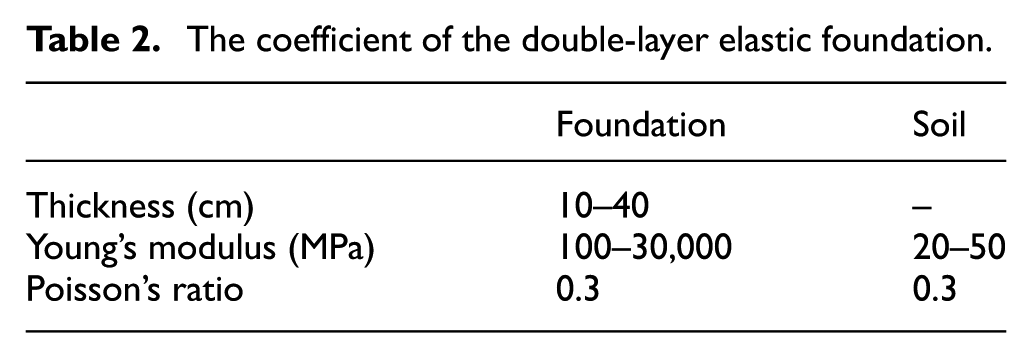
In order to make the calculation to be generality, a large number of rigid concrete fields with different structures are selected for calculation. Since Poisson’s ratio of the material changes little, the effect on the deflection is small. Assume that Poisson’s ratio of the upper and lower layer is consistent. The specific values are shown in Table 2.
The coefficient of the double-layer elastic foundation.
According to the supporting disk’s size of vehicle-mounted missile system and the load characteristics, assume that a radius of 50 cm loading was applied to the launch site ground surface, which form was formula (1) and the stress due to the load and plane was of

where
The fitting coefficient is shown in Table 3.
Fitting coefficients.
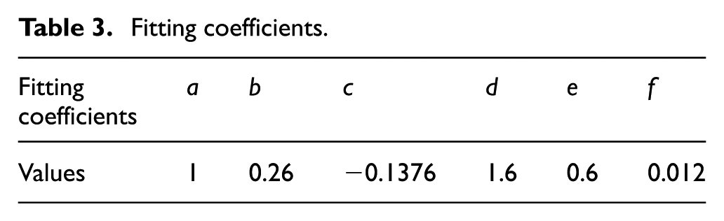
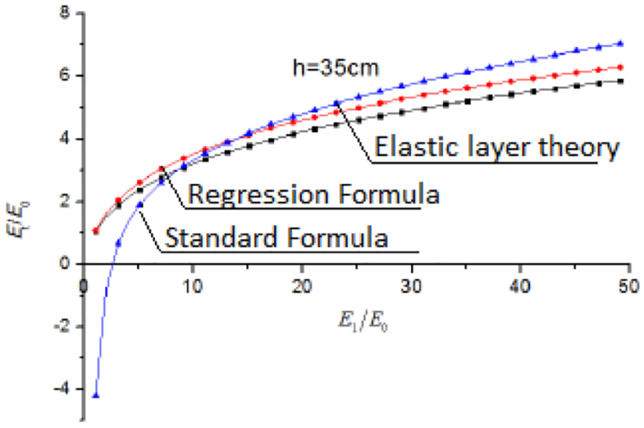
Figure 2 shows the results for the equivalent elastic modulus determined at h = 35 cm. It could be seen from the figure that the method proposed in this article makes up for the deficiency of the equivalent modulus calculated by the standard formula
16
when
Course of proportion of the integrated equivalent modulus for double-layer elastic system.
Mechanics model of launch site ground
There are two types of movement of the launching equipment relative to the launch site ground during the launching process: perpendicular and lateral movements. Therefore, during the launching of the equipment, the surface of the ground is mainly subjected to compression and friction. Under compression, the ground deflects and provides a vertical upward support force; the shear force produces a lateral displacement and provides resistance to movement in the opposite direction.
In the above, the foundation is equivalent to the elastic half-space applying the foundation’s equivalent modulus, then the launch site ground can be seen as a double-layer system. The compression responses of the field under compression and shear force were analyzed, respectively.
Normal motion control equation
Concrete road stiffness under compression is much larger than the foundation layer and the soil stiffness, which had a good ability for spreading the forces. According to the conventional test, it was found that the deflection of the surface layer was small under the loading emission, and the thickness of the surface layer usually reaches the following values 200–300 mm. The deflection of the surface layer was significantly lower than the thickness, so the problem of rigid concrete surface layer can be effectively captured based on the hypothesis of small deflection under typical exploitation conditions. Therefore, the elastic half-space model was adopted for the loading in a form of inverted bell, which can be seen in Figure 3.
The elastic half-space model.
Assuming h,
According to the Kirchhoff layer theory, the following assumptions were made:
The normal line of the layers before and after deformation remains a straight line and perpendicular to the surface.
The normal line of the layers neither elongates nor shortens, and the points are not parallel to the surface displacement.
In the deformation process, the layer and the foundation were always in close contact, the vertical displacement of the top of the foundation and that of the surface layer is equal.
Control equation and integral solution
The differential equation for plate bending is presented in a lot of papers. 17 Using the cylindrical coordinates, the elastic surface equation of the plate is of

where
w(r) and p(r) are unknown quantities. According to the assumptions, the vertical displacement of the foundation top surface was equal to the vertical displacement of the surface layer. From the literature,11–13 the elastic half-space displacement expression under the axisymmetric vertical load is taken as follows

Substituting equation (14) into equation (13), and performing Hankel integral transformation to the final equation, which would get

where
Deflection of the launch site ground under the action of uniform load and loading in a form of inverted bell
Conditions for uniform loading

The formulas (1), (16) Hankel integral transformation, and formula (15) enabled to obtain:
Deflection of the launch site ground under the action of uniform loading

Deflection of the launch site ground under the action of the loading represented by inverted bell shape

Tangential motion control equation
Control equation and integral solution
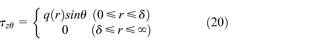
There was an axial symmetry of the role of the unidirectional horizontal loading acted on the ground surface and having radius of δ. There was no loading outside the radius, which can be seen in Figure 4.

The double-layer elastic system with unidirectional horizontal loading.
When m = 1, the expression of the stress and displacement state components of the elastic half-space under axisymmetric circular distribution unidirectional horizontal loading could be obtained
where

Surface stress boundary conditions (z = 0)
In the cylindrical coordinate system, the stress boundary conditions were expressed of


In order to facilitate the calculation, the above expression was rewritten

Using equation (19) in formula (23), and Hankel integral conversion as well as
where
Interlayer bonding conditions (z = h)
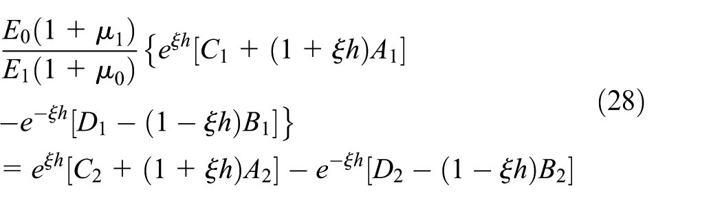
According to the continuous interface assumption, the upper and lower interfaces should have the same stress state, the stress and displacement at the junction are continuous, with the expression described as

The stress and displacement components in formula (19) were introduced in formula (25), and Hankel integral changes were performed on both sides of each equation. By adding or subtracting the equations, six linear equations were obtained


Additional condition of elastic half-space

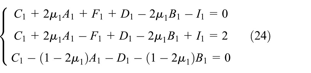
Equations (23), (24), (26)–(32) formed an algebraic system of 12 equations. Through the computation applying symbols, the linear algebraic equations were solved and the integral coefficients of each layer were obtained. As can be seen from the matrix coefficient, the integral coefficient is only related to the intermediate variable ξ, the remaining variables are known. After obtaining the integral coefficient, multiply the Hankel integral of the loading and take it into the formula (19), then the theoretical solution of double-layer system under the uniaxial horizontal load with symmetric circular distribution of the load concentration was obtained.
Tangential displacement of the launch site ground surface under the action of uniform and not uniform loading
(1), (16) Hankel integral transformation, and taken into the tangential control equation of the theoretical solution, z = 0
Deflection of the launch site ground under the action of uniform loading was expressed as follows
Deflection of the launch site ground under the action of loading in a form of inverted bell was presented

Numerical integral method with infinite integral of Bessel function
In the above sections, the expressions of stress and displacement had infinite integral of Bessel oscillation function and exponential function integrals in the solution of elastic half-space and double-layer elastic system, which can only be calculated by numerical integration. There are two types of numerical methods for the theory of elastic layer. One is the Simpson numerical integration method and the other is the Gaussian numerical integration method. In order to verify the accuracy and validity of the numerical method, the following expression should be considered

Taking r = 0.9 and δ = 0.4, the plot of the integrand can be reached as shown in Figure 4.
It could be seen from Figure 5 that the integrand with two Bessel functions was oscillatory and rapidly reached zero. At ξ = 6, the value of the integrand is diminished up to −9.879e–5, and while the upper limit

The plot of the integrand function.
In order to compare the computational efficiency of the Gauss–Legendre integral and the Simpson integral for solving the launch site ground problem, numerical integration of the expression (36) was performed using the two methods. The results were shown in Table 4.
Integration results of Simpson and Gauss–Legendre method.

As can be seen from Table 4, when the number of nodes was 30, the approximate value of Simpson’s integral method began to be stable, and the number of calculations was close to 90 times. When the number of nodes reached 15, the approximation of the Gauss–Legendre method began to stabilize, and the number of calculations was 15. It could be seen that the Gauss–Legendre method was superior to the Simpson method with respect to time needed to achieve final results and accuracy. This article adopted Gauss–Legendre numerical integration method.
Model validation
Validity of the model was proved by comparing the programming calculation with the finite element numerical simulation for selected cases. The type of the load was formula (16), while the acting radius of the loading was of δ = 440 mm, and resultant pressure was of
Mechanical parameters of the launch site ground.

PCC: plain cement concrete.
Mechanical parameters of the equivalent launch site ground.

PCC: plain cement concrete.
The normal control equation was determined by MATLAB programming. The finite element calculation was carried out in ABAQUS software. Figure 6 presents a surface deflection curve of the cross section of the field under uniform loading, where the deflection value was negative for down deflection and its value was the theoretical approach for the numerical solution. From the figure, it could be seen that the deflection was dependent on tangential distance, reaching the minimum for the tangential distance of 0 mm. The deflection increased with tangential distance increasing, this is consistent with the results of Johnson. 14 The deflection value of the finite element solution at the load center and the loading edge were 0.385 and 0.32 mm, the deflection value of the theoretical solution at the load center and the loading edge were 0.397 and 0.344 mm. If the finite element numerical solution was used as the reference, the calculation errors of the center and the edge were 0.462% and 7.5%, respectively, which indicates on small differences.
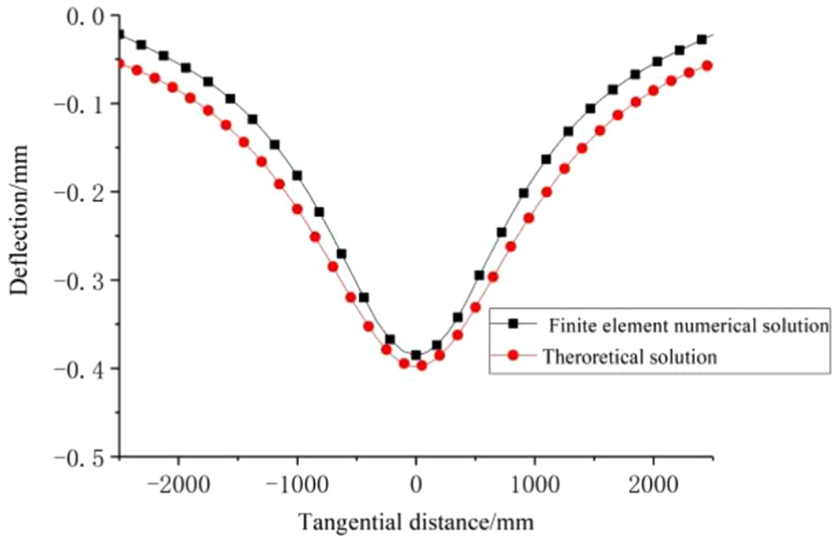
Deflection of the launch site ground under uniform loading.
Figure 7 shows a three-dimensional (3D) shell view of the ground deflection calculated by MATLAB. Figure 8 illustrates 3D deformation diagram from the finite element numerical calculation. From the surface of the floor, deformation map could be more intuitive to see that both were axisymmetric deformation.

A shell of the ground deflection in 3D coordinate system.

The ground deflection in 3D coordinate system.
Conclusion
The main work of this article is to build the mechanics model of launch site ground.
Based on the features of the contact structure between the supporting disk and the launch site ground, the equivalent modulus calculation method of the elastic layer system was elaborated and verified. The calculation program of the equivalent modulus of the foundation of the launch site ground was compiled. The regression formula for the modulus was obtained employing a large number of different structures.
Based on the above analysis and according to the characteristics of the launching equipment relative and the launch site ground, the mechanical model of the launch site ground was proposed. The elastic half-space elastic model and the elastic double-layer model were established in the normal direction and tangential direction, respectively. The deflection of the ground under a symmetrical uniform loading was calculated and compared with the results obtained by the use of ABAQUS software. The results showed that the calculation errors for the theoretical solution were 0.462% and 7.5%, respectively.
Footnotes
Handling Editor: Michal Kuciej
Data availability statement
The data used to support the findings of this study are included within the article.
Declaration of conflicting interests
The author(s) declared no potential conflicts of interest with respect to the research, authorship, and/or publication of this article.
Funding
The author(s) received no financial support for the research, authorship, and/or publication of this article.