
Abstract
In view of the mission of the cooperative target capture with the space manipulator, this article proposes to establish pose measurement model of the space cooperative target capture based on thick lens model for the first time. First, a ground simulation system is established for the cooperative target capture with the space manipulator based on the zoom vision system, coordinate system is defined, and pose calculation process is given. Then, space coordinate measurement model and pose calculation model are established for the system. Finally, the simulation experiments are conducted and the results validate the algorithm model and the high accuracy of measurement.
Introduction
In recent years, target pose measurement has become a research hotspot1–3 and is potentially useful in more fields.4–9 As the space mission becomes more complicated and diversified, the computer vision–based space manipulator system is more applied to space missions.10–14 However, it is difficult for traditional fixed-focus camera to maintain a high image resolution in the whole motion process of the space manipulator and cooperative target,15–17 and the measurement accuracy will be affected accordingly. That is one of the major challenges for accomplishing the above space mission with the computer vision–based system.
On the other hand, the application of multiple fixed-focus cameras to capture overall targets in space mission will result in increased complexity of the mechanism, decreased robustness, and more space energy consumption, bringing great loads to the spacecraft body. Therefore, it is evident that extensive application of the zoom vision–based space manipulator will show important values.
As early as in 1990, J Ma and S Olsen 18 proved that the zoom lens can be used to obtain depth information of the measured target. On this basis, JM Lavest et al. 19 and their vision team carried out further researches and proved that the thick lens model is an ideal model for the zoom camera. In the subsequent studies, the team systematically explicated the difficulties in the calibration of vision measurement system.20–23 In 2000, Y-S Chen et al. 24 from National Taiwan University proposed a simple and effective method of calibrating electric zoom cameras’ internal parameters. In 2001, a laboratory, CVIP at the University of Louisville, calibrated the zoom camera parameters using neural network method. 25 In 2009, M Sarkis et al. 26 from Technical University of Munich (Germany) calibrated automatic zoom camera using the least square method. In 2010, the Health Science College of Milwaukee University (USA) and the Broadcasting Institute of Technology of Yonsei University (Korea) jointly corrected the radial distortion of the automatic zoom camera. 27 In 2012, L Alvarez et al. 28 of ULPGC University (Spain) proposed a new mathematical model to study the lens distortion when the focal length of the zoom lens changes. In the same year, H Gao et al. 29 of Shenyang Ligong University (China) calibrated zoom center of image plane. In 2013, J Kang et al. 30 from Institute of KBS (Korea) put forward a kind of optical axis compensation method based on the binocular zoom camera.
The major contributions of this article are as follows. In view of the mission of the cooperative target capture with the space manipulator on the space station, the hardware-in-the-loop (HWIL) simulation experimental system is set up in this article. Considering the imaging principle, thick lens model is introduced to present the imaging relation of the zoom camera. Pose measurement model is established for the space cooperative target capture based on the zoom vision system, and the simulation is conducted to validate the model.
Space monocular zoom visual system
System composition
According to the real mission of the space manipulator in on-orbit service, a simulation experiment system is established on the ground, as shown in Figure 1.
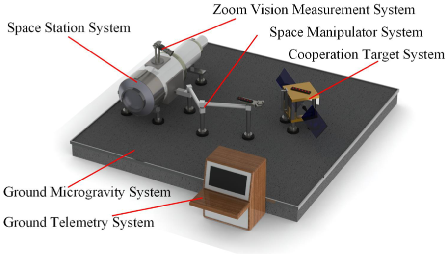
System composition.
In Figure 1, the system consists of six parts: ground microgravity system, space station, space manipulator, zoom vision system, cooperative target, and ground telemetry system. The camera of the zoom vision system is located above the base of the space station, the space manipulator marker is located at the end effector, and the cooperative target marker is located at the cooperative target. When the space manipulator executes the cooperative target capture mission, the ground telemetry system will send commands to each system, while the zoom vision system will calculate the pose information of the end effector of the manipulator and the captured mechanism of cooperative target, and the space station will program the trace of the space manipulator according to the commands to capture cooperative target. On the ground, the system can achieve free floating state of the space manipulator and cooperative target, complete target grabbing, and releasing tests for the manipulator.
Visual measurement coordinate system
The coordinate systems are defined for the measurement model of the system based on the structure of the simulation experiment system, as shown in Figure 2.

Visual measurement coordinate system.
In Figure 2, the system contains world coordinate system
Calculation process of pose measurement
When the space manipulator executes the cooperative capture mission, it is proposed to define the pose of the end effector of the space manipulator in the world coordination system, define the pose of the captured mechanism of the cooperative target in the world coordinate system, and accordingly define the pose correlation between the end effector and the captured mechanism. Figure 3 demonstrates the calculation process.
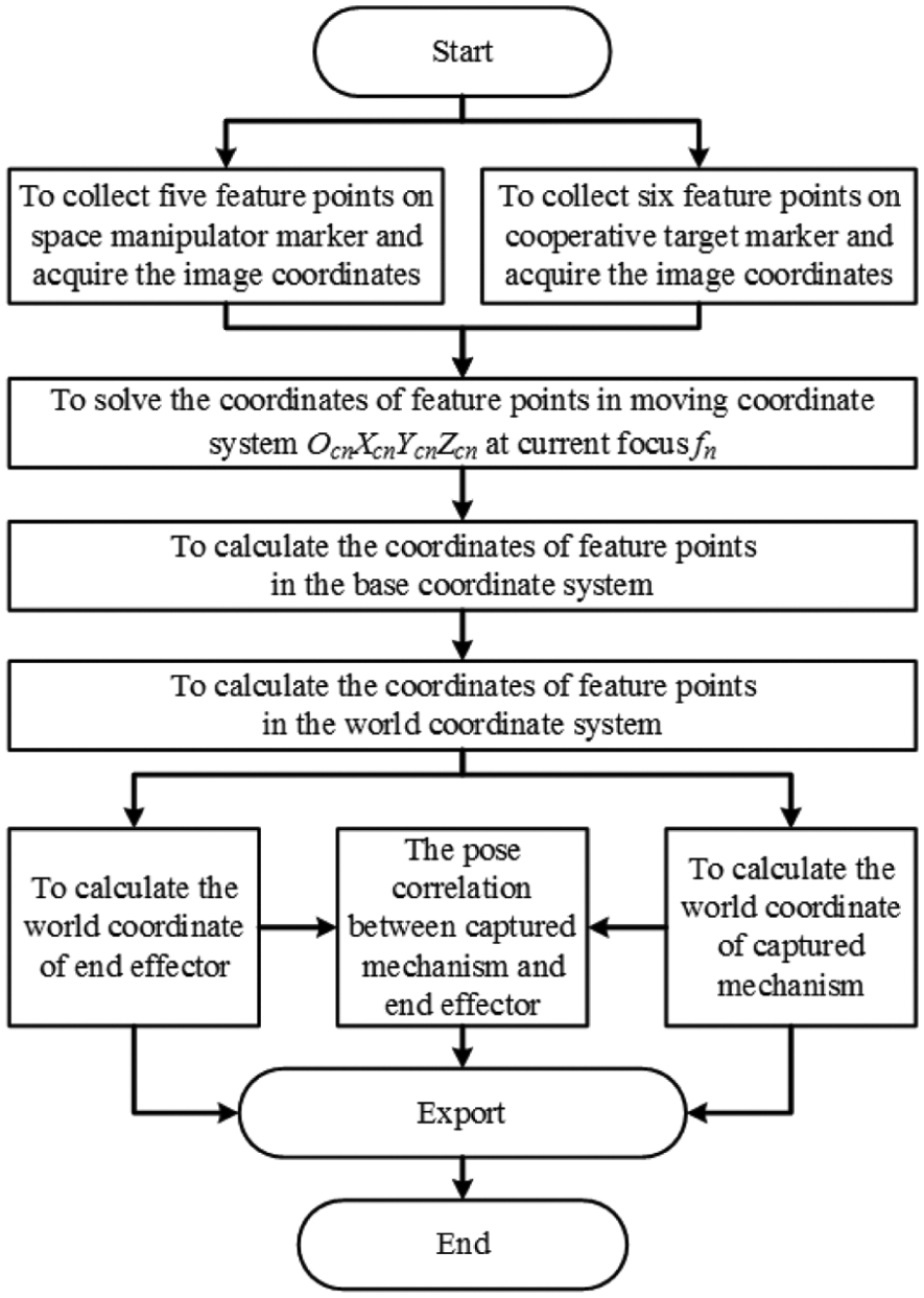
Process of pose measurement.
First, to place the zoom camera above the space station to collect five feature points on the space manipulator marker and six feature points on the cooperative target marker and acquire the corresponding image coordinates. Then, to solve the coordinates of the feature points in moving coordinate system
Pose measurement model
Thick lens model
In space measurement missions, the zoom camera is hardly applied, because its internal and external parameters change with focal length, and such change can greatly increase the fluctuation in pose measurement. Studies show that thick lens model is considered the ideal for zoom lens. By establishing zoom camera model based on thick lens model and applying the model to space measurement missions, the disadvantage of pinhole camera can be overcome.
As shown in Figure 4,

Thick lens model.
Zoom coordinate measuring model
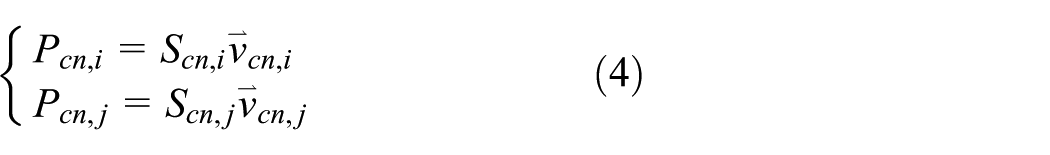
According to Figure 3, in zoom camera measurement system, it is required to establish the imaging correlation between the zoom camera and manipulator marker feature points and the imaging correlation between the camera and cooperative marker feature points. See Figure 5 for image correlation of two feature points.

The relationship between image coordinate system and camera moving coordinate system.
In Figure 5,
From perspective imaging correlation, equation (1) is obtained as

The angle

where

The 3D coordinates of the feature points in the camera coordinate system are expressed as
In

Considering the research requirements on the cooperative target capture with the manipulator in the space station, five feature points are established for the space manipulator marker and six feature points for the cooperative target marker. Therefore,

Pose solution model
The transform correlation of the space feature points and the zoom camera moving coordinate system can be known from section “Zoom coordinate measuring model.” Set the coordinates of the feature points on the manipulator marker as

where
Suppose the coordinates of the space feature points on the end effector marker are

where
Then, the coordinates of the space feature points on the manipulator marker and cooperative target marker can be transformed from

where
To establish correlation between the space manipulator end effector in the world coordinate system, the coordinate transformation between the end effector and space manipulator marker shall be known. Set the coordinates to be

where
Thus, the coordinates of the manipulator end effector and captured mechanism of cooperative target can be obtained as

where
Finally, the relation between the captured mechanism of the cooperative target and space manipulator end effector can be expressed as

where
Simulation and analysis
Main simulation conditions
Condition 1. Camera pixel resolution: 1400 × 1024; principal point position: u0 = 700, v0 = 512; pixel size: 7.4 µm × 7.4 µm; zoom lens focus range: 16–64 mm; camera at focus f = 24.
Condition 2.
Condition 3. Set the transformation correlation between the end effector coordinate system and captured mechanism coordinate system as follows: the translation in three directions is
Simulation steps
Step 1. To generate image points of each feature point and apply noise of 0.03, 0.1, and 0.3 pixel standard deviation, respectively.
Step 2. To solve the coordinates
Step 3. To solve
Step 4. To obtain the feature point coordinates
Step 5. To obtain the feature point coordinates
Step 6. To obtain
Step 7. To calculate attitude matrix
Simulation experiments
The sub-pixel location technique will be applied in the actual system, and 0.03, 0.1, and 0.3 pixel are the typical standard deviations for such location. Therefore, the corresponding noise level is assumed in the simulation.
Figures 6 and 7 show the 6 degree-of-freedom (DOF) errors at 0.03 pixel standard deviation. In Figure 6, the attitude error results of x-, y-, and z-axes are given, respectively, by three curves. Among them, the z-axis attitude error is less than 0.01°, which is better than x- and y-axes. In Figure 7, the translation error results of x-, y-, and z-axes are given, respectively, by three curves. It can be seen that the x-axis and y-axis translation error is less than 0.02 mm.

The attitude error in 0.03 pixel standard deviation.

The translation error in 0.03 pixel standard deviation.
Figures 8 and 9 show the 6-DOF errors at 0.1 pixel standard deviation. In Figure 8, the attitude error results of x-, y-, and z-axes are given, respectively, by three curves. Among them, the z-axis attitude error is less than 0.03°, which is better than x- and y-axes. In Figure 9, the translation error results of x-, y-, and z-axes are given, respectively, by three curves. It can be seen that the x-axis and y-axis translation error is less than 0.6 mm.

The attitude error in 0.1 pixel standard deviation.
The translation error in 0.1 pixel standard deviation.
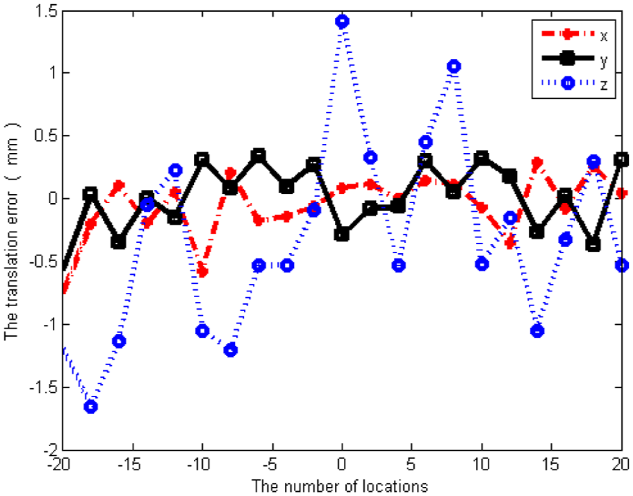
Figures 10 and 11 show the 6-DOF errors at 0.3 pixel standard deviation. In Figure 10, the attitude error results of x-, y-, and z-axes are given, respectively, by three curves. Among them, the z-axis attitude error is less than 0.1°, which is better than x- and y-axes. In Figure 11, the translation error results of x-, y-, and z-axes are given, respectively, by three curves. It can be seen that the x-axis and y-axis translation error is less than 1.5 mm.

The attitude error in 0.3 pixel standard deviation.
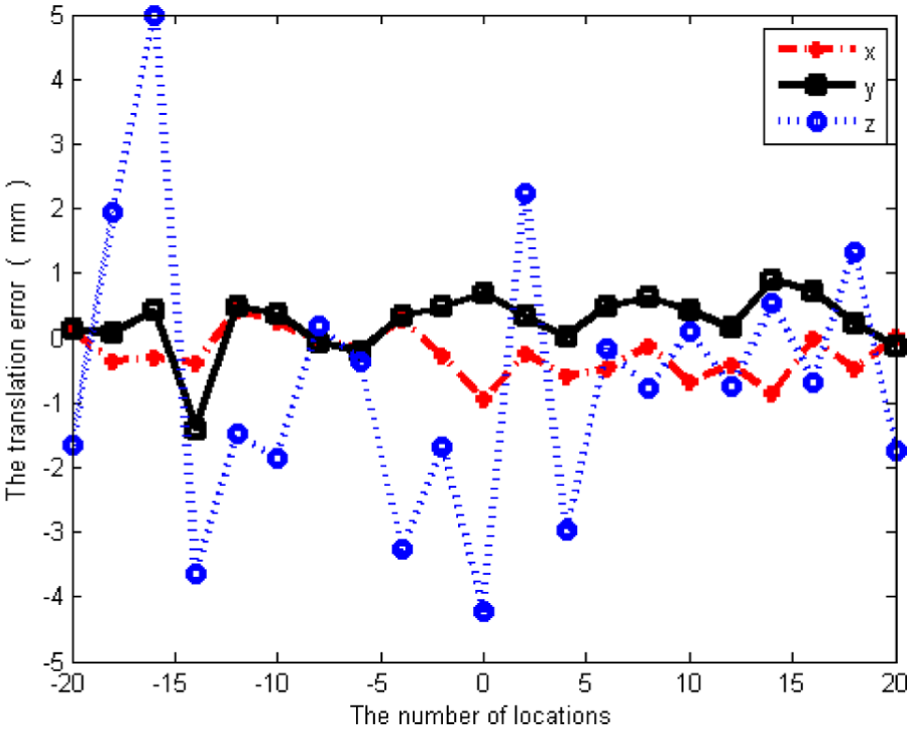
The translation error in 0.3 pixel standard deviation.
Overall, the maximum angle error is 0.04° and the maximum displacement error is 0.6 mm at 0.03 pixel standard deviation. The maximum angle error is 0.15° and the maximum displacement error is 2.0 mm at 0.1 pixel standard deviation. The maximum angle error is 0.8° and the maximum displacement error is 5.0 mm at 0.1 pixel standard deviation. The angle error of 1.2° and the displacement error of 8 mm is allowed in space missions, so the results are acceptable.
Conclusion
This article proposes a pose measurement model for the cooperative target capture with the space manipulator based on the zoom vision system. A zoom coordinate measurement model is established based on thick lens model to complete the pose solution model. Finally, simulation experiments are conducted to validate the model, and the results show that the maximum angle error is 0.04° and the maximum displacement error is 0.6 mm at 0.03 pixel standard deviation, the maximum angle error is 0.15° and the maximum displacement error is 2.0 mm at 0.1 pixel standard deviation, and the maximum angle error is 0.8° and the maximum displacement error is 5.0 mm at 0.3 pixel standard deviation, all of which are within the tolerance. The model established herein will play an instructive and reference role in the space target measurement mission.
Footnotes
Academic Editor: Nasim Ullah
Declaration of conflicting interests
The author(s) declared no potential conflicts of interest with respect to the research, authorship, and/or publication of this article.
Funding
The author(s) disclosed receipt of the following financial support for the research, authorship, and/or publication of this article: This work was supported by National Natural Science Foundation of China under grant no. 61171189.