
Abstract
The article describes the measurement of unidirectional pose accuracy and repeatability of a collaborative robot. The objective of the measurements is to investigate and evaluate unidirectional accuracy of the six-axis collaborative robot UR5 of the company Universal Robots. The measurement methodology was based on outlining an imaginary ISO cube placed in the robot’s workspace, in which the robot’s tool centre point (TCP) attained five measurement points in thirty measurement cycles. A video camera and six linear incremental sensors with six evaluation units were used for the measurement. The measured values are presented and applied according to the ISO 9283 standard. On the basis of the measurement, we verified technical specifications of unidirectional pose accuracy and repeatability of the robotic arm UR5 specified by its producer.
Keywords
Introduction
Due to the current pressure on required accuracy in production as well as efficiency and reliability of automated and robotic lines, a need arises to conduct many scientific studies and tests focused on the accuracy of such equipment and on the correct approach to its programming. In the case of industrial and collaborative robots, their accuracy and repeatability are some of the most important properties influencing the operation and running of production equipment in the production. Accuracy is understood to be the ability to attain the required point in the workspace. One of the basic methods of determining accuracy is the measurement of angular or linear changes of individual parts of the robot. Repeatability is the ability of the robot’s arm to return to the same position from the same direction, by which the effects of play are minimised. It is therefore the robot’s ability to attain the required position with respect to its reference position. The pose accuracy is influenced by the wear in joints, gear transmission errors, friction, workspace, assembly, static and dynamic factors, and many other factors affecting the operation of the equipment.
Besides their basic technical characteristics, which include the payload, number of degrees of freedom, shape of the workspace and other, industrial robots are also specified by operational characteristics. The ISO 9283 (1998) standard defines four basic types of operational characteristics 1 :
pose characteristics,
path characteristics,
minimum positioning time,
static compliance.
Out of the operational characteristics described by the standard (ISO 9283, 1998), leading world manufacturers of industrial robots specify in their technical documentation for robots only the pose repeatability RP. They also inform about the possibility of application, payload, shape and size of the workspace or the range of turn angles and speeds of individual axes of a specific type of robot. In the case of robot manufacturers who focus only on some specific applications of robots, for example, only the field of welding, there is a chance that they will specify in the technical documentation multiple operational characteristics related to the application for which the robot was designed.
The significance of operational characteristics differs according to the application a specific robot functions. For example, for a robot performing a coating application in the automotive industry, the most important operational characteristics will be related with the path, accuracy and velocity. Besides the specification of individual operational characteristics and the way of their measurement, the standard (ISO 9283, 1998) also recommends the selection of the most important ones on the basis of several typical applications of the robot. In each case, the operational characteristics allow a detailed view of the robot’ properties influencing its work in a specific application.
The above-mentioned standard does not specify which of the mentioned operational characteristics should be used for the testing of a specific robot. The tests described in this standard focus in particular on the development and verification of individual specifications of the robot, but may also be used for other purposes, such as a prototype test, a type test, or an acceptance test. This standard applies to all manipulating industrial robots defined in accordance with ISO/TR 8373.
For the purposes of this standard, definitions established in ISO/TR 8373 and the following definitions are used:


Set of attained positions.
The objective of this article is to verify the unidirectional pose accuracy of the UR5 robot with the provided technical specification from the manufacturer by means of the described measurement method and to subsequently process and present the obtained measurement results.
State of art
A number of authors in many significant publications currently deal with the issue of measuring unidirectional pose accuracy of robots. The authors of the article ‘Assessment of the positioning performance of an industrial robot’ analyse the pose accuracy of a non-calibrated robot ABB IRB1600 by means of several methods and various equipment. They use an experimental approach to the assessment of the static repeatability and static accuracy with the description of geometrical and dynamic errors occurring in the robot’s movement. For the measurement of unidirectional pose accuracy and determining static errors, they used a laser tracker FARO ION for the measurement in five positions along an inclined plane. For additional, more complex, measurement, they used a laser interferometer Renishaw XL80 with the resulting accuracy of the linear position better than 650 μm, while the worst orientation accuracy was approximately 0.16° (2.8 mrad) and with the use of the Renishaw QC20-W telescoping ballbar with the finding that this type of measurement is not sufficient for the assessment of static accuracy and repeatability. 2
A FARO Tracker was also used by Muelaner et al. for the evaluation of repeatability in the measurement of an industrial serial robot KUKA KR240. 3
Marek Płaczek et al. analysed in their article the issue of the measurement of accuracy and repeatability of a robot’s movement by means of the FARO Vantage Laser Tracker. The measurements were done in laboratory premises on a KUKA KR 16-2 robot. They also focused on the comparison of paths of the robot’s movements in the Robcad environment with the use of real paths of the robot’s movements. Their article describes a measurement method and the influence of types of paths and parameters of movements on the accuracy and repeatability of the robot, as well as the accuracy of the mapping of a simulated movement of the robot in a virtual environment. This research is extremely important for the understanding of differences between the accuracy in the programming of the path of a robot’s movements simulated in a real environment in comparison with that in the programming in a virtual environment, done by the simulation on the basis of a program created offline in software. 4
Authors who created a calibration system (3D measurement system) consisting of a CCD camera, mounted on a robot with the objective to measure the position of the end effector with respect to the global coordinate system, studied another solution for the measurement of pose accuracy. The achieved measurement accuracy of the equipment was between 0.2 and 0.4 mm at a distance of 600 to 800 mm from the measurement point. The research team studying this issue presents the results on the basis of tests carried out with two ABB IRB 2400 industrial robots and a PUMA 500 robot with the intention to point to the increase in their accuracy by means of the proposed calibration equipment. The result of their effort was a proved increase in the pose accuracy of the robots when the created device, simple, fast and easy to configure, and efficient in particular, was used. 5
In their paper, the authors deal with the issue of the measurement of pose accuracy of the Fanuc LR Mate 200iC robot with the use of the Renishaw Ballbar QC20-W measuring equipment, which can also be used in the measurement and evaluation of the calibration of a CNC machine tool. As the measurement method, they used a method based on the principle of the creation of a polygonal pseudo-circular path, which allows fast and simple measurement and can be sued in all routine applications of industrial robots. The measurement lies in changes of the radius when making circular trajectories around a fixed point determined by its centre. With the use of additional equipment, radiuses between 50 and 600 mm can be measured, while the obtained data are subsequently processed in the Ballbar 20 software for determining the overall accuracy of a machine, in line with the applicable standards. 6
In their study, the authors proposed a scanning application by means of an X-ray computer thermograph as scanning equipment attached to an industrial robot. To ensure a suitable course of scanning, it was necessary to secure the required image quality. A KUKA KR 15-2 robotic arm, on which the achieved pose accuracy was tested by means of a laser interferometer, was assembled, and the measured deviations were subsequently used for the X-ray simulation by means of Scorpius X-Lab. The investigation resulted in identified errors, shown by the poor image quality and systemic errors up to 1 mm, and it was also found that it was possible to prevent such errors by continuous calibration. 7
There are several other calibration techniques for industrial robots for the needs of improving their accuracy. Industrial robots constantly show systemic and stochastic deviations in their operation. For this reason, several types of methods for the measurement of deviations were created, specifically a sensoric system for the continuous measurement and monitoring of a robots’ positions, for example, by the monitoring of the test sample by means of a camera placed on the robot’s end effector or by means of sensors.8,9
Other approaches in the prevention are continuous calibration of the robot by means of X-rays, laser monitors or by means of the combination of a laser pointer and a camera. Another approach is the establishing of a mathematical model, including rigidness, temperature variations, joint plays and geometrical parameters. Such an approach to prevention is used mainly in machining applications.10–12
Characteristics of the controlled UR5 robot
The Universal Robot UR5 is a robotic arm with six degrees of freedom. The payload of the robot is 5 kg and it has a reach of 860 mm. The maximum speed in the joints of the robot at the setting of 100% movement is 183°/s. Joint limits for all joints (base, shoulder, elbow, Wrist1, Wrist2, Wrist3) can be independently configured in the range of −363° to 363° (deviation ±3°). The robot is designed in particular for the collaboration with the human (Human Robot Collaboration – HRC), which implies the way of its control. In contrast with usual industrial robots, designed for work in an area protected by mechanical barriers, the UR5 control monitors the forces on individual axes and it stops the robot in the event they are excessive. Besides that, it is also possible to set bands (levels) where the presence of the operator is envisaged. When approaching those bands, the allowed force limits, joint velocities and momenta are reduced.
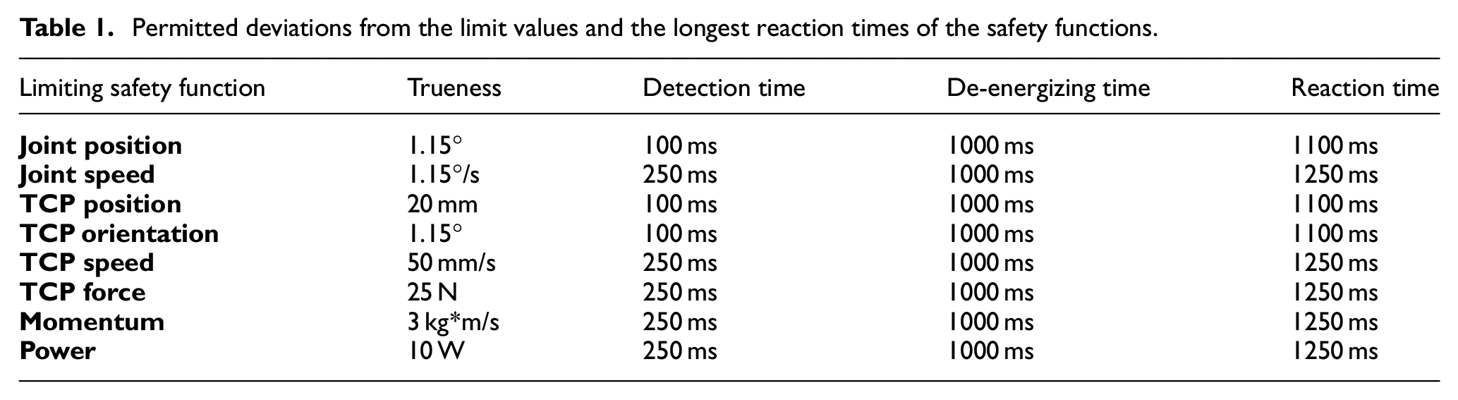
If the robot arm reaches the value of the allowed deviation from the limit of the monitored safety function during the movement along the prescribed trajectory, the robot will reduce the speed or activate the stop function. The values of the deviation from the prescribed values and the longest reaction times of the system given by the manufacturer (Universal Robots, User Manual UR5/CB3, Original instructions, 2016) are in Table 1.
Permitted deviations from the limit values and the longest reaction times of the safety functions.
The UR5 robot has simpler programming than usual industrial robots, so its adjustment can be managed even by a less qualified person. On the other hand, the initial commissioning of the robot requires risk assessment. It is then necessary to make the basic setting of the robot’s safety functions on its basis, which is work for a qualified integrator.
The robot consists of three basic parts:
Robotic arm
Control box – robotic controller
Control panel (Teach Pendant)
The robot’s arm contains integrated joint drives, housing a reduction gear, a motor, a drive, a position sensor and a brake.
Kinematic and dynamic parameters of the robot
For robots of the company Universal Robots there is a community support for the connection to a robot operating system ROS. The ROS offers the possibility to control the path in joint coordinates, interpolation, to adjust digital outputs, and to monitor joint coordinates, forces acting on the effector and the state of the digital inputs. ROS offers the possibility of implementing the model into the MoveIt program (Figure 2), which can generate trajectories with treatment of self-collision states and conversion into joint coordinates. The ROS interface uses its real-time protocol for the communication with the robot’s control system.

Trajectory planning environment in ROS.
Interpolation is the process of defining a function that passes through specified points according to certain values. With PTP (point-to-point) motion, the motion starts and ends for all axes simultaneously. PTP mode is used for preparatory movements, where it is required to move the robot to the desired position as quickly as possible. When moving the robot to the required points, it is possible to apply an approximation that will allow smoother movement without unnecessary slowdowns. In this case, the path of movement of the robot arm cannot be determined in advance. Endpoints are defined to which the robot arrives exactly or bypasses them when setting the approximation parameter. If you need to guide the path in the desired direction, you can move the arm of the Universal UR5 robot using MoveJ (move in a straight line), MoveL (linear movement), MoveP (linear movement with constant speed and rounding) and MoveC (movement in a circle). A more detailed description of the robot’s movements is as follows:
MoveJ is a movement between two path points (movement on a straight path). All joints are controlled to reach the desired position endpoint simultaneously. The necessary parameters used for this type of movement are the maximum joint speed in units of deg/s and its acceleration deg/s2.
MoveL moves the tool linearly between two path points. The necessary parameters for creating this motion are the determination of the tool speed and acceleration in units of mm/s and mm/s2 and the element defining the position of the tool at the path points.
MoveP moves the tool linearly at a constant speed with circular rounding. The amount of fillet is shared by default for all path points. A lower value means a sharper turn; a higher value means a smoother path.
If a MoveC motion is added to the MoveP command, you can create a circular motion. The robot starts the movement from the current position or the starting point, it moves through the auxiliary point (ViaPoint) through the given circular arc to the end point (EndPoint), which complements the circular movement. In this case, the approximation is not applied to the auxiliary point.
It is possible to simulate the robot’s movements and operation in the RViz (ROS) environment and in the Matlab environment. A model of the robot with defined kinematic (Figure 3) and dynamic parameters was assembled on the basis of the robot’s configuration and dimensions.
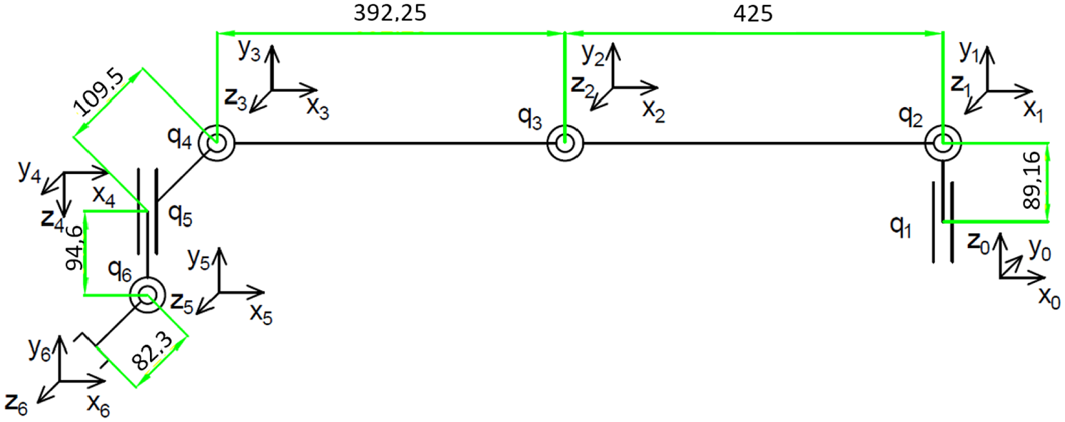
Kinematic parameters of the UR5.
For the computer simulation, it is suitable to describe the robot’s kinematics in the form of D-H parameters (Denavit–Hartenberg parameters), which is used by multiple simulation programs. The kinematic parameters of the UR5 robot written in the D-H form are contained in Table 2.
Kinematic parameters of the UR5 robot in the D-H convention.

The following dynamic parameters result from the kinematic model of the UR5 robot:
The centre of gravity of mass point m1 is at a distance [0; 0.02561; 0.00193] from the x1, y1, z1 coordinate system. The mass of mass point m1 is 3.7 kg.
The centre of gravity of mass point m2 is at a distance [0.2125; 0; 0.11336] from the x2, y2, z2 coordinate system. The mass of mass point m2 is 8.393 kg.
The centre of gravity of mass point m3 is at a distance [0.11993; 0; 0.0265] from the x3, y3, z3 coordinate system. The mass of mass point m3 is 2.275 kg.
The centre of gravity of mass point m4 is at a distance [0; –0.0018; 0.01634] from the x4, y4, z4 coordinate system. The mass of mass point m4 is 1.219 kg.
The centre of gravity of mass point m5 is at a distance [0; 0.0018; 0.01634] from the x5, y5, z5 coordinate system. The mass of mass point m5 is 1.219 kg.
The centre of gravity of mass point m6 is at a distance [0; 0; –0.001159] from the x6, y6, z6 coordinate system. The mass of mass point m6 is 0.1879 kg.
The issue of forward kinematics and inverse kinematics was discussed in more detail in their studies by the research team of Kebria et al. 13 and also by Kovincic et al. 14
Verification of dynamic parameters
Dynamic parameters were implemented into the simulation model in the MATLAB/SimMechanics environment.15,16 The block diagram of the simulation model is shown in Figure 4. A continuous joint path according to Figure 5 was generated for the model.

Simulation diagram of a dynamic model of the UR robot.
Test path of UR5.
On the basis of the model, an inverse dynamics model was created. The accuracy of the parameters was verified by the comparison of the robot’s simulated movements with measured values.
The simulation took place in the system of joint coordinates. An identical path was generated for each joint in the position range between 0 and (–π/2). The results of the simulation show the torques necessary for making the intended movement and are depicted in Figure 6 in the ascending order from joint No 1 to 6.

Moments of individual simulated joint torques in their movement along the test path: (a) simulated moment of the 1st joint, (b) simulated moment of the 2nd joint, (c) simulated moment of the 3rd joint, (d) simulated moment of the 4th joint, (e) simulated moment of the 5th joint, and (f) Simulated moment of the 6th joint.
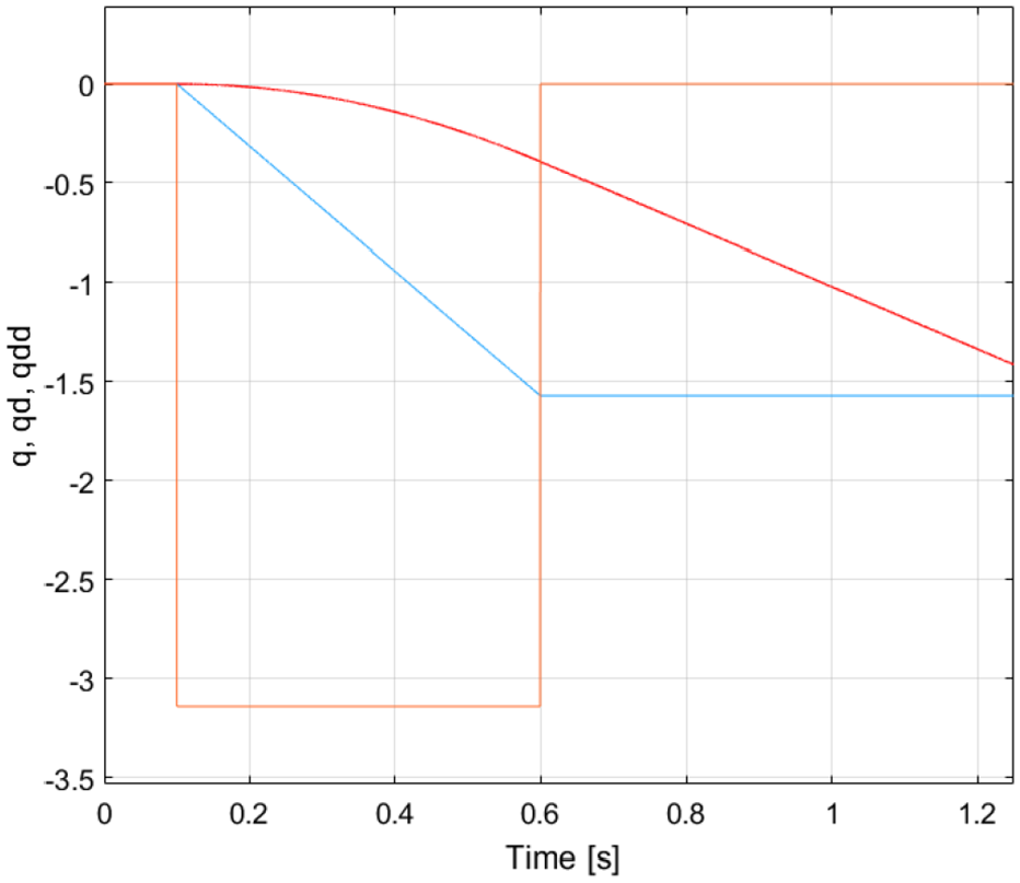
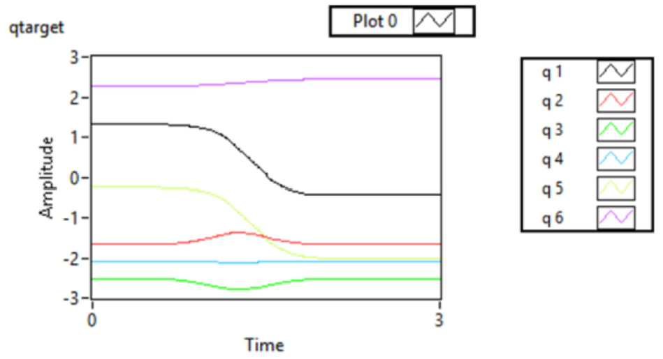
The verification of dynamic parameters was done by measurement. A path similar to the simulation was generated for the measurement. The objective was to move the zero joint position coordinates to the position (–π/2) uniformly for all joints. The control system generated the progress in time of position derivations (Figure 7), which was moderately different from the simulated progress –Figure 8 (see comparison with Figure 5).

Test path and its derivations generated by the control system of the UR5 robot: (a) progress of intended joint position (qtarget), (b) progress of intended joint velocity (qdtarget), and (c) progress of intended joint acceleration (qddtarget).

Desired moments of individual joints when moving along the test trajectory according to Figure 7. (a) Measured moment 1st joint, (b) measured moment 2nd joint, (c) measured moment 3rd joint, (d) measured moment 4th joint, (e) Measured moment 5th joint, and (f) measured moment 6th joint.
The progresses of torques measured on individual joints are shown in Figure 5. The differences point to imprecision of the dynamic model in Matlab, which subsequently had to be adjusted to perform the measurement. The required moments of the individual joints are shown in Figure 8.
Conditions for the conducting of the tests
The robot must be mounted in line with the manufacturer’s recommendations. The robot must be completely assembled and fully functional. All necessary balancing activities, aligning procedures and functional tests must be done in a suitable way. Before the test, the robot’s movements must be limited as necessary for the adjustment of the measuring instruments. The test must be preceded by a warm-up operation, as it is specified by the manufacturer. If the robot has user-adjustment possibilities, that may influence any of the tested characteristics, such a condition used during the test must be specified in the test protocol and must be observed during each test in an unchanged state. 17
The temperature of the ambient environment during the tests Θ°C is (20 ± 2)°C, in line with the standard, or Θ°C should be in the range between 5°C and 40°C. Since the measurement took place in the premises that were not air-conditioned, it was not possible to secure the temperature (20 ± 2)°C, the test was conducted in the allowed temperature range specified by the manufacturer of the UR5: (Θ°C [0–50]°C), specifically (Θ°C [17–22]°C).
The measured placement and orientation data (coordinates xj, yj, zj, aj, bj, cj) must be expressed in a coordinate system whose axes are perpendicular with the axes of the coordinate system of the base.
The measurement point must lie at such a distance from the mechanical interface as it is specified by the manufacturer. The location of that point in the coordinate system of the mechanical interface must be recorded (Figure 9):
Coordinates of the measurement point (measurement cube – MC) – (XMC: +150 mm, YMK: 0 mm, ZMK: 0 mm).
Coordinates of the measurement point (measurement ball – MB) – (XMB: +85 mm, YMG: 0 mm, ZMG: 0 mm).

Coordinates of the measurement point.
All tests must be done under the conditions of 100% rated payload (mass, location of the centre of gravity, moment of inertia) in line with the specification (technical conditions) of the manufacturer.
In order to be able to characterize robots from the point of view of the dependence of their operational characteristics on the load, additional optional tests with the rated load mass reduced to 50% may be made (Table 3). The location of the centre of gravity of the used rated test loads must be the same during all tests.
Test loads.

All pose characteristics must be tested at the maximum velocity achieved between the prescribed positions: that means the speed of movement is set at 100% in each case. Additional tests may be made at 50% and/or 10% values of this speed. For the path characteristics, tests at 100%, 50% and 10% of the rated path velocity must be made, as it is specified by the manufacturer for each of the tested characteristics (Table 4). The prescribed velocity must be such that the robot is able to achieve that velocity along at least 50% of the test path.
Test speeds for pose characteristics.

The minimum number of cycles that must be done when each characteristic is tested for unidirectional pose accuracy and pose repeatability 30 cycles.
Measurement conditions
The tests were carried out in the premises of the workplace, whose working environment is characterized by the ambient temperature, relative humidity and atmospheric pressure.
Specific ambient parameter values at which the tests were carried out are contained in individual partial protocols.
Electric power supply parameters:
supply voltage of the electric grid: 230 V ± 2%
frequency of the electric grid: 50 Hz ± 2%
The measurements were done on an UR5 industrial robot with the relevant control system.
The loading of the mechanical interface flange was simulated by a load weighing 5 kg.
The operational speeds during the tests were set at the values prescribed in the methodological sheet of the specific test and they are contained in the respective partial protocols.
The measured points in the measurement plane of the measurement cube are set in line with the standard, 1 Figure 8.
The placement of the measurement cube in the robot’s workspace was done in line with the standard, 1 Figure 9.
The test cycle for individual tests was determined in line with the prescription in the standard. 1 The measurement cycles are contained in the partial protocols of specific tests.
The positioning of the measurement ball in the robot’s workspace was done in line with the standard. 1
Positioning of the cube in the workspace
A simple cube (Figure 10) whose vertices are marked from C1 to C8, is placed in the workspace (Figure 12), while the following requirements must be met:
- the cube must be placed in the part of the workspace where the most frequent use of the robot is expected;
- the cube must have the maximum allowable volume with edges parallel to the coordinate system of the base.

Measurement cube, measurement plane, measurement points.

Demonstration of robot measuring cycles.

Placement of the measurement cube in the robot’s workspace.
P1 is the intersection of the diagonals and is the centre of the cube. Points P2 through P5 are distant from the ends of the diagonals by (10 ± 2)% of the diagonal length. During the movement between all test positions, all joints of the robot must be applied. The robot arrives at the position of point P1 and then continues through point P4 until it returns to the initial point P1. The movement between individual positions is unidirectional and done at specified velocities. The measurement runs until the robot attains the pose of the end point (end pose).
For the implementation and evaluation of individual tests, methodological sheets were created, describing the basic properties and test parameters.
Measuring means
For the verification of the parameters of the UR5 robot, measuring means specified in Table 5 were used. The measuring nest with internal dimension 90 × 90 × 90 mm3 (item 17), measuring cube with 60 × 60 × 60 mm3 diameter (item 18), and measuring ball with Ø 60 mm diameter (item 19) were made on order by the company. The assembly of the measuring nest and its positioning during measurement is shown in Figure 13.
List of measuring means used.

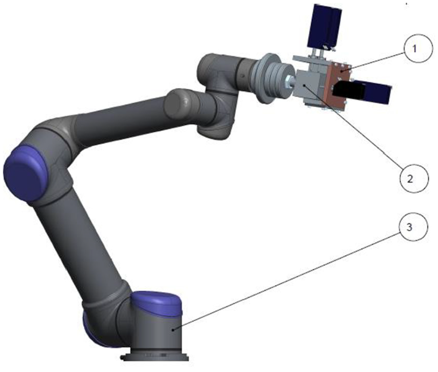
Placement of the measuring cube in the robot’s workspace (1. Measuring nest, 2. Measuring tip, 3. Robot UR5).
During the measurement, the measuring cube was placed on the robot’s arm. It, by means of a program, was repeatedly positioned into the measuring nest. Upon the completion of the movement, linear incremental path sensors were activated by means of a pneumatic jig and deviations were measured. They were recorded on evaluation equipment. Pose values from the robot’s server, obtained by means of a program in the LabView environment, were also archived.
Implementation and evaluation of measurements of unidirectional pose accuracy (AP) of the UR5 robot
The object of the measurement of unidirectional pose accuracy (AP) was the arm of the collaborative robot UR5 from the company Universal. Three types of measurements with a detailed assessment of the robot and with the processing of 60 measurement sets were made. Out of those 60 measurement sets, three measurement sets, each containing 30 measurement samples, were selected and subsequently processed. The first measurement was made at the robot’s 100% load and adjusted 10% speed of movement. The second measurement was made at the robot’s 100% load and its 50% speed. And the last – third – measurement was made at the robot’s 100% load and 100% speed.
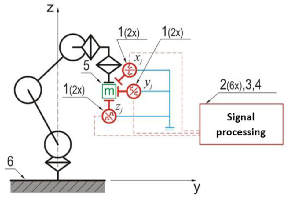
The purpose of the measurement was to determine the deviation between the programmed and attained positions of the robot’s end member in its repeated move to the program position. The measurement was done in accordance with the provisions of the ISO 9283 standard (Manipulating industrial robots – Performance criteria and related test methods). 1 The measurement was done with the principle of moving the end part of the robot with a mounted measurement cube to the measurement location (measurement nest) and by the reading of measured values from a system of six sensors (Figure 14).18,19

Principal measurement setup.
The measurement was done by the repeating of the test cycle 30 times. In the measurement, the end part of the robot was loaded with a test weight with a mass equal to 50% and 100% of the robot’s rated payload. The speed of the robot’s movements during measurements was set at the value of 10, 50 and 100% of the maximum speed of its movement.
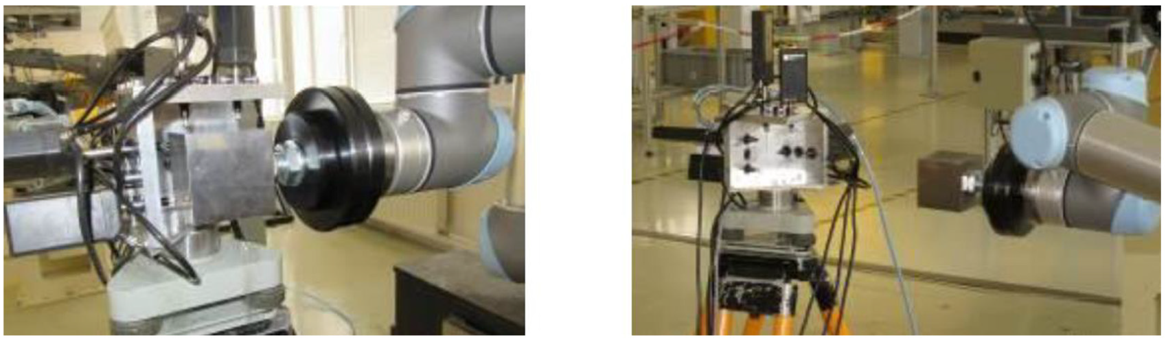
The measurement of the position of the UR5 robot was done by means of six linear incremental sensors (1) Heidenhain MT 25 (MT 12) with six evaluation units (2) Heidenhain VRZ 401. The robot was placed on a solid stand (6). The resulting signal values were processed by means of a computer with installed software (3). Furthermore, a camera (4) was used in the measurement. Moreover, a measurement weight (5) was mounted on the robot’s flange – a weight and a measurement cube – measurement nest. The setup of the measurement of the unidirectional pose accuracy of the UR5 robot is shown in Figure 15.
Setup of the measurement of the unidirectional pose accuracy of the Universal UR5 robot.
Measurement with the robot’s 100% load and 10% speed
The measured values at the robot’s 100% load and 10% movement speed are shown in Table 6. On the basis of the measured values, the robot’s unidirectional pose accuracy and orientation accuracy was calculated and evaluated.
a) The unidirectional pose accuracy was calculated according to the formula:


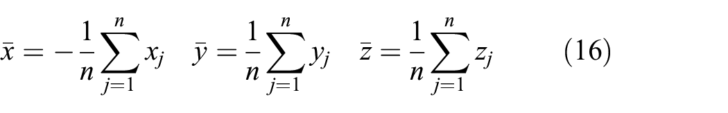
where (xc, yc, zc) are programmed values and (xj, yj, zj) are measured ones. The coordinates of the barycentre of the points attained at n repetitions of the same position are calculated according to the formulae:

b) Unidirectional orientation accuracy:

where

are mean values of angular orientations attained at n repetitions of the same position. (ac, bc a cc) are angles of the programmed position and (aj, bj a cj) are angles of the jth attained position. By comparing the calculated values with the design ones it was found out that the parameter complies on the basis of the calculation:

Measured values at the robot’s 100% load and 10% speed.

Measurement with the robot’s 100% load and50% speed
The measured values at the robot’s 100% load and 50% speed of movement are shown in Table 7. The purpose of the measurement was to establish conformity between the placements and position orientations after n repetitions of the movement into the same programmed pose in the same direction. On the basis of the measured values, the RP value was determined as the radius of the ball with its centre in the barycentre and angular dissipation.
Measured values at the robot’s 100% load and the robot’s 50% speed.

The following was calculated from the measured values:
a)

where (

b)
where (ac, bc a cc) are angles of the programmed position; (aj, bj a cj) are angles of the jth attained position.

By comparing the calculated values with the designed ones, the parameter was evaluated as compliant.
Measurement with the robot’s 100% load and100% speed
The measured values at the robot’s 100% load and 100% speed are shown in Table 8. On the basis of the measured values, the robot’s unidirectional pose accuracy was calculated and evaluated.
a) Unidirectional pose accuracy:


where (xc, yc, zc) are programmed values and (xj, yj, zj) are measured ones. The coordinates of the barycentre of the points attained after n repetitions of the same position are calculated according to the formulae:
b) unidirectional orientation accuracy:

where

are the mean values of the angular orientations attained after n repetitions of the same position. In that, (ac, bc a cc) are angles of the programmed position and (aj, bj a cj) are angles of the jth attained position.


Measured values at the robot’s 100% load and 100% speed.

By comparing the calculated values with the designed ones, the parameter was evaluated as compliant.
Measurement results
The measurement protocols of individual tests contain basic information about measuring means, measured values, evaluations of measured values and evaluations of measurements.
In the tests AP and RP the evaluation of the measurement is done by the comparison of the measured values with the values specified by the manufacturer. The result is declared in the form ‘PARAMETER COMPLIES’ or ‘PARAMETER DOES NOT COMPLY’.
Evaluation of the ‘Unidirectional pose accuracy’(AP) test
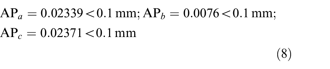
In the (AP) test, 60 measurements at five measurement points (P1, P2, P3, P4, P5) were made in total, with two load combinations (100% and 50%) and three combinations of movement speed (100%, 50% and 10%). Though the standard prescribes the making of 30 measurements, due to increased vibrations of the 5th axis in some working positions, a double number of measurements was made, of which 30 ones in which vibrations did not appear were selected. Overview data of (AP) with the results of calculated values are shown in Table 9.
Calculated values of unidirectional pose accuracy (AP) of the UR5 robot.
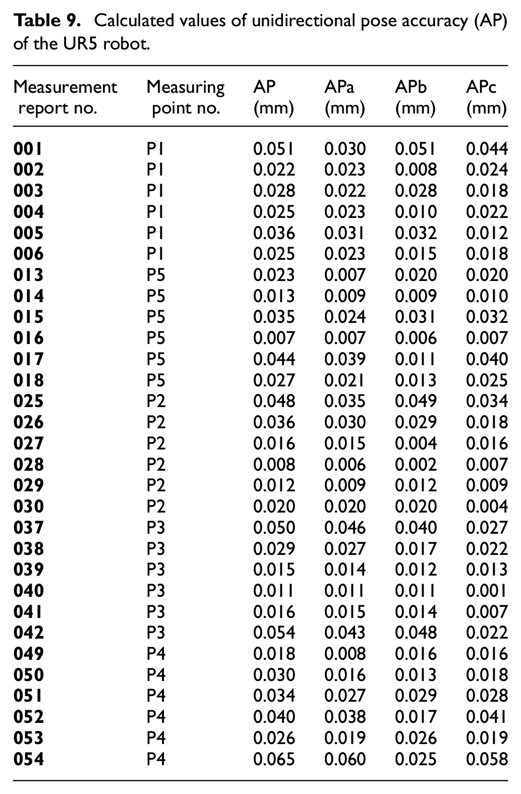
The robot’s manufacturer does not state the value of the unidirectional pose accuracy. In the UR5 robot manufacturer’s catalogue data, only the value of unidirectional pose repeatability (±0.1 [mm]) is specified. For this reason, the unidirectional pose repeatability was selected as the reference one. Since none of the measured values exceeded the prescribed value, we can state that the robot COMPLIES.
The calculation procedure for the unidirectional pose accuracy is derived from the following formulae:


where (xc, yc, zc) are programmed values and (xj, yj, zj) are measured ones. The coordinates of the barycentre of points attained after n-repetitions of the same position are calculated from the formulae:

The output of the calculation of unidirectional orientation accuracy is derived from the formulae:

where

are mean values of orientation angles attained after n-repetitions of the same pose. In that, (ac, bc and cc) are angles of the programmed pose and (aj, bj and cj) are angles of the j-th attained pose.
Figure 16 shows an informative progress of calculated values of unidirectional pose accuracy (AP) in three mutually perpendicular directions at two load values, three speed values, and five measurement points. Since data calculated under different conditions are compared (loads, speeds and spatial positions), this diagram has only an informative function.

Unidirectional pose accuracy (AP) of the UR5 robot.
Figure 17 shows an informative progress of calculated values of unidirectional pose accuracy (APa, APb and APc) in two mutually perpendicular directions at two load values, three speed values, and five measurement points. Since data calculated at different conditions (loads, speed and spatial positions) are mutually compared, this diagram has only an informative function.

Unidirectional pose accuracy (APa, APb, APc) of the UR5 robot.
Evaluation of the ‘unidirectional pose repeatability’ (RP) test
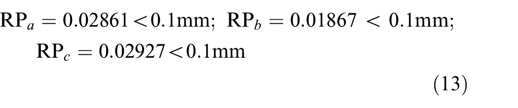
In the (RP) test, 30 measurements at five measurement points (P1, P2, P3, P4, P5) were made in total with two loading conditions (100% and 50%) and three combinations of the movement speed (100%, 50% and 10%). The overview data of the (RP) with the resulting calculated values are shown in Table 10.
Calculated values of unidirectional pose repeatability (RP) of the UR5 robot.

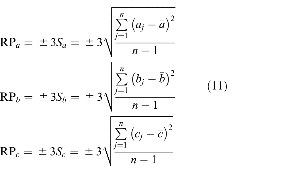
The unidirectional pose repeatability calculation procedure is derived from the formulae:


where (xj, yj, zj) are the real (measured) values. The barycentre coordinates of the attained points after n repetitions of the same position are calculated according to the formulae:


where (ac, bc and cc) are angles of the programmed pose; (aj, bj and cj) are angles of the jth attained pose.
After adding the values to the formulas for measuring the measuring point P1 to P5 at individual loads and speeds and their subsequent processing, we obtain the results shown in Table 10. Table 11 shows the measured values for measuring point P1 at a robot load of 50% and a robot speed of 10%.
Example of measured values for measuring point P1 at robot load 50% and robot speed 10%.

By adding the measured values of the formulas we obtain the results:


The arrangement of the measuring workplace in the measurement of the unidirectional pose accuracy and repeatability (AP, RP) are shown in Figure 18, where the measurement at points P4 and P3 by means of a system of six sensors is shown.
Measurement of the AP at points P4 and P3.
In the catalogue data of the UR5 robot’s manufacturer, a unidirectional pose repeatability value (±0.1 [mm]) is specified. Since none of the measured values exceeded the prescribed value, we can state that the robot
Figure 19 shows an informative progress of the calculated values of the unidirectional pose repeatability (RP) in three mutually perpendicular directions at two load values, three speed values and five measurement points. Since calculated data under different conditions are mutually compared (loads, speeds and spatial positions), this diagram has only an informative function.

Unidirectional pose repeatability (RP) of the UR5 robot.
Figure 20 shows an informative progress of the calculated values of unidirectional pose repeatability (RPa, RPb a RPc) in two mutually perpendicular directions with two load values, three speed values and five measurement points. Since calculated data under different conditions are mutually compared (loads, speeds and spatial positions), this diagram has only an informative function.

Unidirectional pose repeatability (RPa, RPb, RPc) of the UR5 robot.
Evaluation of the quality of the control of the robot’s individual axes’ drives
During the measurement of repeated accuracy, data about the condition of the robot for the needs of additional analysis of the occurred inaccuracy were recorded. This model evaluation took place under the full load of 5 kg and the robot’s full speed, 100%, in the measurement from the measurement point P5 to P4 (Figure 21). In one of the least favourable measurements for the determination of the quality of control (in particular during movement), we compared the measured values with the reference ones. The results are shown in Figure 20.
Measurement path in joint coordinates.
Figure 22 shows that the current in particular shows a large control deviation. The current in this case is proportional to the drive torque, from which the imprecision of the calculation of the dynamic model in the robot’s control system results. The controller then had to compensate this imprecision. The controller, probably due to the high load near limit load values of the effector, did not work correctly and introduced noise and perceivable vibrations into the system. In the case of the UR5 robot, neither the parameters of the controllers, nor the control structure can be changed by the user, therefore this phenomenon could not be eliminated.

Measured control deviations during movement: (a) position deviation (dq), (b) velocity deviation, (c) current deviation (dI), and (d) effector position deviation (dTCP).
All calculated values are smaller than the designed parameter of the robot specified by the manufacturer in its operational characteristics RP, including the calculated measurement imprecisions due to the distance of individual points from the measurement system. On the basis of the measurement, the unidirectional pose repeatability of the UR5 robot has been proved to meet the technical specification provided by the manufacturer.
Conclusion
The article describes the results of the measurement and evaluates in detail the achieved pose accuracy of the UR5 robot. The carried-out measurement was based on an imaginary ISO cube, placed in the robot’s most used workspace. Before the measurement itself, a test plan of measurements and a list of purchased measurement components according to the requirements of the standard was created. The pose measurement of the UR5 robot was done in line with the ISO 9283 standard. In the measurement, six linear incremental sensors Heidenhain MT 25 (MT 12) with six evaluation units Heidenhain VRZ 401 were used in the presence of a camera and the measurement results were subsequently processed in the appropriate software. The measurement took place in three cases where the end part of the robot was loaded with a test load with a mass equal to 50 and 100% of the robot’s rated payload, at the speed of the robot’s movements set at 10, 50 and 100% of the maximum speed of its movement. As part of the measurement, 60 measurement sets were processed, while each set contained another 30 measurements. The article describes selected measurement sets, which were processed in the form of tables and graphs based on calculations. Based on the obtained results of the measurements of the robot’s unidirectional pose accuracy and unidirectional pose repeatability, it is possible to state that the robot’s repeatability in the observed workspace is identical with the repeatability specified by the manufacturer.
Footnotes
Acknowledgements
This article was created thanks to the framework of the project VEGA no. 1/0026/19 and APVV-16-0355.
Handling Editor: James Baldwin
Declaration of conflicting interests
The author(s) declared no potential conflicts of interest with respect to the research, authorship, and/or publication of this article.
Funding
The author(s) received no financial support for the research, authorship, and/or publication of this article.