
Abstract
Generally, pressure oscillation has negative effect on hydraulic crane system which requires high dynamic stability under a flexible operating condition. In order to reduce the hydraulic pressure oscillation, a self-tuning fuzzy proportional–integral–derivative control strategy is proposed for improving the control performance of hydraulic crane. In this article, a fuzzy proportional–integral–derivative controller which consists of a proportional–integral–derivative controller and a fuzzy inference unit with two inputs and three outputs is designed for valve control. Both fuzzy proportional–integral–derivative control and traditional proportional–integral–derivative control are simulated using MATLAB based on the model of hydraulic crane. Simulation experiments are conducted with different crane tip velocities. The experimental results show that pressure amplitude reduced about 25% at low velocity and pressure oscillation of hydraulic cylinder is suppressed comparing with traditional proportional–integral–derivative controller. In addition, fuzzy proportional–integral–derivative control enables a smoother variation and a higher accuracy in changing processes of joint angle and crane tip position. The performance of the hydraulic crane is improved.
Keywords
Introduction
With advancement of industrialization, different types of hydraulic machines have been utilized in many aspects such as automobile industry, forestry, and aerospace industry. 1 Hydraulic components are quieter than pneumatic ones and hydraulic drives are much stiffer compared to electric drives. 2 Therefore, due to high durability and the ability to produce large forces at high speed, hydraulic cranes that can be seen a kind of hydraulic manipulator have also been used in a wide range. Coupled with the rapid development and increased competition worldwide, the development of hydraulic cranes tends to be safer, higher reliability, and more effective. 3 Meanwhile, the structures become larger and heavier than before. Nevertheless, due to their flexible work conditions, high operating pressure, and speed, most of them require higher dynamic performance to ensure the high-quality system. 4 Especially, hydraulic cranes work as lifting machines which are used in applications operating under high pressure and demanding control accuracy. Control methods have always been a significant issue in the development process. There are many works that concentrate on control algorithms for improving the system performance.
The nonlinear dynamic characteristics of hydraulic system which have impact on stability and accuracy are difficult to control. 1 In order to deal with parameter uncertainties and nonlinearities of hydraulic system, Lyapunov theory is used to evaluate the stability of control system5,6 and nonlinear tracking control methods are proposed based on Lyapunov function.1,7,8 Adaptive control methods based on intelligent control theory are also discussed in the literatures. For example, Knohl and Unbehauen 9 applied artificial neutral networks to adaptive position control of electrohydraulic servo systems. While taking account of the nonlinearities of the system, Wonohadidjojo et al. 10 proposed a method to control the position of electrohydraulic system by employing the fuzzy logic controller that optimized parameters based on particle swarm optimization.
Among several control methods, conventional control methods such as proportional–derivative (PD) and proportional–integral–derivative (PID) are widely used in industry process control due to its simplicity of operation and accurate position control.4,11 Nevertheless, these control methods cannot satisfy the nonlinearities of hydraulic system sufficiently and most of the systems suffered from chattering due to linear characteristics.4,10,12 In this situation, many studies focus on control strategies that combining PID controller with fuzzy control theory that are based on expert experience and can control object effectively. Thus, they can make up each other and take full advantage. For instance, Cetin developed a hybrid fuzzy PID controller that combined nonlinearity of fuzzy control and accuracy of traditional PID control. In accordance with the target position of piston, the two control methods can be switched. 4 Wan et al. 13 proposed a dynamic adaptive control method that was based on the least squares support vector machine and the genetic algorithm to adjust nonlinear system and optimize the control law. Dehghani and Khodadadi 14 used fuzzy logic self-tuning PID controller for controlling the flexible joint robots. Ghosh et al. 15 designed a self-tuning fuzzy PID with bias controller for 2-degree-of-freedom (DOF) electrohydraulic parallel manipulator and analyzed the real-time performance.
The literature studies mentioned above only concentrate on how to cope with system nonlinearities and achieve accurate control performance. Pressure oscillation also has adverse effect on the performance of hydraulic crane. Unstable chamber pressures of cylinders can lead to jitter of valve spool and the flow fluctuation of control valve can aggravate crane boom vibration which will reduce positioning accuracy and efficiency of hydraulic crane. 16 In addition, low-frequency boom vibrations are very harmful to operator. 17
Several control methods have been proposed to deal with the oscillation in hydraulic manipulators. Moon 17 proposed an input shaping control scheme which can generate an opposite phase input to eliminate the vibration of boom manipulator. Based on the relation between natural frequencies and dynamics of manipulator, Kovanen and Handroos proposed a control method that calculated the lowest frequency of crane and filtered the higher frequencies by piston positions and mass loads. Simulation results showed that vibration amplitudes were reduced with the proposed adaptive control function. 18 La Hera et al. 19 designed a cascade controller that was used to control hydraulic torque and reduce oscillations. There were two stages of the cascade control: the outer loop controller computed the reference torque and the inner loop controller calculated the valve input based on the reference torque. Yang proposed an improved proportional–integral (PI) control algorithm that combined fuzzy set-point weighting with the PI controller to reduce the low-frequency hydraulic–mechanical oscillations. 11
When focus on these studies, both control accuracy and pressure oscillation are important issues for hydraulic crane. Therefore, a control method which concentrates on both two aspects is required. In this article, a self-tuning fuzzy PID control method is developed not only to reduce pressure oscillation, but also to improve the performance of hydraulic crane system. According to angular position feedback, the parameters of PID controller can be adjusted adaptively based on fuzzy rules. The valve spool is determined by output of controller. Simulation experiments are conducted to verify the effectiveness of the proposed control method. The advantage of the method can be easily observed by comparing with traditional PID control.
Description of hydraulic crane model
In this study, the proposed fuzzy PID control is implemented on the hydraulic crane model which is established by Heinze. 12 The hydraulic crane operates based on two important parts: mechanical model and hydraulic system. The required joint variables that correspond to target crane tip position are calculated using inverse kinematics. The valve package distributes the fluid in terms of output of controller. The movement of each cylinder is driven by pressurized fluid separately, and the hydraulic force acts on the links which are attached to piston rods. The sensors that can obtain feedback information are equipped on the crane in order to implement feedback control. Consequently, the crane tip moves to its target position. The crane’s model and the placement of sensors are shown in Figure 1. Model of crane is presented in detail in the literature 12 and is only briefly described here.

Hydraulic crane system.
Mechanical model
In this article, axial rotation around first link will not be considered, and the crane only moves in two-dimensional plane. Accordingly, the crane framework consists of four links (three beams and a telescope beam) and three joints (two revolute joints and one prismatic joint). The fourth link slides inside of the third link which is a prismatic joint. These joints are connected to three double acting cylinders separately.
The number of joint variables is determined by the DOF of the system. There are two rotary joints and one prismatic joint according to the model, and the generalized coordinates are built up as follows

where α is the angle of joint 1, β is the angle of joint 2, and x is the extension of third cylinder. The vector of generalized coordinate
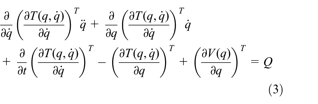
The dynamic approach based on Euler–Lagrange method is used to describe the motion of mechanical structure with geometric constraints. In terms of total kinetic and potential energy of the system, the Euler–Lagrange equations can be expressed as follows

where Q is the vector of generalized forces associated with q, T is the total kinetic energy, and V is the total potential energy of the system.
V(q) is the total potential energy which is a function of the generalized coordinate q only, so it can be obtained that
By defining the mass matrix
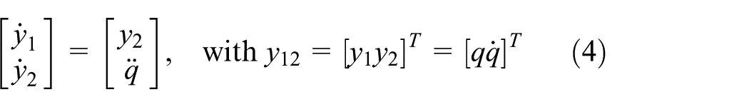
Then, the state space set of the mechanical system can be represented as follows
Hydraulic model
In this study, the hydraulic system will be modeled in two main parts: the valve and the cylinder. The hydraulic system operates by controlling the three-position four-way valve whose spool position is only determined by control input. The pump that is connected to valves delivers constant pressurized fluid to both chambers in cylinders, respectively. Then, pressure of oil forces the piston to move backward or forward.
Referring to above illustration, we can obtain the state space by defining the state vector

where
The state vector of the cylinder hydraulics can be formulated as
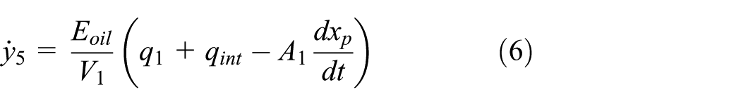

where
Design of fuzzy PID controller
In this article, the movement of the crane is controlled by set speed in two-dimensional plane. In accordance with the literature, 12 conventional PID control could meet the basic operation requirement of the system. However, due to limitation of PID control in this complex system, there are pressure oscillation and position deviation when crane lifts in the vertical direction. Therefore, we applied fuzzy PID control to the first joint of the crane which has the most significant impact on the vertical direction.
Structure of fuzzy PID controller
By integrating fuzzy control into the PID controller, fuzzy self-tuning PID controller takes error (marked as e) and change rate of error (marked as ec) as input and tunes its parameters adaptively in order to meet different requirements of control parameter when e and ec change. The structure of fuzzy tuning PID controller of the hydraulic crane system is shown in Figure 2. By detecting e and ec constantly during the operation of control system, the parameters of PID are modified in real time based on the fuzzy control rules so that the good dynamic and static performance can be achieved.
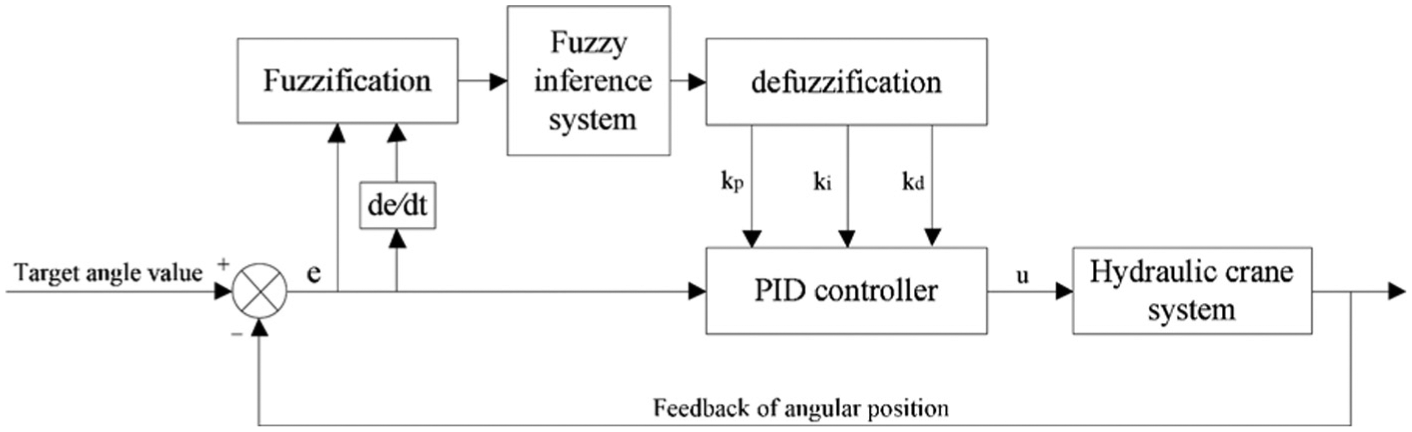
Structure of self-tuning fuzzy PID controller.
There are two inputs and three outputs of the fuzzy inference system. In a sampling period, the inputs are the deviation between measured joint angle and the target angle value e and the change of error ec. The outputs are correction coefficients
Then, the parameters of the PID controller can be obtained from equation (8)

In accordance with incremental PID control algorithm, the PID control expression can be written as shown in equation (9). Here, by substituting the corrected PID parameters into equation (9), we can achieve the output of controller which controls the spool of valve

Definition of domain and membership
All of the input and output variables have to be transformed according to fuzzy subsets. The fuzzy subsets of each variable are the same and defined as follows: {NB (negative big), NM (negative middle), NS (negative small), ZO (zero), PS (positive small), PM (positive middle), PB (positive big)}. The domain of e is {−3,3}, of ec is {−3,3}, of
Then, we have to determine membership functions of fuzzy language variables which provide basis of conversion between fuzzy sets and exact values. S-shaped membership function, triangular membership function, and Z-shaped membership function are employed to fuzzy system in this study. The membership functions of input variables and output variables are shown in Figures 3 and 4, respectively.

Membership of input variables: (a) membership functions of e and (b) membership functions of ec.

Membership of output variables: (a) membership functions of
Design of fuzzy control rules
There are 49 fuzzy rules and these rules are described in Table 1. By establishing fuzzy control regulation table based on technical knowledge and experience of experts, we can achieve the fuzzy control table which is used to tune three parameters of PID separately.
Fuzzy control rules.

NB: negative big; NM: negative middle; NS: negative small; ZO: zero; PS: positive small; PM: positive middle; PB: positive big.
Defuzzification
After fuzzy inference, the aggregate output fuzzy sets which encompass a range of output values are obtained. In order to resolve output values from the sets, we adopt centroid method which is commonly used for defuzzification. In this method, the centroid of area under the membership function curve is taken as final output of fuzzy inference. Thus, the exact value of
Simulation results and analysis
Based on hydraulic crane model that is described in section “Description of hydraulic crane model,” both of controller design and control simulation are implemented in MATLAB. In order to evaluate the performance of the system with the proposed fuzzy control method, simulation experiments are conducted with different input velocities. The performance is likely influenced by weight load in vertical direction when crane lifts objects. We only changed the vertical velocity of crane tip while the velocity in horizontal direction was set to zero. For comparing with traditional PID control method, the system parameters used for simulation studies of the hydraulic crane are the same as the literature. 12 We run the simulation for 5 s, the initial generalized coordinates (α, β, x) was set to (100,100,0).
Several groups of test were conducted with the crane tip vertical velocities in a range from 0.1 to 0.5 m/s and the velocity was constant in a single test. Two groups of result that can represent the results with other velocities were presented here. The target vertical velocity of 0.2 m/s can be considered a low velocity and 0.45 m/s is higher one. In accordance with kinematic inverse, the target values of α and β are shown in Table 2.
Target value of joint angle.

Figure 5 depicts the variations of α and β with fuzzy PID control and PID control. From Figure 5(b), α did not reach the target value at higher velocity with both of the control methods. As mentioned in section “Description of hydraulic crane model,” the pump is connected to the valves and supplies the valve a constant pressure. The chamber pressures depend on supply pressure of pump and spool position of valve. The control input is restricted to a preset range in accordance with limit of hydraulic unit. From Figure 6, when the control inputs reach the limit, valves operate with maximum spool stroke and chamber pressures are limited. Due to these restrictions of hydraulic parts, the increasing angular velocity of α is limited. Therefore, α cannot reach the desired value at higher velocity. Nevertheless, from Figure 5(a), it could be seen that α is very close to its target value at 0.2 m/s with fuzzy PID control. And based on several experiments, we find that alpha can reach the target value if the velocity is small enough with fuzzy PID control but not the conventional PID control.

Comparison of joint angular variation: (a) angular variation of alpha at vertical velocity of 0.2 m/s, (b) angular variation of alpha at vertical velocity of 0.45 m/s, (c) angular variation of beta at vertical velocity of 0.2 m/s and (d) angular variation of beta at vertical velocity of 0.45 m/s.

Comparison of pressure in both chambers of cylinder 1: (a) pressure of head end chamber of cylinder 1 at vertical velocity of 0.2 m/s, (b) pressure of head end chamber of cylinder 1 at vertical velocity of 0.45 m/s, (c) pressure of rod end chamber of cylinder 1 at vertical velocity of 0.2 m/s and (d) pressure of rod end chamber of cylinder 1 at vertical velocity of 0.45 m/s.
From Figure 5(c) and (d), β can achieve the target value; however, it can be seen clearly that there was vibration before achieving the target angle in conventional PID method while fuzzy PID control provided a smoother changing process. Combining with Figure 7, the pressure oscillations in chambers during the crane operation are directly reflected in the variation of joint angle. As mentioned before, the pressures in cylinder chambers are changed by the valve and the hydraulic cylinders operate by force differences between two chambers. Furthermore, the position of main valve spool is only controlled by control input. That is to say, changing process of pressure is influenced by control input greatly. In fuzzy PID method, PID parameters can be adjusted in real time so the dynamic changing process of pressure and joint angle is more stable.

Comparison of pressure in both chambers of cylinder 2: (a) pressure of head end chamber of cylinder 2 at vertical velocity of 0.2 m/s, (b) pressure of head end chamber of cylinder 2 at vertical velocity of 0.45 m/s, (c) pressure of rod end chamber of cylinder 2 at vertical velocity of 0.2 m/s and (d) pressure of rod end chamber of cylinder 2 at vertical velocity of 0.45 m/s.
Comparisons of chamber pressures of cylinder 2 are depicted in Figure 7. The higher the velocity was, the higher the cylinder pressure was. As it can be calculated from Figure 7(a) and (c), we could obtain the decreasing percentage of pressure amplitude by the formula
Comparison of pressure amplitudes in both chambers of cylinder 2.

PID: proportional–integral–derivative.
Figure 8 shows the curves of crane tip position in vertical and horizontal direction at different target velocities. As mentioned before, the joint angle did not reach the target value, so the deviation can also be observed in crane tip position curves. From Figure 8(a), the deviation in horizontal direction can be corrected at a low target velocity. It can be computed from Figure 8(c), the average vertical velocity with fuzzy PID control was 0.18 m/s which was very close to the target value of 0.2 m/s, while it was only 0.12 m/s with PID control. Although at a high target velocity, two control methods presented a similar performance; the advantage of the proposed method still can be observed. From Figure 8(b), compared with PID control method, it took shorter time that horizontal velocity trends to be zero with fuzzy PID method. And the variation process of crane tip was smooth. In Figure 8(d), PID control shows worse linearity which implies velocity fluctuation of crane tip in vertical direction.

Comparisons of crane tip position with two control methods: (a) position of crane tip in horizontal direction at vertical velocity of 0.2 m/s, (b) position of crane tip in horizontal direction at vertical velocity of 0.45 m/s, (c) position of crane tip in vertical direction at vertical velocity of 0.2 m/s and (d) position of crane tip in vertical direction at vertical velocity of 0.45 m/s.
Conclusion
A self-tuning fuzzy PID control method is presented by combining fuzzy control with PID controller for suppressing pressure oscillation and improving the performance of hydraulic crane system. Many groups of simulation experiment are conducted with fuzzy PID control and conventional PID control. By comparing system performances of the two methods at different target velocities, the effectiveness of the proposed method was verified. The comparison results show that fuzzy PID control provides a better performance, because it tunes parameter adaptively based on fuzzy rules which are more effective for flexible system. The target angle can be achieved faster with less vibration with fuzzy PID control. Meanwhile, the comparison of crane tip position further demonstrates the effectiveness of proposed control method. Consequently, the proposed fuzzy PID control method shows great advantage in suppression of vibration and can be well applied to hydraulic crane system.
Footnotes
Academic Editor: Muhammad Akhtar
Declaration of conflicting interests
The author(s) declared no potential conflicts of interest with respect to the research, authorship, and/or publication of this article.
Funding
The author(s) disclosed receipt of the following financial support for the research, authorship, and/or publication of this article: This work was supported by the Fundamental Research Funds for the Central Universities (Grant No. TD2013-4) and Beijing municipal construction project special fund. The authors wish to thank Prof. Dr Peter Wolfsteiner and Alexander Heinze for providing support for this research.