
Abstract
The static metal sealing mechanism is essential for the structural design of subsea pipeline mechanical connector. By analyzing the sealing mechanism and contact pressure on sealing face, the critical condition of the seal is obtained. Based on the superposition theorem of elasticity, the formula of critical mean contact pressure ensuring seal is deduced. The finite element analysis result of critical mean contact pressure agrees with the analysis result very well and the critical mean contact pressure decreases with the increase in pipeline wall thickness and sealing width; however, the radius of pipeline has less influence on it. The critical mean contact pressure of 8-in subsea pipeline mechanical connector is 223.34 MPa and subsea pipeline mechanical connector is designed with ANSYS. The internal pressure experiments indicate that the sealing performance of final designed subsea pipeline mechanical connectors is higher than the design pressure of 4.5 MPa and all the initial designed ones cannot seal up to 4.5 MPa. By observing the sealing indentation on pipeline surface, when the mean contact pressure is higher than the critical mean contact pressure and the contact pressure variance is smaller, a full contact is seen to form a seal. Finally, the vibration experiments prove that the number of vibration is more than 107 and final designed subsea pipeline mechanical connector meets the experiment specification.
Keywords
Introduction
Because of the rapid growth of offshore oil and gas exploitation, more and more pipelines are applied to deep seabed to transport oil and gas, 1 and the operation will increase in pipeline laying, merger, and maintenance. 2 However, how to accomplish mechanical connections between pipelines reliably as well as the related equipment is the key problem to build a subsea oil and gas production system successfully. 3
For various operation depths and connection requirements, corporations in the Unites States, such as Oil state, Cameron, FMC technologies, Quality Connector Systems, and Oceaneering, have developed a series of mechanical connectors. Two typical connectors are well known in the industry. One is used for the flange-end pipelines and the other is for non-flange pipelines. The first type of the connectors includes common flange connector, articulated clamp connector, 4 and collet connector, 5 which are mainly used for connection in pipeline laying and merging. The installation of the connectors is achieved by a special tool, and the sealing principle of the connectors is to squeeze the gasket between the flange ends by the axial clamping force. The other type of connectors is applied in the connection of pipeline without flange. A flange can be fitted at the end of the pipeline by mechanical connection or using double-grip mechanical connectors, such as hydraulic double-grip and seal connector, 6 smart flange, 7 and pipeline connector for connecting a branch pipe to a carrier pipe, 8 which are also used for destructed pipeline renewal. During the connecting operation, destructed pipeline is cut off by the subsea cutting machinery, replaced by an intact pipeline prefabricated on board, and connected together by the mechanical connectors. The complicated design of the conventional subsea mechanical connectors results in inefficient operation, and particularly most of the bolts have to be preloaded. Then, a simple mechanical connector is designed for the connection of water supply and drainage pipelines under low or zero pressure on land. 9 On the basis of this connector design, Haelok Inc. in Switzerland supplies the connectors connecting pipeline less than 168.3 mm in diameter. To make this kind of connector work well in complicated subsea environment, this article presents an improved design, the subsea pipeline mechanical connector (SPMC), that can be used for a larger diameter and a higher internal pressure.
The seal of SPMC is a static metal seal without a gasket, which is the key technique to realize static metal sealing in the connector. The static metal seal is extensively applied in subsea non-weld connections to prevent the leakage of the transportation medium, because of its advantages in condition with high pressure, corrosion, and complicated external forces. 10 In the design of a mechanical connector with a gasket, the gasket factor and minimum gasket seating stress must be determined by the design codes11,12 according to the internal pressure and structural geometry, but these codes are based on a series of assumptions and hence may not calculate the contact pressure and its distribution between flange ends and metal gasket.13,14 ASME Boiler and Pressure Vessel Code (BPVC) Special Working Group-Bolted Flanged Joints (SWG-BFJ) 15 improved the design method of conventional bolted flange joints with gasket, and new gasket constants were defined. However, all conclusions were obtained by the assumption that the contact pressure was uniform on the sealing surface. Sawa et al. 16 had made a research in which the distribution of contact stress which governs the sealing performance is analyzed as a three-body contact problem, using an axisymmetric three-dimensional (3D) theory of elasticity. This work was further simplified by treating the pipe flange and the gasket as hollow cylinders. The formula of gasket contact stress and its variation through the gasket width was deduced on the basis of nonlinear characteristic of the gasket materials, 17 which was supported by the experiment and finite element analysis (FEA). Nonetheless, this method only predicted that flange rotation had effects on sealing performance. In addition, finite element method was applied to research the distribution of the contact pressure on the sealing surface.18,19 Their work considered the influence of nonlinear characteristic of gasket and internal pressure; however, the analysis was based on the spiral wound gasket. Our previous article 20 proved that the mean contact pressure and its distribution on sealing surface had an important effect on static metal seal. However, no relevant public research has been done on sealing mechanism of the mechanical connector without a gasket.
In order to obtain reliable sealing performance of SPMC, we analyzed the sealing mechanism of static metal sealing without a gasket and established the critical condition of the seal. Based on the superposition theorem of elasticity, the formula of the critical mean contact pressure is deduced, which can be used to calculate the minimum contact pressure of static metal seal. Meanwhile, the effects of the key structural parameters on the critical mean contact pressure are analyzed. The 8-in SPMC is designed with ANSYS, and the internal pressure experiments, indentation experiments of the sealing face, and vibration experiments are carried out.
Structure and sealing mechanism of SPMC
The structure of SPMC is shown in Figure 1, which is composed of a basic body and two press rings. The external surface of the press ring is a straight cylinder, and the internal surface is a profile that consists of cylindrical and conical surfaces. On the external surfaces of the basic body, two convex rings are produced on each side. The two ends of the basic body are gripper parts. On the internal surface of the basic body, two sealing rings are produced on each side.
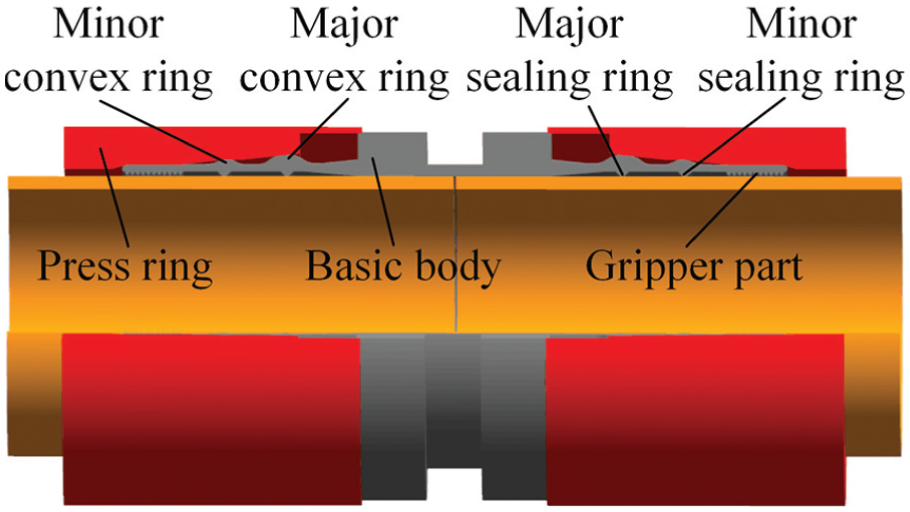
Structure of SPMC.
The installation of SPMC is shown in Figure 2. The press ring is compressed by installation tool and moves toward the middle of basic body along the axial direction. When the press ring moves toward the middle of SPMC, its internal conical surfaces will compress sealing rings and gripper parts to the external surface of the pipeline. The press ring is compressed further, which will increase the contact pressure on the sealing face. When the contact pressure exceeds the critical contact pressure, enough deformation on sealing face will happen, which forms a static metal sealing. Meanwhile, gripper parts are embedded into the external surface of the pipeline and connect the pipelines as a whole piece, which resists the complicated external force, protects sealing face, and improves reliability and lifetime of SPMC in submarine environment. In the installation of SPMC, Remote Operated Vehicle (ROV) can operate other equipments, and operators on board can observe work environment in underwater by ROV.

Installation of SPMC.
Static metal sealing mechanism
The internal surfaces of the sealing rings are not perfect and its roughness is a little better than that of the pipeline, as shown in Figure 3. If the deformation on the sealing face is not enough, two sealing faces will not fully contact each other, which tends to generate the micro leak path, 21 particularly when external forces and internal pressure are applied, as shown in Figure 4. In order to achieve a reliable static metal sealing, the contact pressure on the sealing faces should reach a critical value. The micro leak paths will be blocked by reducing the height of micro-peaks and the depth and diameter of micro-pits or increasing the diameter of micro-peaks, which achieves a reliable static metal sealing. 22 The micro leak paths are formed by linking micro chambers formed by the overlay of micro-peaks and micro-pits on the sealing faces. Because micro-peaks and micro-pits on the sealing surface obey the normal distribution, the increase in the sealing face width will effectively reduce the probability of the micro leak paths generation. The contact pressure and sealing face width are two important parameters in the design of static metal seal.23–25 In order to generate reliable static metal sealing, which will not be affected by the surface roughness, the contact pressure on the sealing face should be more than the Brinell hardness HB of the softest material. 26 Taking the design of Badische Anilin-und-Soda-Fabrik (BASF) lenticular gasket of Germany as a basis, the width of the sealing face is not less than 1/16 in. 27
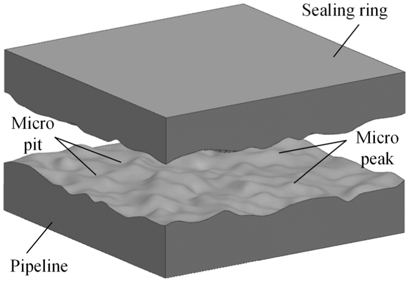
Micro surface.

Micro leak path.
Critical condition of seal
By considering subsea environment, the sealing rings and pipeline should be in elastic deformation and have enough elastic spring-back to resist the negative effects of internal pressure, temperature, and external load for seal. 28 Assuming that the deformation of the sealing part is always kept within the range of elastic deformation range in installation and operation condition. LAD is the width of the sealing face. Because of the intercoordination of elastic deformation between the sealing ring and the pipeline, the contact pressure on the boundary of the sealing face is higher than that of the central plane and the distribution is symmetric about the central plane of the sealing face, as shown in Figure 5. On the basis of static metal sealing mechanism in section “Static metal sealing mechanism,” the critical condition to realize reliable static metal sealing is

where PB is the contact pressure at B, PC is the contact pressure at C, LAB is the distance between A and B, and LCD is the distance between C and D.

Distribution of contact pressure.
In order to realize the static metal sealing,
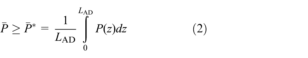
where the contact pressure on the sealing face, P(z), meets the critical condition of equation (1) and
Solution of critical mean contact pressure
The contact pressure on the sealing face includes two parts, that is, the contact pressure from installation and that from the internal pressure. Figure 6 shows the distribution of the internal pressure. The internal and external surfaces of the pipeline are under the internal pressure on the left of “W” line and there is no expansion tendency for the pipeline. However, on the right of W line, the internal pressure is applied on the internal surface only and expansion of the pipeline tends to happen, which increases the contact pressure on the sealing face and improves the sealing performance of SPMC. Based on the above analysis, the SPMC is a self-tight seal. As long as the mean contact pressure from installation is more than the critical mean contact pressure, the SPMCs will maintain their high sealing performance. Therefore, the mean contact pressure from installation is analyzed to design SPMC.

Distribution of internal pressure.
Equivalent model of contact pressure
The static metal seal of SPMC is realized by the squeeze on the sealing surfaces. By the analysis of structural feature and force condition of the pipeline and SPMC, the geometrical profile, constraints, and boundary conditions of pipeline are symmetric about the central line, and the mechanical model of the pipeline is a 3D axial symmetric constitutive model.
The cylindrical coordinate system is established, as shown in Figure 7. z-axis coincides with the central line of the pipeline, r points along the radial direction, θ is along the circumferential direction, and r–θ plane coincides with the low end of band of the contact pressure. In axisymmetric elastic problem, stress, strain, and displacement of pipeline wall only relate to r and z. Because the contact pressure is non-uniform on the sealing face, we use a sectional approximation method to solve the formula of the contact pressure on the sealing face.

Approximate model of contact pressure.
L AD is divided uniformly into n sections, and the width of every section is li = LAD/n = l. If n is big enough, we can assume that the contact pressure pi is uniform with a width of li, and the equivalent mechanical model is n bands with uniform contact pressure pi with a width of li applied on the external surface of the pipeline, where i = 1, 2,…, n.
Under band of uniform contact pressure pi with a width of li, the stress in the pipeline can be solved by superposition method in Figure 8. The stress of the outer radius at z = 0 and z = l1 is pi/2 or pi, which will not affect the distribution of stress in the pipeline, because the area is 0.

Superposition of pressure.
Solution of pressure band with width li
Superposition method
On z positive axis, the stress state in the pipeline under band of pi with a width of li is equivalent to that under band of pi with a width of l1 which moves (i − 1)l along the z-axis direction. In Figure 8, according to superposition principle of elasticity, the stress state in orz is equal to the sum of the stress state in o1r1z1 and that in o2r2z2, whose equation is

The relational expression is obtained by theory of elasticity

where
Solution of stress in o1r1z1
When the influence of gravity is negligible, the equilibrium differential equation of stress in o1r1z1 is

To meet equation (5), the stress function Ψ should be the biharmonic function

Four stress components (

where µ is the Poisson’s ratio, ∇2 is the Laplace operator, and

If ∇2Ψ = 0, the stress function Ψ will meet biharmonic function (6). Substitute Ψ into equation (8), and the result is

Suppose Ψ = T(r)cos(kz), the equation (9) can be rewritten as
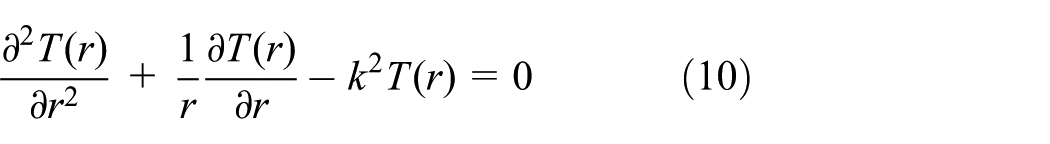
Equation (10) is correctional zero-order Bessel function. Because the pipeline is hollow, the general solution of equation (10) is

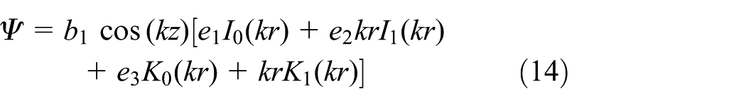
Substitute equation (11) into Ψ = T(r)cos(kz), the stress function, Ψ, can be expressed as

where four coefficients, a0, a1, b0, and b1, are solved by the boundary conditions of the pipeline, I0(kr) is the first kind correctional zero-order Bessel function, I1(kr) is the first kind correctional one-order Bessel function, K0(kr) is the second kind correctional zero-order Bessel function, and K1(kr) is the second kind correctional one-order Bessel function; the expressions are

where v is equal to 0 or 1.
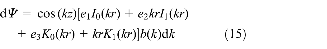
Assume a0 = e1b1, a1 = e2b1, b0 = e3b1, and equation (12) can be rewritten as
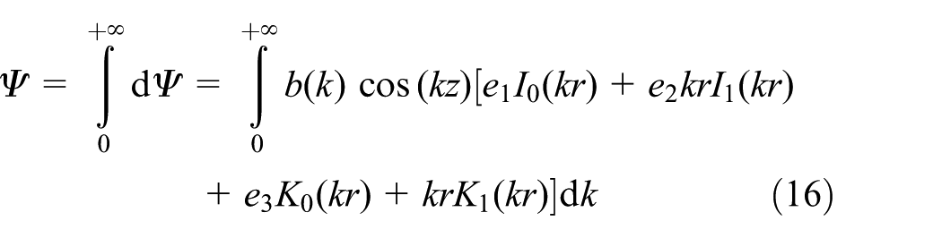
The stress function Ψ meets equation (6) regardless of the value of k. Substitute b1 = b(k)dk the equation (14) can be rewritten as
Equation (15) meets equation (6). Integrate equation (15) within (0, +∞), and the general solution of the stress function Ψ is
In o1r1z1, the force boundary conditions of the pipeline are

Because

So
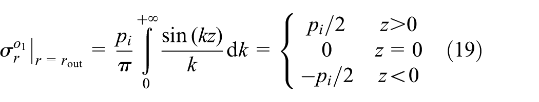
where rout is the outer radius of the pipeline and rin is the inner radius.
By solving equations (7), (13), and (16) with boundary conditions (17) and (19), the expressions (e1, e2, e3, b(k)) are

where


Substitute equation (22) into equation (16), and the stress function, Ψ, can be rewritten as
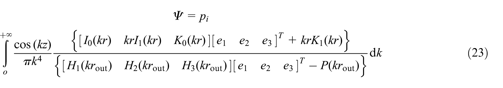
By solving equations (3), (4), (7), (8), and (23),

Based on elasticity method, physical equation and geometric equation of 3D axial symmetric model are


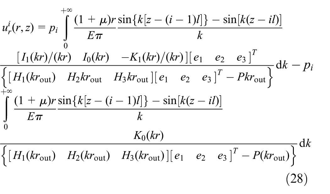
Using equations (24)–(26), the radial displacement of the pipeline can be obtained as

Verification of stress and displacement
In order to verify equations (24) and (27), stress components (

Stress and displacement: (a) distribution of
Figure 9(a) shows the distribution of stress
Displacement
The radial displacement
Contact pressure on sealing surface
According to the analysis of section “Equivalent model of contact pressure,” the radial displacement in a pipeline under n bands of contact pressure meets the superposition principle, and based on equation (28), the radial displacement is

If we choose n points at different locations of the pipeline, the radial displacement ur at point j is

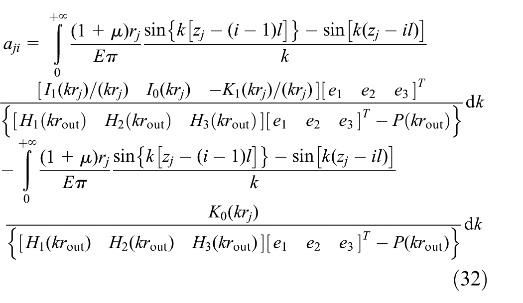
Solve equation (30) with n points radial displacements as the input, and contact pressure pi can be expressed as

where
When rj equals rout, equation (31) shows the relation between radial displacement on pipeline surface and contact pressure on sealing surface

When

Analysis of critical mean contact pressure
As the critical mean contact pressure,
When LAD is equal to 3 mm and rout is equal to 109.5 or 84.15 mm, the relation of the critical mean contact pressure and pipeline wall thickness is shown in Figure 10. The result indicates that the FEA result agrees with that of analysis and both of them decrease nonlinearly with the increase in pipeline wall thickness T. When rout = 109.5 mm, the critical mean contact pressure
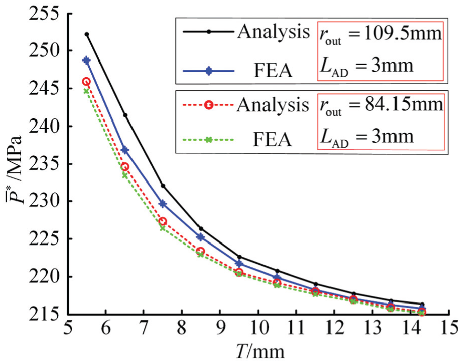
Relation of T and
When T is equal to 9.5 mm and rout is equal to 109.5 or 84.15 mm, the relation of the critical mean contact pressure and the width of sealing face is shown in Figure 11. The result indicates that the FEA result agrees with that of analysis very well and both of them decrease almost linearly with the increase in the sealing face width LAD. Under the same width of the sealing face, the critical mean contact pressures of different pipeline radial are nearly the same. When rout = 109.5 mm, T = 9.5 mm (rin = 100 mm) and LAD = 10 mm, the critical mean contact pressure

Relation of LAD and
Design of 8-in SPMC
Critical mean contact pressure
We take 8-in pipelines with API 5L standards (specification for line pipe) as an example to demonstrate the design of SPMC. The outer radius of the pipeline, rout, is 109.5 mm, the inner radius, rin, is 100 mm, and the yield strength, σs, is 235 MPa. According to the design rules for static metal seal, the yield strength of sealing ring should be higher than that of the pipeline, the material of press rings and the basic body is Q345, and its yield strength is 345 MPa. The Brinell hardness of pipeline, HB, is HB158. With regard to comprehensive factors such as sealing mechanism, lifetime, and loading force in installation, the width of sealing ring LAD is determined as 3 mm, so the value of z at B point is 0.8 mm and the value of z at C point is 2.2 mm. The LAD is divided into 20 sections with equal spaces and n is 20. Taking the above parameters into equation (34), the critical mean contact pressure for 8-in SPMC,
Finite element design
Structural parameters analysis
The contact pressure and contact uniformity on sealing face affect sealing performance of SPMC directly. In the design of SPMC, the contact pressure is replaced by the mean contact pressure and contact uniformity is expressed by contact pressure variance. If the mean contact pressure is higher than

Key variables of SPMC.
Finite element model
The structure of SPMC is axisymmetric and two-dimensional (2D) finite element model is established to save computing time. Because the structure of SPMC is complicated, in order to obtaining high-quality elements, the basic body and press ring are divided into some quadrilateral planes which can be meshed by a mapping method. The elements on the sealing faces are refined to improve the accuracy. The basic element is PLANE182, the contact element is CONTA172, and the target element is TARGE169. The finite element model is shown in Figure 13.
Finite element model.
Results of FEA
Figure 14(a) shows the distribution of the contact pressure on the major sealing face in the initial design. As the contact pressure variance is 40,316 MPa2, the contact of the sealing face is non-uniform, which explains the sealing face is line contact and tends to generate sealing failure. The mean contact pressure is 171.9 MPa and is less than the critical mean contact pressure of 223.34 MPa, which indicates the deformation of the sealing face is not enough and tends to form micro leak path. The distribution of the contact pressure on the major sealing face in the final design is shown in Figure 14(b). The contact pressure variance is 17795 MPa2 and decreases by 55.86%. The mean contact pressure is 245.2 MPa and is higher than the critical mean contact pressure of 223.34 MPa. Compared with initial design, the contact pressure increases and contact uniformity is improved in the final design, which can form a reliable seal.
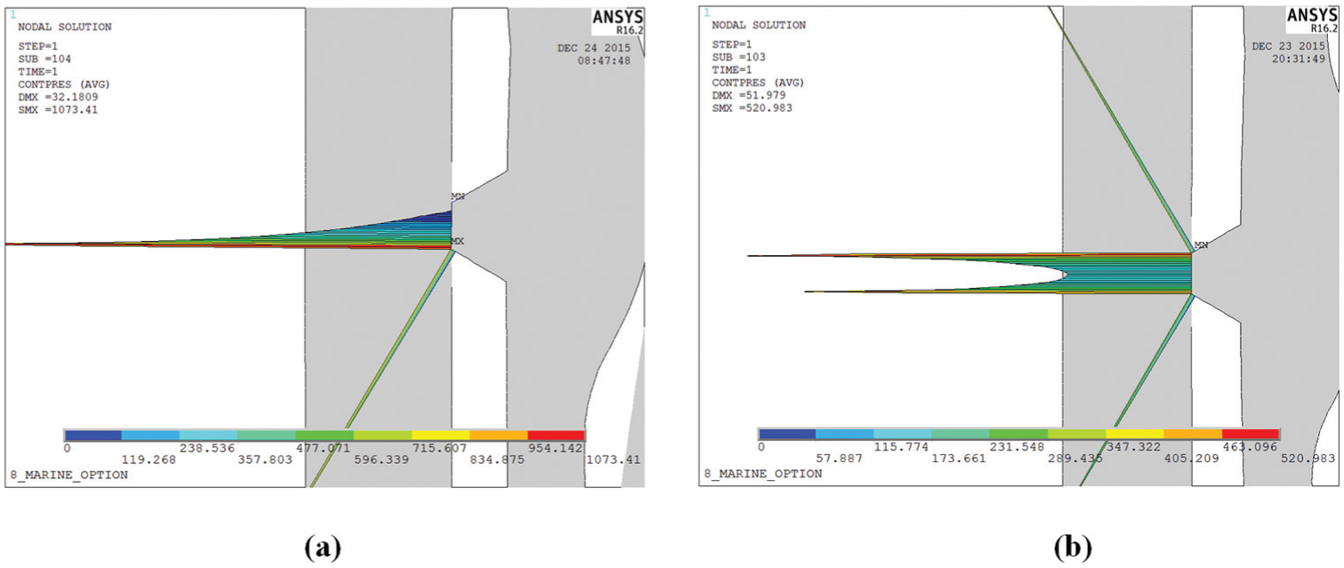
Contact pressure on major sealing face: (a) initial design and (b) final design.
Figure 15(a) and (b) shows the contact pressure of the initial design and that of the final design on the minor sealing face, respectively. The mean contact pressure of initial design is 148.8 MPa and the contact pressure variance is 20029 MPa2. The mean contact pressure of the final design is 262.6 MPa and higher than the critical mean contact pressure of 223.34 MPa. The contact pressure variance is 16912 MPa2 and decreases by 15.56%. The final design improves the sealing performance of the minor sealing face.

Contact pressure on minor sealing face: (a) initial design and (b) final design.
From Figure 16(a) and (b), the Mises stress of the pipeline approximately equals 197.95 MPa, which only makes elastic deformation on the pipeline. When SPMC is under complicated external load, there is enough elastic spring-back to keep the sealing. The Mises stress of the sealing rings and press ring is less than the yield strength, which will keep SPMC safe in operation. After the design of SPMC, the values of the variables are listed in Table 1.

Distribution of Mises stress of final designed SPMC: (a) major sealing ring and (b) minor sealing ring.
Value of variables.

Experiment
The design pressure of SPMC is 4.5 MPa. In order to validate that the critical mean contact pressure can form reliable sealing face for SPMC, the internal pressure experiments, indentation experiments of sealing faces, and the vibration experiments are carried out. These experiments have followed the experiment specification of the mechanical connector. 29 The experimental devices include two initial designed SPMCs, four final designed SPMCs, pressure gauge, shutoff valve, water hydraulic pump, pipelines, Instron8801 (vibration source), and so on. The medium is water and the temperature is 20°C.
The measurement range of the pressure gauge used in the experiments is 0–16 MPa and the minimum scale value is 0.5 MPa. The accuracy grade of the pressure gauge is 1.6 and full-scale error is 0.256 MPa.
Internal pressure experiments
The schematic diagram of the internal pressure experiments is shown in Figure 17. The internal pressure of 2 MPa is increased every 5 min by the water hydraulic pump. When the internal pressure reaches the given value, the shutoff valve is turned off to keep the pressure. When the internal pressure is increased up to a certain value, the value of pressure gauge starts to drop or leakage occurs, and this critical value is the sealing performance of SPMC. Figure 18 shows experiment facility of the internal pressure experiments.
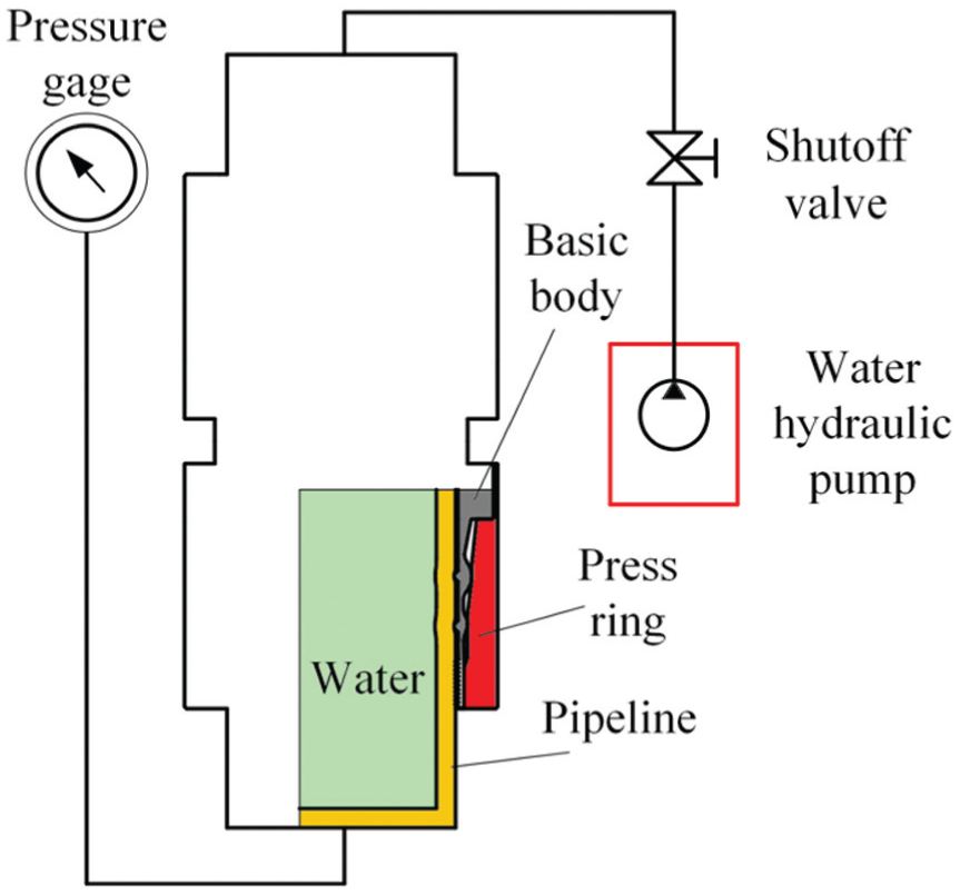
Schematic diagram of internal pressure experiment.
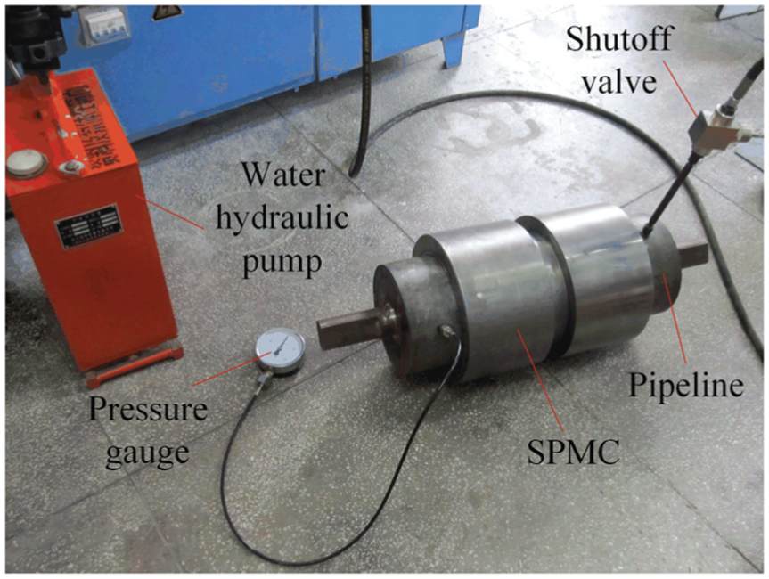
Facility of internal pressure experiment.
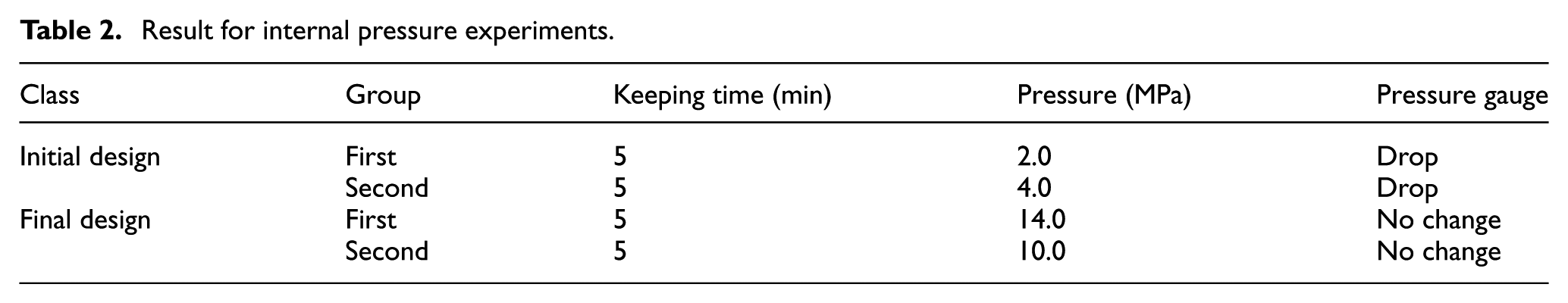
Table 2 is the results of the internal pressure experiments of the initial designed SPMCs and final designed ones. The results indicate that the sealing performance of the initial designed SPMCs is less than the design pressure of 4.5 MPa and that of the final designed ones is more than the design pressure. A pressure drop of 2.0 MPa can be seen in the experiment of the first one of the initial designed SPMCs and the reason is that there are some microdefects on pipeline surface and the micro leakage paths are formed under a low mean contact pressure. A pressure drop of 4.0 MPa is witnessed in the experiment of the second one of the initial designed SPMCs and the reason is that the sealing faces cannot contact fully and is linear contact with a big contact pressure variance, which tends to leak under internal pressure. The final designed SPMCs are designed with finite element method and its mean contact pressure is higher than the critical mean contact pressure of 223.34 MPa, which is enough to form a static sealing. The contact pressure variance is very small and the sealing faces fully contact. Larger mean contact pressure and smaller contact pressure variance will block leakage paths entirely. In the beginning of section “Solution of critical mean contact pressure,” when the internal pressure is higher, the sealing performance of SPMC is higher. Therefore, the SPMC is a self-tight seal and can resist a high internal pressure. Meanwhile, the result shows that the design method based on the critical mean contact pressure is valid for SPMC.
Result for internal pressure experiments.
Indentation experiments of sealing faces
To analyze the reasons to generate leakage for the initial designed SPMCs, the initial and final designed SPMCs are divided by wire-electrode cutting method and the indentation on pipeline surface is observed. One half of SPMC is shown in Figure 19.

Cutting part of SPMC.
Figure 20 shows the indentation on pipeline surface for the initial designed SPMC. The indentation locating in “A” point of the major sealing face is not continuous and the leakage occurs. When the internal pressure is increased to 2.0 MPa, a pressure drop occurs. That is because the mean contact pressure is less than the critical mean contact pressure, which cannot make microstructure on the sealing face generate enough deformation and micro leakage paths be blocked entirely. Although the indentation at “B” location is continuous, it is not uniform. The indentation depth locating at the bottom of the sealing face is more than that locating on the top of the sealing face and the real contact width is less than the critical width of 1.6 in. When the SPMC is under internal pressure, the seal fails easily. The mean contact pressure and contact pressure variance ensure the sealing performance of SPMC.

Indentation for initial designed SPMC.
Figure 21 shows the indentation on pipeline surface for the final designed SPMC. The mean contact pressure is higher than the critical mean contact pressure and the indentation on pipeline surface is continuous. On the partial enlarged observation, the sealing face has a similar indentation depth, the contact face is uniform, and the width is 3 mm. The sealing performance of SPMC is improved observably.

Indentation for final designed SPMC.
Vibration experiments
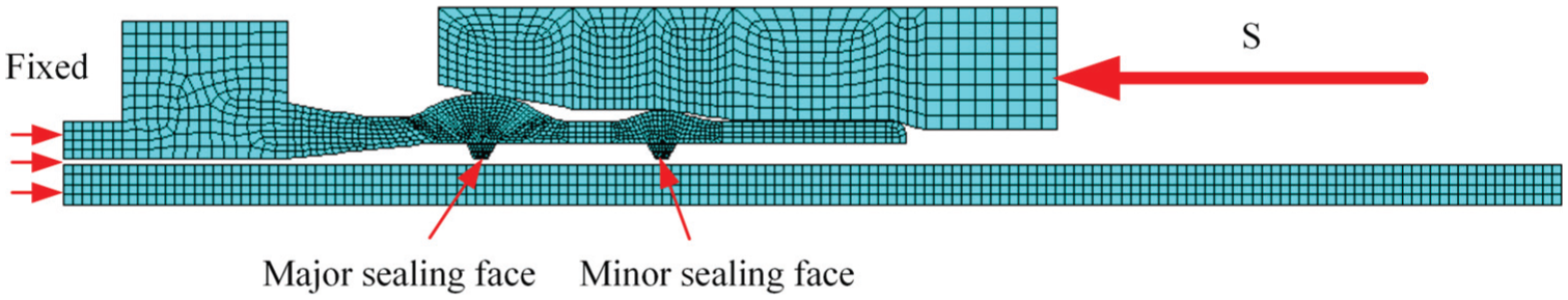
Because the initial designed SPMCs show a poor sealing ability in the internal pressure experiments, the vibration experiments are carried out only for the final designed SPMCs. The schematic diagram of vibration is shown in Figure 22. Based on experiment specification of the mechanical connector, 29 the vibration source (Instron 8801) provides the sine displacement wave, S = A sin(2πft), where the amplitude A is 0.097 mm and the frequency f is 20 Hz. When the cycle number of vibration is on the level of 107, leakage does not happen, which indicates the final designed SPMC meets the experiment specification of the mechanical connector. Before the experiments, the design pressure of 4.5 MPa is applied and the shutoff valve is turned off. Figure 23 shows experiment facility of the vibration experiments.

Schematic diagram of vibration.

Experimental facility of vibration.
Table 3 is the results of the vibration experiments of the final designed SPMCs. The cycle numbers of vibration are 10,029,670 and 10,004,652, respectively, which indicates the two final designed SPMCs meet the experiment specification. Therefore, not only does the SPMC-based critical mean contact pressure have a high sealing performance but also it has high ability in resisting vibration.
Result for vibration experiments.

Conclusion
The article investigated sealing mechanism of SPMC and established the critical condition of seal. On the basis of the superposition principle of elasticity, the formula of the critical mean contact pressure was deduced. The SPMC was designed with ANSYS and the sealing performance was verified by the internal pressure experiments, indentation experiments, and the vibration experiments.
According to the analytical analysis, finite element simulation, internal pressure experiments, indentation experiments, and vibration experiments, the following conclusions can be drawn:
Based on static metal sealing mechanism, the critical condition realizing reliable static metal seal for SPMC was established and the formula of the critical mean contact pressure was deduced.
By comparison of the analysis and FEA result of the critical mean contact pressure, the critical mean contact pressure decreases nonlinearly with the increase in pipeline wall thickness and decreases almost linearly with the increase in sealing face width. The radius of the pipeline has less influence on the critical mean contact pressure. The FEA result agrees with that of analysis very well.
The critical mean contact pressure of 8-in SPMC is 223.34 MPa which is used to design SPMC. The internal pressure experiments were carried out for both the initial and final designed SPMCs. The results indicate that the sealing performance of the final designed SPMC is higher than design pressure of 4.5 MPa and all the initial designed SPMCs failed in the experiment. The sealing performance of the final designed SPMCs is better than that of the initial designed ones.
By the observation on the indentation on the sealing face, if the mean contact pressure is less than the critical mean contact pressure, it produces discontinuous indentation and generates micro leakage paths. Meanwhile, the large contact pressure variance makes contact of sealing face non-uniform and leakage will occur under high internal pressure. The mean contact pressure and variance of final designed SPMCs meet design requirements, which forms uniform and continuous sealing face. The SPMCs designed by the critical mean contact pressure have good sealing performance.
The vibration experiments show that the cycle number of vibration of the final designed SPMCs is more than 107. The final designed SPMCs have good ability to resist both internal pressure and vibration.
In the next work in the soon future, we will develop auxiliary devices and further measure the contact pressure on the sealing surface by ultrasonic technology. By comparison of analysis, simulation, measurement, and experiment, the analysis and design method can be improved further. Once the SPMC is used to connect the pipelines in seabed successfully, it will strongly support offshore oil and gas exploitation.
Footnotes
Academic Editor: Michal Kuciej
Declaration of conflicting interests
The author(s) declared no potential conflicts of interest with respect to the research, authorship, and/or publication of this article.
Funding
The author(s) disclosed receipt of the following financial support for the research, authorship, and/or publication of this article: This work was supported by the National Natural Science Foundation of China (grant numbers 51279042, 51105088) and Royal Society International Exchange (grant ref. IE141319).