
Abstract
Based on the theory of gas lubrication and elastic mechanics, a theoretical model of gas-elastic coupling lubrication of compliant foil face gas seal (CFFGS) is presented. The correlation between the film pressure and thickness of CFFGS and its effect on the flow field are investigated, and the differential effect of pressure conditions on the flow field and sealing performance is analyzed. Also explored the influence law of operating and structural parameters on sealing performance. Results show that CFFGS have stable and excellent leakage control performance, and the pressure forms has a differential effect on the coordination mechanism of film pressure-deformation-film thickness and the sealing performance. Moreover, compliant foil structure has a positive impact on the end-face adaptive capability and leakage control performance of the seal.
Introduction
Mechanical face seals are widely used in shaft end seals of rotating fluid machinery due to their excellent sealing performance. 1 With the vigorous development of global industrial technology, petrochemical and energy industries have an increasingly urgent demand for sealing technology. Currently, dry gas seals (DGSs) are non-contact mechanical face seals with gas as the lubricating medium, which have become the mainstream of high-speed rotating fluid machinery shaft end seal applications 2 in virtue of the significant performance advantages of low leakage rate, low power consumption, and wear-free. However, under the influence of shafting excitation, installation deviation of sealing ring and other factors, the rotor and stator of DGSs are prone to wear and collision, thus leading to the failure of the seal. 3 In recent years, the petrochemical industry has experienced a high incidence of rotating fluid machinery failures which are caused by the failure of seals.4–6 There are two main causes for the failure, one is the uneven thermal deformation of the sealing face caused by the poor heat dissipation of the sealing ring, which in turn aggravates the wear of the sealing face, and the other is that the shafting excitation caused by the sudden change of operating conditions, which causes the collision of rotor and stator. Therefore, the development of a new type of gas face sealing technology with excellent heat dissipation and impact resistance is of great significance for solving the above problems.
In the 1970s, gas foil thrust bearings (GFBs) were gradually developed. GFBs are compliant fluid film bearings composed of several foils and a gas film generated by hydrodynamic viscous gas into the converging gap between the top foil surface and spinning rotor.7,8 Heshmat 9 proposed a design structure for a bump-type GFB, and achieved good results in the test. Heshmat et al. 10 used a linear stiffness spring model to simulate the deformation of the foil and investigated the static characteristics of a bump-type GFB. Heshmat 11 proposed a foil thrust bearing with a multilayer bump foil and demonstrated experimentally that this bearing has a large load-carrying capacity and high stability at high speed rotation. Dykas et al. 12 proposed a variable stiffness bump-type GFB, which realized the adjustment of the stiffness of bump foil to maximize the axial load-carrying capacity. After continuous improvement and optimization by scholars, GFBs was soon applied in engineering practice and showed remarkable excellence in high speed and wide temperature range conditions. At the beginning of the 21st century, Heshmat 13 and Agrawal 14 drew on the technical experience of the successful application of gas foil thrust bearings and designed the CFFGS, which consists of a bottom layer of bump foil and a top layer of top foil to form its elastic sealing face. Munson et al.15,16 verified experimentally that the CFFGS has good adaptability and excellent leakage control performance under extreme operating conditions such as 28,000–56,000 rpm and 593°C–760°C. Heshmat and Walton 17 put forward a theoretical prediction formula for the leakage rate of CFFGS, and experimentally explored the influence of structural parameters on the leakage rate. Heshmat et al. 18 explored the coordination between film pressure and foil deformation based on finite difference and finite element analysis, and experimentally proved that CFFGS is a low-leakage and high-efficiency gas face sealing technology for new hydrogen centrifugal compressors. Muson, 19 in a test based on the Rolls-Royce gas turbine platform, found CFFGS to be of great value for applications in gas turbine rotor thrust balance structures and turbine rims.
CFFGS combines the structural features and performance characteristics of gas foil thrust bearings and rigid surface face seals. Compared to conventional rigid surface face seals, CFFGS has the following advantages. First, elastic foil structure can provide cushioning force through foil deformation to prevent damage after the crash of rotor and static. Second, the sealing circulates a large amount of cooling gas into the hollow layer at the bottom of the foil, which absorbing the heat generated by gas-solid friction and effectively enhancing the heat dissipation capability. Third, the split design of the foil structure allows for independent deformation of each foil unit to maintain the stability of the seal, hence providing excellent self-adaptability.
Studies shows that CFFGS has good application prospects under extreme conditions of hypervelocity and high temperature, and is expected to drive a major innovation in gas face sealing technology. However, the operating mechanism of CFFGS still needs further investigations. Therefore, this study takes bump-type CFFGS as the object to establish the gas-elastic coupling lubrication model of CFFGS. The correlation between the film pressure and film thickness of CFFGS and its effect on the flow field are investigated, and the flow field and sealing performance of internal and external pressure type CFFGS are studied in comparison. The influence of operating parameters including medium pressure, rotational speed, and structural parameters including wedge height, slope ratio, foil-dam ratio, foil compliance coefficient, and number of foil on the sealing performance parameters is investigated to predict the variation pattern of sealing performance. Moreover, with the maximum stiffness-leakage rate ratio as the preferred target, the optimal range of structural parameters is determined. This study can provide theoretical guidance for the performance evaluation and structural design of CFFGS.
Theoretical models
Structure of CFFGS
The structure of CFFGS is shown in Figure 1(a), the elastic support structure of CFFGS is composed of bump foils and top foils, and the upper surface of the top foil forms a converging gap between the relative sealing surface, and the inner side of the sealing ring is the sealing dam which acts as a seal. Compared to the currently used dry gas seals with rigid surfaces, the elastic support structure of the CFFGS can adapt to changes in operating conditions through deformation to improve the operational stability and self-adaptability.

Structure of CFFGS: (a) model of CFFGS and (b) schematic of CFFGS.
The schematic of the CFFGS is shown in Figure 1(b). When the rotor rotates at a high speed, the rotor and stator move relative along the direction of converging gap reduction. The gas between the sealing faces is pumped into the converging gap to form a dynamic pressure effect, which generates a high-pressure gas film on the surface of the top foil, then the rotor and stator are pushed apart to form a layer of micron-level thickness of lubricating gas film.
Mathematical models
Theory of gas lubrication
Assuming that there is an isothermal, isoviscous, and ideal gas between the sealing faces, neglecting the effects of centrifugal and inertial force, then the steady-state Reynolds equation in cylindrical coordinates is 20 :

The dimensionless parameters are defined as follows:

The expression of the dimensionless steady-state Reynolds equation is:

The mandatory pressure boundary condition is:
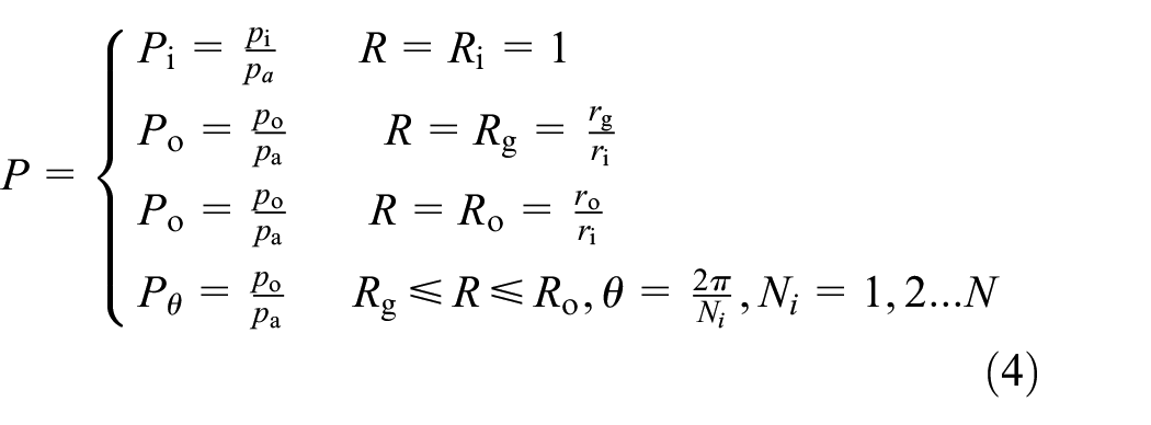
The periodic pressure boundary condition is:

Establishment of film thickness equation
The elastic face of CFFGS is composed of multiple fan-shaped foils with the same structure and shape. When the rotor and stator are operated without eccentricity and tilt, the film thickness distribution in each fan-shaped foil area is the same. 21 Since the elastic modulus of the rotor and stator materials is much greater than that of the elastic foil, and this study is based on a low-pressure sealed medium, thus the deformation of the sealing ring is minimal and can be neglected compared with that of the elastic foil. As shown in Figure 2(a), the plane section of the top foil is always flush with the sealing dam before the foil is deformed. Then the film thickness distribution as shown in Figure 2(b) can be established according to the structural characteristics of the foil.

Schematic of CFFGS: (a) geometric structure and (b) film thickness distribution.
According to Figure 2, the film thickness equation can be expressed as 22 :

where g(r,θ) expresses the height difference between the foil and the sealing dam, which is expressed as:

where u(r,θ) is the total axial deformation of the foil, which is expressed as:

In the above equations: b is slope ratio, representing the proportion of the slope section to the single fan-shaped foil.
Model of foil deformation
In this paper, the elastic bump foil is equated to a linear stiffness spring with a stiffness of kb, ignoring the stiffness of the top foil, the coulomb friction between the top foil and the bump foil, and between the bump foil and the sealing ring. 10 Then the relationship between the deformation of the foil and the film pressure is expressed as 22 :

The dimensionless form is expressed as:

where:

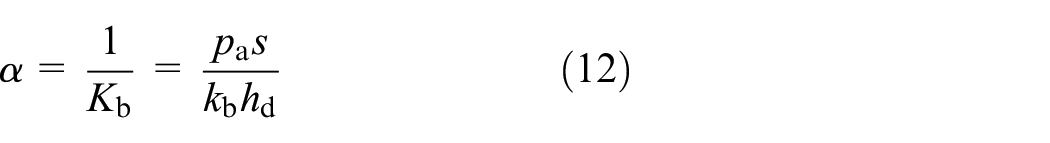
Compliance coefficient, which characterizes the ability of the foil to deform axially, is defined as 22 :
Calculation of sealing performance parameters
Opening force, resemble the load-carrying capacity of DGSs 23 and GFBs, 21 can be expressed as:

Gas film stiffness is defined as the ratio of the difference in opening force ΔFo to the difference in film thickness Δh, which must be a sufficient magnitude so as to suppress the drastic changes in film thickness:

According to the steady flow continuity principle, the leakage rate should not vary with radius. 24 The leakage of CFFGS occurs at the end face of the sealing dam. Ignoring the variation of the gas viscosity μ and the width of the sealing dam (rg–ri), the leakage rate is determined by the pressure of the inner and outer radius of the sealing dam and the balance film thickness h0, which is expressed as:

The definition of stiffness-leakage rate ratio Γ is the same as for DGSs, which comprehensively characterizes the stability and leakage control performance of the seal, and is expressed as:

Numerical solution of gas-elastic lubrication model
The dimensionless steady-state Reynolds equation (3) is solved by the finite difference method to obtain the film pressure and film thickness distribution, and then the sealing performance parameters such as opening force, gas film stiffness, and leakage rate are calculated.
Take the sector cell where any foil is located as the solution domain, then take the beginning of the gap section and the free end of the foil as the circumferential boundary, and the inner and outer radius of the seal as the radial boundary. Figure 3 shows a schematic diagram of the meshing of the solution domain in polar coordinates, with m nodes in the θ direction and n nodes in the r direction, for a total of m × n nodes. The density of the meshing is determined by both computational accuracy and computational time.

Schematic of mesh generation.
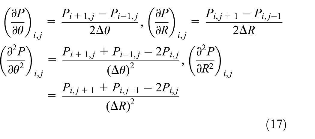
The dimensionless film pressure P in Figure 3 varies with node location, and the central difference method is used to discretize the variable P. The first and second order discretization formats for solving for the variable P at node (i, j) are as follows:
Equation (3) can be written in the standard form of a two-dimensional and second-order partial differential equation:
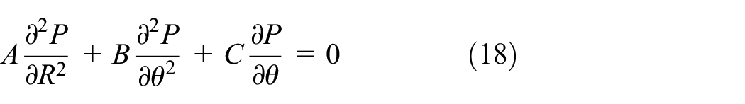
Substitute the difference equation of equation (17) into equation (18) to obtain the difference format of the partial differential equation (3), then the linear equation system of Pi,j at each node can be obtained. Finally, the mandatory pressure boundary conditions of equations (4) and (5) are introduced, the linear equation system is solved by the SOR (successive over-relaxation) iterative algorithm, and the convergence accuracy of the iteration is controlled by the convergence criterion equation (19).

Results and discussion
The basic calculation parameters are given in Table 1.
Initial parameters of CFFGS.

Operating mechanism of CFFGS
By analyzing the spatial distribution relationship between the film pressure and thickness of CFFGS as well as the flow velocity, the foil deformation and leakage control mechanism of CFFGS under high-speed conditions are discussed.
Figure 4 shows the film pressure, flow velocity, and film thickness distribution of CFFGS. As is shown in Figure 4(a), the pressure of the gap section is equal to the pressure of the outer radius side. This is because the deep gap is connected to the outer radius of the seal, and the gas is hardly affected by the dynamic pressure effect. The gradient of the film pressure in the slope section is obvious. With the decrease of the converging gap, the film pressure gradually rises and reaches the maximum at the junction of the slope section and the plane section. Backwards along the plane section, the pressure tends to be gentle and sharply decreases at the tail. The deformation law of foil in Figure 4(c) and (d) explains the above phenomenon. Firstly, the operation of the rotor pumps the gas to the converging gap, and the dynamic pressure effect increases as the film thickness decreases, hence the film pressure rises continuously and reaches the maximum at the beginning of the plane section. Secondly, due to the weakening of the dynamic pressure effect and the end leakage of the gas to the inner and outer sides, the film pressure in the plane section has a pressure drop in both circumferentially and radially. At last, corresponding to the film pressure distribution in Figure 4(a), the film thickness distribution in Figure 4(d) shows a pattern of large in the middle, small on both sides, and slightly decreasing along the circumferential direction in the plane section of the foil, which is consistent with the interaction law of film pressure-foil deformation-film thickness.

Spatial distribution of flow field: (a) film pressure, (b) fluid velocity, (c) film thickness (0 ≤ θ ≤ β3), and (d) film thickness of foil section (β1 ≤ θ ≤ β3).
The distribution of the fluid velocity field of CFFGS is shown in Figure 4(b). It can be seen in Figure 4(b) that the fluid medium basically flows circumferentially under the action of shear flow. Due to the obstruction of the slope, the flow velocity decreases abruptly when flowing from the gap section to the slope section. However, with the reduction of the converging gap in the slope section, the converging and squeezing of the fluid leads to a pronounced growth gradient of fluid velocity. And in the plane section, higher film pressure makes the fluid always maintains a higher velocity level. At the same time, larger radial film pressure gradient in the foil area makes the fluid medium obviously overflows to the low pressure area on both inner and outer sides. It can also be seen from Figure 4(b) that the concave deformation of the foil and the existence of the sealing dam obviously hinders the flow of fluid in the radial direction, which plays a significant role in preventing the leakage of high-pressure medium to the sealing dam along the foil surface.
Influence of pressure conditions on flow field and sealing performance
According to the position of the high-pressure sealed medium relative to the sealing ring, the CFFGS is divided into internal pressure-type (IPT) and external pressure-type (EPT). 25 As is shown in Figure 5(a), the rotor of CFFGS is mounted externally, therefore the high-pressure process fluid is located on the inner radius of the sealing ring. The gas pressure of the hollow layer at the bottom of the foil is the same as atmospheric pressure. In Figure 5(b), the rotor of CFFGS is mounted internally, the high-pressure process fluid is located on the outer radius side of the sealing ring accordingly. The gas pressure of the hollow layer at the bottom of the foil is the same as the pressure of the process fluid.

Pressure forms of CFFGS: (a) internal pressure-type (IPT) and (b) external pressure-type (EPT).
The selection of the above-mentioned pressure forms not only involves the switching of the inner and outer radius pressure boundaries, but also leads to different gas pressure conditions in the hollow layer at the bottom of the foil, which in turn has a differential effect on the coordination mechanism of film pressure-deformation-film thickness and the sealing performance. Therefore, this section focuses on the deformation coordination mechanism and the discrepancy of sealing performance under different pressure forms.
Take the average value of the film pressure and thickness from rg to ro, and draw the circumferential curves. Take the average value of the film pressure and thickness from bβ to β, and draw the radial curves. Figure 6 shows the comparative curves of the film pressure and thickness of IPT-CFFGS and EPT-CFFGS in the circumferential and radial directions. From Figure 6(a) and (b), it can be seen that the circumferential and radial film pressure of EPT-CFFGS are higher than those of IPT-CFFGS by 0.2–0.3 MPa. On the one hand, this is because the medium pressure at the bottom of the foil of EPT-CFFGS is higher than that of the IPT-CFFGS, which makes its equivalent supporting stiffness larger and the force deformation of the foil smaller, making it more conducive to the formation and maintenance of the dynamic pressure effect. On the other hand, the fluid pressure entering the upper surface of EPT-CFFGS is higher than that of IPT-CFFGS, making the hydrostatic effect of the EPT-CFFGS stronger as well. In addition, comparing the initial film thickness curves with the working film thickness curves in Figure 6, it can be seen that the foil deformation of EPT-CFFGS is larger than that of IPT-CFFGS by about 0.2 μm, which is directly caused by the higher pressure difference between the upper and lower surface of the foil of EPT-CFFGS. In summary, the selection of the pressure form has a major impact on the end-face flow field and the hydrodynamic and hydrostatic effects.

Average film pressure and thickness of IPT-CFFGS and EPT-CFFGS: (a) circumferential node and (b) radial node.
Figure 7 shows the comparison of sealing performance of CFFGS under different pressure forms. As shown in Figure 7(a) and (b), the opening force, gas film stiffness, and stiffness-to-leakage ratio of EPT-CFFGS are significantly superior to those of IPT-CFFGS. The advantage of EPT-CFFGS mainly benefits from the outstanding hydrodynamic and hydrostatic effects of its high medium pressure outside the sealing ring, as well as the equivalent support stiffness provided by the high-pressure medium at the bottom of the foil. Moreover, since the essential difference between EPT-CFFGS and IPT-CFFGS lies in the location of the high-pressure medium, their leakage rates are of equal value, but leak in opposite directions. In summary, the sealing performance of EPT-CFFGS is much better than that of IPT-CFFGS due to the excellent hydrodynamic and hydrostatic effects and the support force provided by the foil back pressure. Consequently, in the following section, the performance analysis and structural optimization are focused on EPT-CFFGS.

Sealing performance of IPT-CFFGS and EPT-CFFGS: (a) Fo and Kz and (b) Q and Γ.
Influence of structural parameters on sealing performance
This section focuses on the influence law of the structural parameters on the sealing performance of CFFGS (external pressure type).
Wedge height is defined as the maximum height difference between the slope section of the foil and the surface of the sealing dam. Figure 8 shows the influence of wedge height on sealing performance. As can be seen from Figure 8, the opening force, gas film stiffness, and stiffness-leakage rate ratio all increase first and then decrease with the increase of wedge height. The mechanism for this phenomenon is explained as follows. With the wedge height increases to the optimal range from 5 μm, the dynamic pressure effect is significantly enhanced, but if the wedge height continues to increase, the declivity of the slope section will be steeper, which causes the gas flow to the slope section be obstructed, thus weakening the dynamic pressure effect. Since the change of wedge height has no effect on the flow field at the sealing dam, the leakage rate in Figure 8(c) is not affected by the variable wedge height. In addition, the smaller the film thickness, the stronger the hydrodynamic and hydrostatic effects, which makes the maximum opening force and film stiffness at 3 μm increase by 51% and 140% respectively compared with 5 μm. Meanwhile, smaller film thickness at 3 μm allows a much lower radial leakage rate than 5 μm. The superposition of the above factors contributes to a superior comprehensive sealing performance (stiffness-leakage rate ratio) at 3 μm. Based on the above analysis and considering the comprehensive sealing performance, taking the maximum stiffness-leakage rate ratio as the target, the optimal range of wedge height is 7–10 μm.

The influence of wedge height on sealing performance: (a) Fo, (b) Kz, (c) Q, and (d) Γ.
As the slope ratio increases from 0.2 to 0.8, the leakage rate remains constant at different balance film thicknesses in Figure 9(c). As is shown in Figure 9(b) and (d), gas film stiffness and stiffness-leakage rate ratio all show a decreasing trend, while the opening force tends to increase slightly and then decrease significantly in Figure 9(a). More specifically, the maximum decreases in opening force and gas film stiffness are 23% and 44% respectively. Explanations for the above phenomena are as follows. Firstly, the increase of the slope ratio reduces the proportion of the plane section with high pressure and the hydrostatic effect is weakened consequently. Secondly, the increase in the slope ratio makes the declivity of the slope section smoother, which will lead to a weakening of the dynamic pressure effect. Moreover, since the hydrodynamic and hydrostatic effects are relatively weakened, the opening force, gas film stiffness, and stiffness-leakage rate ratio tend to vary more smoothly with the slope ratio at 5 μm. According to the comprehensive sealing performance, the optimal range of slope ratio is 0.2–0.3.

The influence of slope ratio on sealing performance: (a) Fo, (b) Kz, (c) Q, and (d) Γ.
Foil-dam ratio is defined as ξ = (ro−rg)/(rg−ri). Figure 10 shows the influence of foil-dam ratio on sealing performance parameters. As can be seen from Figure 10(a), as the foil-dam ratio increases from 0.4 to 2.3, the opening force at 4 and 5 μm decreases by about 15%–30% respectively, while the opening force at 3 μm increases. This is because the opening force provided by the foil area is insufficient to fill that lost in the area of the sealing dam at 4 and 5 μm. However, as the foil-dam ratio increases at 3 μm, higher film pressure makes the increased opening force of the foil fully compensate for the reduced opening force of the sealing dam. It can be seen from Figure 10(b) and (d), as the foil-dam ratio increases from 0.4 to 2.3, the gas film stiffness increases by more than 70%, and the stiffness-leakage rate ratio increased by more than 60%, this is because the increased high-pressure area of the foil results in a stronger load-carrying capacity and a greater equivalent gas film stiffness. In addition, the gas film stiffness and stiffness-leakage rate ratio increase with decreasing film thickness, and this trend is more prominent at larger foil-dam ratios. The above analysis shows that at the film thickness of 3 μm, the increase in foil area can significantly improve the load-carrying and anti-interference performance of gas film, which demonstrates the positive effect of the compliant foil on sealing performance. Moreover, with the increase of foil-dam ratio from 0.4 to 2.3, the leakage rate decreases by about 10−7 m3 s−1. According to the comprehensive sealing performance and engineering practice, taking the maximum stiffness-leakage rate ratio as target, the optimal range of foil-dam ratio is 1.5–2.
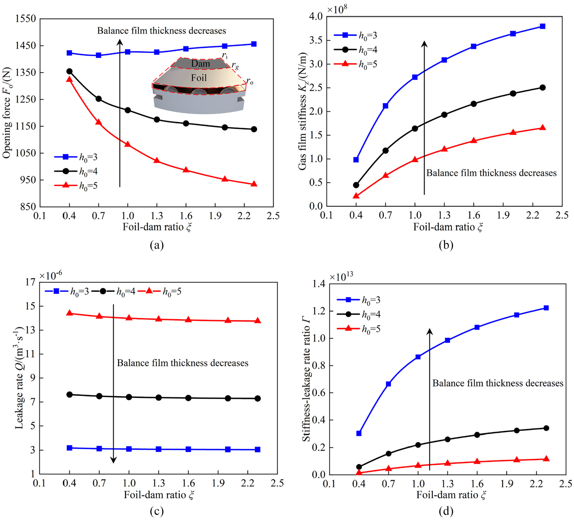
The influence of foil-dam ratio on sealing performance: (a) Fo, (b) Kz, (c) Q, and (d) Γ.
Figure 11 shows the influence of compliance coefficient on sealing performance parameters. In Figure 11, the opening force, gas film stiffness, and stiffness-leakage rate ratio all decrease with the increasing compliance coefficient, while the leakage rate remains constant. For the same balance film thickness, the maximum reduction in opening force is 23%, and the maximum reduction in gas film stiffness and stiffness-leakage rate ratio is approximately 40%. The reduction of the opening force is because larger compliance coefficient brings greater deformation of the foil. Therefore, under the coordination mechanism of film pressure-deformation-film thickness, the increase of the film thickness in the foil area causes the drop of film pressure, and finally decrease the opening force. In addition, under the excitation of the film thickness, larger compliance coefficient makes the foil reduce the effect of the excitation by increasing the amount of deformation, thereby maintaining the stability of the lubricating film. As a result, it can be seen that larger compliance coefficient will bring greater self-adaptability to CFFGS, but it will cause the loss of sealing performance. Furthermore, the opening force is lower at larger film thickness, which means the change of compliance coefficient will have a minor effect on the film thickness and the flow field, resulting in a smoother trend in sealing performance parameters. However, slight changes in compliance coefficient at smaller film thicknesses will have a greater effect on the flow field, which in turn leads to significant changes in sealing performance parameters. Consequently, in order to ensure good self-adaptability and excellent sealing performance in engineering, it is necessary to choose the compliance coefficient reasonably according to the actual engineering requirements.
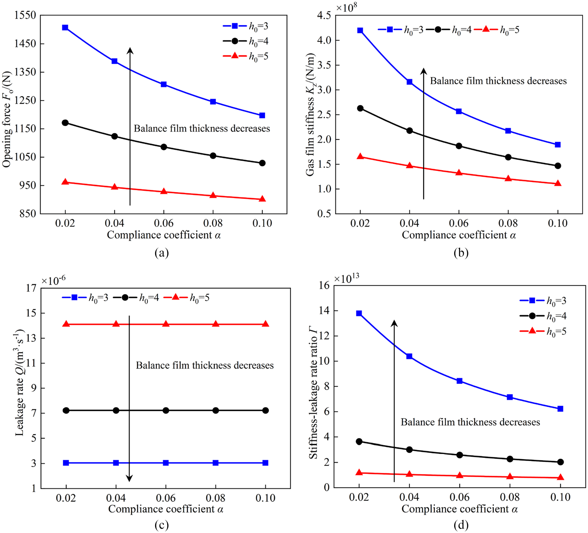
The influence of compliance coefficient on sealing performance: (a) Fo, (b) Kz, (c) Q, and (d) Γ.
Figure 12 shows the influence of number of foil on sealing performance parameters. As shown in Figure 12, the opening force increases steadily by about 24% as the number of foil increases from 4 to 12 at different balance film thicknesses, while the values of gas film stiffness and stiffness-leakage rate ratio increase slightly, and the leakage rate remains constant. The increase in opening force is due to the number of converging gap increases with the number of foil, thereby enhancing the dynamic pressure effect. In summary, number of foil only has an obvious impact on the opening force of the seal. Unlike other structural parameters, the above analysis and the results in Figure 12 indicate that the effect of foil number on sealing performance is almost independent of film thickness, which means the change in film thickness does not change the extent to which the number of foil contributes to the sealing performance. According to the comprehensive sealing performance, the optimal range of number of foil is 8–12.

The influence of number of foil on sealing performance: (a) Fo, (b) Kz, (c) Q, and (d) Γ.
Influence of operating parameters on sealing performance
This section focuses on the influence of operating parameters on the sealing performance parameters. Figure 13 shows the influence curves of medium pressure on the sealing performance parameters at different rotational speeds. As medium pressure varies from 0.1 to 0.9 MPa, it can be seen from Figure 13(a) and (c) that the opening force and leakage rate all increase at different rotational speeds. On one hand, the increase in the opening force is due to the enhanced hydrostatic effect at high medium pressures. On the other, the increase of the medium pressure leads to the enhancement of the effect of the differential pressure flow, which makes the rise of leakage rate. As shown in Figure 13(b), the gas film stiffness increases with the increasing medium pressure. From a limiting point of view, this is because the gas film stiffness is a measure of the degree of change in the gas film force at a perturbed film thickness, while the equivalent support stiffness of the gas film is greater at high medium pressures and therefore the gas film force against disturbance is stronger. Affected by the sharp increase in the leakage rate, the comprehensive performance index (stiffness-leakage rate ratio) in Figure 13(d) decreased rapidly, but the trend slowed down under high medium pressure. In conclusion, the appropriate increase in medium pressure and rotational speed has a positive effect on improving the load-carrying capacity and anti-interference performance, but it will also lead to a loss of leakage control performance. Therefore, under the circumstances of controllable leakage rate, the performance of CFFGS is preferable under large medium pressure and high rotational speed operating conditions.

The influence of sealed medium pressure on sealing performance: (a) Fo, (b) Kz, (c) Q, and (d) Γ.
Figure 14 shows the influence curves of rotational speed on sealing performance parameters under different balance film thicknesses. It is known from Figure 14 that the opening force, gas film stiffness, and stiffness-leakage rate ratio all increase with the increase of rotational speed, which benefits from the enhanced hydrodynamic effect brought by the increasing speed. In Figure 14(a), the hydrodynamic and hydrostatic effects of the gas are stronger at 3 μm, making the variation of rotational speed have a more significant effect on the opening force. Additionally, Figure 14(c) shows that the leakage rate is independent of the rotational speed, because there is no hydrodynamic effect and the change in rotational speed does not transform the pressure distribution of the sealing dam. As can be seen from Figure 14(d), the stiffness-leakage rate ratio at 3 μm is significantly greater than that of 4 and 5 μm, especially at high speed, which indicates the excellent comprehensive performance of CFFGS in high speed and small film thickness.
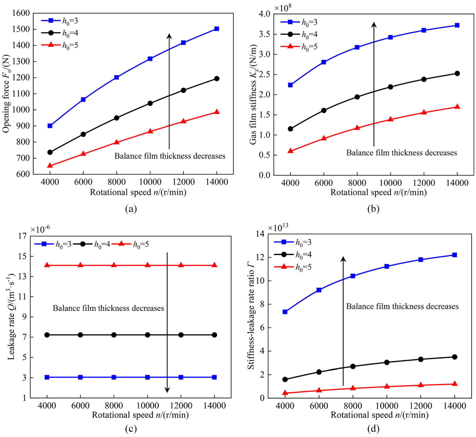
The influence of rotational speed on sealing performance: (a) Fo, (b) Kz, (c) Q, and (d) Γ.
Conclusions
By establishing the gas-elastic coupling lubrication model of CFFGS, investigating the operating mechanism and sealing performance. Results reveals that CFFGS can guarantee excellent leakage control under the outer radius linear velocity of 25–100 m s−1 and medium pressure of 0.3–0.9 MPa. Meanwhile, it can provide sufficient opening force and gas film stiffness for the operation of the seal.
For EPT-CFFGS, higher foil back pressure and end-face film pressure than that of IPT-CFFGS provides it with greater equivalent supporting stiffness and stronger hydrodynamic and hydrostatic effects, which makes the load-carrying capacity and anti-interference performance of EPT-CFFGS significantly outperforms that of IPT-CFFGS.
Although the compliant foil face will lead to a certain loss of sealing performance, it has a significant effect on enhancing the self-adaptive ability of the sealing face under the influence of film pressure and film thickness. At the same time, the concave deformation of the compliant foil has a hindering effect on the radial flow of fluid, which has a positive implication on enhancing the leakage control performance of the seal.
Under the scope of the parameters studied in this paper, comprehensively considering sealing performance and engineering practice, the optimal range of structural parameters for CFFGS is initially determined with the maximum stiffness-leakage rate ratio as the preferred target. The slope ratio is between 0.2 and 0.3, the foil-dam ratio is between 1.5 and 2, the number of foil is between 8 and 12, the wedge height is between 7 and 10 μm.
Footnotes
Appendix
Handling Editor: Chenhui Liang
Declaration of conflicting interests
The author(s) declared no potential conflicts of interest with respect to the research, authorship, and/or publication of this article.
Funding
The author(s) disclosed receipt of the following financial support for the research, authorship, and/or publication of this article: This work was financially supported by the National Natural Science Foundation of China (Grant Nos 51905513 and 52005470), the Postdoctoral Science Foundation of Zhejiang Province, China (Grant No. ZJ2020084), and the Fundamental Research Funds for the Provincial Universities of Zhejiang (Grant No. 2021YW07).