
Abstract
In order to realize the precision plastic forming of the revolving body component with changeable wall thickness, a kind of roller containing grooves with changeable inner diameter is put forward, as the forming mould of the technology of rolling-extrusion. Specifically, first, the arc length of the groove in the roller is designed according to the prediction on the forward slip value during the process of forming, to make accurate control of the actual length of the forming segments; then, to obtain better parameters of the roller structure, a second-order response surface model combining finite element numerical simulation and response surface methodology was put forward, taking the factor of forming uniformity as evaluation index. The result of the experiment shows that, for the formed component, not only the size can meet the needs but also each mechanical property index can be greatly improved, which verify the rationality of the forward slip model and the structural parameter of the optimum model based on the response surface methodology.
Introduction
With the development of the modern war, in order to enhance the lethality and mobility, the heavy calibre projectile body with changeable wall thickness revolving body appearance is raised to the predominant position. As a result, the production of tubular components with changeable wall thickness is greatly improved. For producing general tubes, various methods such as extrusion, hot forging, roll forging and rotary piercing might be used. However, as to the manufacturing of this kind of the revolving body component with changeable wall thickness, only the technology of hot extrusion-drawing has been widely used. In specific, the billet is first processed into the straight-wall cylinder with the method of hot extrusion-drawing and then cut into the curved appearance by machining process. 1 However, for the component processed by this technology, the usage of material is very low (less than 30%), the consumption of cutter is great and the cost of production is high. Fortunately, with the advancement of the modern industry, the traditional plastic forming technology is being directed into the orientation of light weight, accuracy and integration, and the orientation of national defence industry is being directed into conserving energy, reducing emissions and decreasing composite cost. In this background, some new processes are tried to apply to the production of this component, such as hot spinning and cross-wedge rolling. However, the inner cavity shape of the component may be changed with the process of cross-wedge rolling, and the workpiece is difficult to be separated from the punch, with the process of hot spinning. What is more, the production efficiency is low. Therefore, the technology of rolling-extrusion is put forward, with a kind of roller containing grooves with changeable inner diameter as the forming mould. It is worth noting that the component can be processed by plastic forming directly, with this method, and the biggest advantage of this technology is that the wall thickness of the workpiece can be continuously decreased, so as to form the revolving body with changeable wall thickness. However, currently, because the rolling-extrusion is a kind of new technology, there is not yet any report about the design on this kind of roller with changeable inner diameter groove.
In recent decades, with the rapid development of computer technology, finite element method (FEM) has been widely used in simulation of profile extrusion processes.2–6 What is more, the technology of finite element (FE) simulation is widely used in the design on the mould, which greatly cuts down the cycle of design and shows huge advantage.7–9 For the precision of a forged titanium-alloy turbine blade, Morita et al. 10 used FE simulation to define the optimum position of the billet. Lapovok 11 optimized the design of the preform with reference to die-life and damage accumulation. Sheng and Guo 12 proposed a reverse simulation technique for process design based on the upper bound element technique (UBET). In addition, the response surface method, proposed by Box and Wilson in 1951, is a kind of method that the complex and unknown functional relationships are fitted together by the simple mode of first-order or quadratic polynomial within a small area and has been widely used in the optimum design on the drawing process and mould of panel;13–15 Such as Roy et al. 16 applies genetic algorithm into the optimum design on the shape of performing mould for forging workpiece. In this article, taking the realization of near net forming of this kind of component as the principle, a whole design scheme on the roller with changeable inner diameter groove is put forward, and an optimum design on the structural parameter of the roller is made with the aid of finite numerical simulation as well.
Principle of the rolling-extrusion technology
As shown in Figure 1(a), the component is a revolving body component with changeable wall thickness, and the billet for this kind of component can be seen in Figure 1(b). In addition, for the forming of this component, the difficulty is how to form the three parts with different wall thickness in one forming. In this article, the technology of rolling-extrusion is adopted to form the component shown in Figure 1(a). In specific, rolling-extrusion is a kind of new technology that the metal is made to produce continuous local deformation within a closed die cavity composed of three rollers, as shown in Figure 2(a). Moreover, in this technology, when the cylinder billet (as shown in Figure 1) is drove to move downwards by the punch, under the action of friction, the rollers are drove to rotate inwards synchronously, and then seize and extrude the billet, so as to make the wall thickness of the cylinder billet to become thinner and extend along the axial direction. In addition, as shown in Figure 2(b), the tangential curve of the groove in the roller is not a right circle, but a structure composed of the arcs with different radii, therefore, when the billet is extruded, the quantity of the wall thickness decreased can be controlled by the radii of the arcs.
Geometry of (a) the component and (b) the billet.

Schematic illustration of rolling-extrusion forming principle: (a) the three-dimensional diagram and (b) the plane diagram.
The whole design of roller
The whole design of the roller is shown in Figure 3(A). From the figure, it can be seen that three grooves are cut out in the roller to make the control on the forming of the workpiece. Hereinto, the design on the cross section of the groove is shown in Figure 3(C). From this figure, it can be seen that the design on the groove is a structure of one-third arc, so as to ensure the close of the groove in the roller is a closed circle. In addition, the three radii of the grooves are in accordance with that of the three forming segments of the component shown in Figure 1(a).

The overall design diagram of the roller: (A) schematic model of the roller; (B) tangential cross-sectional diagram of the grooves; (C) circumferential cross-sectional diagram of the groove: (a) the first groove, (b) the second groove and (c) the third groove; and (D) structural parameters of the roller.
The circumferential cross section of the groove in the roller is shown in Figure 3(B). Theoretically speaking, the length of the forming arcs should be equal to that of the forming segments in the component; however, due to the problem of the forward slip, the actual length should be worked out through an accurate calculation. Therefore, the author of this paper makes a deduction on the forward slip of the technology of rolling-extrusion, 17 as shown in equation (1)

In this equation,
Provided that the length of the three forming arcs is

Moreover, because the condition of flash can easily be caused during the process of forming, a gutter is cut out in the close part of the roller, as shown in Figure 3(D). From the figure, it can be seen that the main structural parameters are given, including the equivalent radius L (the distance from the axis of the roller to that of the groove), the width of the roller D and the apex angle of the gutter
The FEM and experimental methods
In this study, the 50SiMnVB alloy steel is used in the experiment, and Table 1 illustrates the composition of the material used. Moreover, the material flow stress constitutive equation is determined by stress–strain curves presented in Liu et al. 18
Chemical compositions of 50SiMnVB (mass fraction, %).

Establishment of FE simulation model
The DEFORM 3D-6.1 software is used for FE simulation, and the material model is defined as thermal coupling rigid visco-plastic.19,20 Moreover, all the die parts are considered as rigid bodies, and the billet is defined as deformable object during all the analyses, which is divided into 85,844 tetrahedron elements with 15,482 nodes. In addition, the shear friction driving model is taken as the friction coefficient with a friction factor of 0.3. Furthermore, the initial temperature of the billet is set as 1050°C, the temperature of the rollers and die is set at 150°C and the surrounding temperature is set as 20°C. Apart from that, the contact heat conductor coefficient is 11 W/(m2 K), the heat exchange coefficient is 0.02 W/(m2 K) and the downward speed of the punch is set as 16 mm/s.
Experimental methods
In this experiment, the rollers are made from hot work steel H13 and hardened up to 55 HRC. Figure 4(a) illustrates the rolling-extrusion forming setup, and Figure 4(b) is the experimental setup of 630-ton hydraulic press. In addition, the extrusion is made under the pressing of the punch drove downwards with a speed of 16 mm/s, and the water-based graphite (water (2000 mL, 60–80°C) + dispersant (50 mL) +surfactant (35 mL) + graphite powder (400 g) + inorganic salt (200 g)) is used as the lubricant.

Setup used in the experiment: (a) rolling-extrusion forming setup and (b) experimental setup.
Results and discussion
Optimization on the structural parameter of the roller
Based on the optimized method for the approximate model of surface methodology, an optimization on the structural parameter of the roller is made, and the target of the optimization is the evaluation factor of forming uniformity

Hereinto,
Design on the range of the structural parameter of the roller
From the geometrical relationship shown in Figure 6, it can be concluded

In this equation,
Moreover, according to Metallurgical Machinery Design Manual,
In addition, as shown in Figure 5, with the enlargement of the apex angle of the gutter, the factor of the forming uniformity is decreased first, and then increased, hereinto, within the range of (25°, 35°), and the result is better.

The influence of the apex angle on the forming uniformity.
Design of the experiment of numerical simulation and analysis on the result
In this experiment, the method of central composite design is adopted as the design method, the designed variables are selected within the range shown in Table 2 and a matrix is designed to select the samples and values according to the three-factor and three-level centre composition. Then, 15 groups of experimental schemes are worked out to make the numerical simulations respectively. Finally, the factors of forming uniformity are calculated, as shown in Table 3.
Design on the range of the structural parameter of the roller.

Result of the numerical simulations.

All the coefficients are estimated and tested by applying ‘F-test’ using trial version of Design-Expert software, for their significance at a 95% confidence level. After determining the significant coefficients, the final model was developed to predict forming uniformity as follows

The result of F-test shows (Table 4) that the fitting degree of the model (R2) is so high that it can reach 99.78%, the correction coefficient is 98.81% and the value of p is 0.013. All these indicate that the prediction accuracy of the model is high, and the influence of the model on the response value is very remarkable. In addition, the most optimum solution to the forming uniformity is 1.49432. Furthermore, the most optimized assemblage of the structural parameters of the roller is that the distance of the axis is 190, the apex angle of the gutter is 30 and the width of the roller is 130.
Analysis of variance of the regression equation for forming uniformity.

R2 = 99.78%; R2 (adj) = 98.81%.
Measurement of the size
Figure 6 is the diagram of one of the pilot samples. From this figure, it can be seen that the initial site of forming is accurate, and the joints among the three forming segments is very neat. Moreover, measurements on the length and the wall thickness in the three forming segments of the 50 pilot samples formed in the experiment are made by a special measuring tool, and the average length is shown in Table 5. For the three forming segments of all the samples, both the results of numerical simulation and physical experiment results are very close to the requirement value, and the maximal error in the average lengths is no greater than 1.07 mm. As shown in Figure 7, the average wall thickness distribution of the 50 pilot samples formed and FEM is compared. The experimental results are in good agreement with the FEM, and the maximum relative error is 1.33%. All these indicate that during the process of forming, the prediction on the forward slip is more accurate, and the effect of the control on the size of the workpiece is more demonstrable.
One of the pilot samples.
The lengths size contrast.
The contrast of wall thickness values obtained by FEM and experiment.
For one single workpiece, the consumption of the material is 24.1 kg in the traditional forming technology described in the ‘Introduction’ section, and the consumption of the material in the designed forming technology in this article is 17.3 kg. Therefore, it can be concluded that the consumption of the material in the designed technology can be saved 6.8 kg, and the utilization ratio of the material can be improved by 9.8%.
Figure 8 is the sectional view of the formed workpiece. From this figure, it can be seen that the distribution of the wall thickness of the forming segment is uniform, and there is no fold and crack in the sectional view of the formed workpiece. In addition, the metal flow of the workpiece is reasonable judging from the whole streamline.

Sectional view of the formed workpiece.
Test on the performance
Sampling is made according to the positions indicated in Figure 9, so as to make a test on the mechanical performance of the workpiece, and the result is shown in Table 6 (after heat treatment). Heat treatment process: 860°C quenching, heat preservation for 90 min, 520°C tempering and heat preservation for 120 min – air cooling. As shown in Figure 9, TQ = 860°C, TT = 630°C.
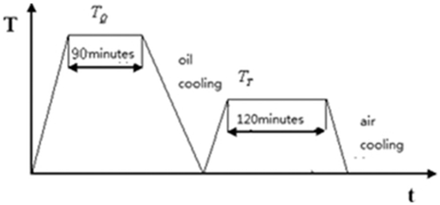
Heat treatment process.
Mechanical performance of the workpiece.

It can be concluded that each index not only can meet the needs for the production but also is improved greatly comparing with that of the traditional forming technology. The HRC measurement values of the three different workpieces are much closer, which proves that the deformation of the workpiece is uniform in the process of forming and verifies the rationality of the structural parameter of the optimum model based on the response surface methodology.
Conclusion
The revolving body component with changeable wall thickness can be formed by the designed roller in this article; under the condition of the performance meeting the needs, the utilization ratio can be improved by 9.8%. Therefore, if the technology is used in the practical production, the consumption for the prime steel will be saved greatly.
The design scheme of the rolling mould with changeable inner diameter groove proposed in this article not only realizes the accurate control on the size of the workpiece but also makes a better control on the forming uniformity and improves the mechanical performance of the workpiece as well.
In this article, the rationality of the forward slip model and the structural parameter of the optimum model based on the response surface methodology are all verified; therefore, this undoubtedly can provide a theoretical support for the application of this kind of rolling mould.
Footnotes
Academic Editor: Michal Kuciej
Declaration of conflicting interests
The author(s) declared no potential conflicts of interest with respect to the research, authorship, and/or publication of this article.
Funding
The author(s) disclosed receipt of the following financial support for the research, authorship, and/or publication of this article: This work was supported by The Base of National Defense Scientific Research (A3320110002).