
Abstract
A constitutive model based on the Johnson–Cook material model and the extended Drucker–Prager strength criterion was implemented in LS-DYNA to simulate the rock failure process induced by a single disk cutter of a tunnel boring machine. The normal, rolling, and side forces were determined by numerical tests. The simulation results showed that the normal and rolling forces increased with increasing penetration while the side force changed little. The normal force also increased under the conditions of confining pressures. The damage region of rock and cutting forces were also obtained by simulation of two disk cutters acting in tandem with different cutting spacings. The optimum ratio of cutter spacing to penetration depth determined from numerical modeling agrees well with that obtained by linear cutting machine tests. The average normal and rolling forces acting on the first cutter are slightly greater than those acting on the second when the cutting disk spacing is relatively small. The numerical modeling was verified to accurately capture the fragmentation of rock induced by disk cutter.
Introduction
Tunnel boring machines (TBMs) have been widely used in tunnel construction for a variety of purposes such as highways and subways. The cutter-head design is one of the critical aspects of the TBM manufacturing process. The head diameter, number of cutters, thrust force, rolling force, penetration depth, and cutter spacing are the important parameters in head design. Among these, the cutting forces and appropriate cutter spacing are the main factors governing cutting efficiency. 1 Disk cutters are the main tools employed by TBMs for fragmenting rock. However, this essential component is easily worn. It is, therefore, necessary to analyze the cutting forces acting on a disk cutter and determine its failure mechanisms for better TBM head design and improved cutting efficiency.
For determination of the forces acting on TBM disk cutters and for establishing optimum cutting settings, full-scale linear cutting machine (LCM) test has been proved to be a reliable method.2–5 Although full-scale tests have significant advantages, they are expensive and time-consuming. 1 To overcome these deficiencies, well-known prediction models, for example, Colorado School of Mines (CSM) 6 and Norwegian University of Science and Technology (NTNU), 7 have been developed to predict the performance of TBMs. Numerous examples of theoretical and semi-theoretical formulas can be found in the literature.8–13 However, these simple analytical models can provide only an approximate estimation of the cutting forces. Barton 14 introduced a predictive formulation of TBM performance using the rock mass quality index (QTBM). Rock mass classification systems such as the Q-system and rock mass rating (RMR) system have also been used for the estimation of TBM performance. 15 Zhao et al. 16 established a prediction model of TBM performance using ensemble neural network analysis for granitic rock masses. Empirical prediction models are mainly established according to experience and previously recorded data in the field. The accuracy and reliability of these models depend on the quality and amount of the data available. It is generally difficult to collect substantial amounts of high-quality data.
Numerous researchers have applied numerical modeling to simulate the fragmentation of rock by TBMs. The prediction of the fragmentation process during rock cutting using various numerical methods was reviewed in detail by Menezes et al. 17 Most studies have focused on the modeling of linear slab cutting due to its simplicity. Several methods have been used to simulate the cutting process such as the finite differential method (FDM), displacement discontinuity method (DDM), discrete element method (DEM), and finite element method (FEM). For example, the FLAC program employs an explicit FDM for computational engineering mechanics applications. Park et al. 18 developed a heterogeneous two-dimensional (2D) model using FLAC to evaluate the effect of confining pressure and cutter spacing on the fragmentation of rock. Innaurato et al. 19 studied the rock fracture and chipping formation of a TBM disk cutter. The authors used Mohr–Coulomb material constitutive model for the rock. Tulu and Heasley 20 adopted the commercial three-dimensional (3D) FDM code FLAC3D to simulate circular groove cutting. A rock indentation model was developed by Tan et al., 21 in which a modified energy criterion was incorporated into a DDM code. DEM and FEM are, however, the most widely used numerical methods for rock-cutting analysis. In fact, of these two, the FEM is clearly the most commonly employed numerical method for all engineering sciences, including rock mechanics and rock engineering. 22 Gong et al.23–26 explored the effect of joint spacing and orientation on rock fragmentation using universal distinct element code (UDEC) based on a 2D DEM. DEM has also been used by Rojek et al.27,28 for the simulation of rock-cutting processes. Moon and Oh 29 employed the commercial 2D DEM code PFC2D to simulate the optimal rock-cutting phenomena according to the ratio of the cutter spacing to the penetration depth (s/p) using the properties of intact rock. Su and Akcin 30 and Mendoza Rizo 31 employed the 3D DEM code PFC3D to predict cutter forces from cutting tests. Huang et al.32,33 employed a DEM to study the failure mechanisms induced by a wedge-shaped tool indenting normally against a rock surface. Tang 34 developed a numerical approach denoted as rock failure process analysis (RFPA) based on FEM. Tang et al. 35 simulated the fracture of rock containing grains or inclusions using RFPA. Liu et al. 36 simulated rock cutting with the FEM code R-T2D to evaluate the rock fragmentation process induced by single and double indenters. Cho et al. 1 employed FEM with explicit time integration software AUTODYN-3D to simulate the failure process of rock observed during LCM test. Yu 37 employed LS-DYNA software to simulate the rotation of a continuous miner cutter head while cutting rock. Jaime 38 reproduced the failure mode in linear cutting using LS-DYNA software and successfully modeled the crushing failure mode in shallow cutting and the crack initialization, crack propagation, and dynamic fragmentation in deep cutting.
While the DEM and FEM are most commonly employed for modeling rock-cutting process, they have their individual strengths and weaknesses. Although the DEM is able to model the majority of primary rock-cutting phenomena, the material model must be built at the micro-level. However, the FEM employing continuum damage models is able to model both the ductile and brittle damage modes. Hence, this method was adopted for this study. The FEM can also provide detailed information on the distribution of stresses, strains, and strain rates in the chip formation zone. This detailed information cannot be easily obtained using other methods such as analytical and experimental or empirical methods. 17 This study employed the explicit FEM code LS-DYNA, which is capable of capturing dynamic interactions during rock cutting.
The rock-cutting process is a complex dynamic process with complicated nonlinear characteristic, and the numerical modeling of the process requires a detailed constitutive material model for rock that can account for the complicated behavior of rock under various conditions of stress. The strength of rock is usually a function of pressure, strain rate, temperature, and damage. Various models have been used such as the elastic, von Mises, Mohr–Coulomb, Drucker–Prager, and Hoek–Brown models. The Mohr–Coulomb and Drucker–Prager failure criterion have typically been utilized for modeling rock materials in the numerical simulation of the rock-cutting process, although they considered only the influence of static stress. The effects of high confining pressure and strain rate and temperature on rock strength are not considered. This article presents a rock damage material model based on the Johnson–Cook material model 39 and extended Drucker–Prager strength criterion, 40 which considers temperature, confining pressures, and strain rates. The damage model is applied to analyze the rock damage induced by TBM disk cutters.
Material constitutive model for rock
The selection of constitutive models for rock failure plays an important role in rock mechanics and rock engineering, especially in the fields of numerical modeling. 38 The compressive strength of rock is increased with increasing lateral confining pressure and strain rate and decreased with increasing temperature. A reliable computational material model for rock should include features such as the combined hardening of the strain rate and pressure, the softening effect of high temperature. This article presents a rock material model that considers confining pressures and strain rates and temperature, based on the Johnson–Cook model 39 and extended Drucker–Prager strength criterion. 40
The yield surface of rock can be expressed as a function of hydrostatic pressure, strain rate, temperature, and damage. The specific expression is

where
The deviatoric stress measure
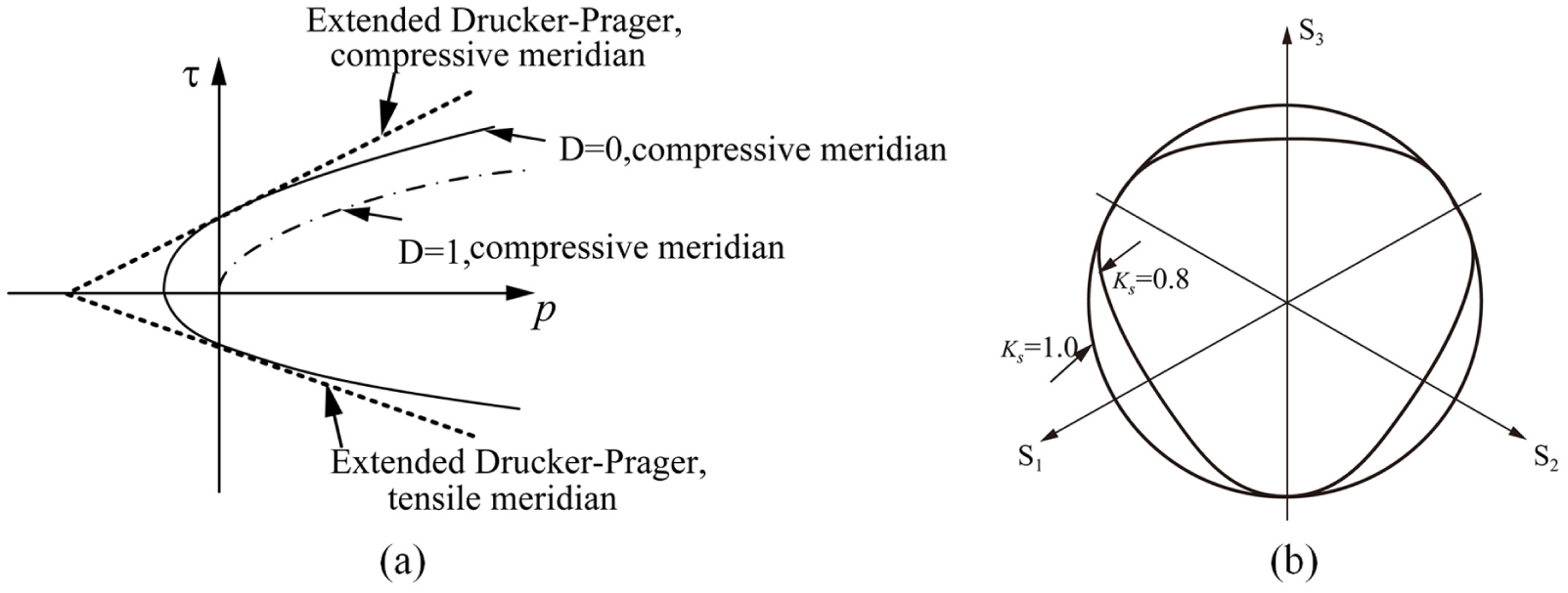
Failure criterion adopted in the material model: (a) in the meridian plane and (b) in the deviatoric plane. 40
The hydrostatic pressure is calculated by the equation of state, which has identical form with the original article of Holmquist et al.
41
The equation of state defines the hydrostatic pressure–volume relationship. The volumetric strain can be expressed in terms of the principal strain
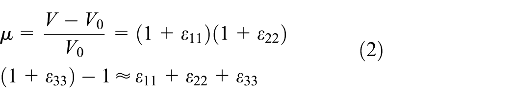
where

Relation of pressure and volumetric strain.
The nonassociative plastic flow rule is used to describe the plastic strain rates. The plastic potential

The rate of plastic strain is given as follows

where
The damage from fracture is accumulated in a manner similar to that used in the original Holmquist–Johnson–Cook (HJC) model. 41 The damage accumulating from equivalent plastic strain and plastic volumetric strain is expressed by the compressive damage parameter

where

where
Numerical simulation results and analysis
We used the 3D FEM numerical code LS-DYNA to simulate the rock failure process induced by disk cutter, which is capable of simulating nonlinear and dynamic fracture failures. The rock material model presented in the previous section was implemented in LS-DYNA via the user subroutine UMAT.
Single disk cutter rock fragmentation process
Finite element model of the rock and disk cutter system
In the numerical simulation process, the parameters for Colorado red granite with uniaxial compression strength of 158 MPa were used, 4 based on the material model described in section “Material constitutive model for rock.” The material parameters are listed in Table 1. The size of the modeled rock specimen was 900 mm × 180 mm × 1700 mm.
Parameters for Colorado red granite used in the numerical analyses.

A V-shaped cutting disk 432 mm (17 in) in diameter and 80 mm in thickness was modeled in the simulation. The dimensions of the disk cutter are illustrated in Figure 3. Disk cutters are generally made of high-strength steel, and the elastic modulus is much higher than that of rock. Therefore, the wear and deformation of the cutter can be neglected, and a rigid material model is applied to describe the disk cutter. The main parameters employed for the disk cutter are density = 8000 kg/m3, Young’s modulus = 210 GPa, and Poisson’s ratio = 0.25.

Dimensions (in mm) of the simulated disk cutter.
Hexahedron eight-node elements (denoted as solid 164) were employed to model the rock and disk cutter system, where the finite element model is shown in Figure 4. The entire cutter body was represented by a ring configuration to reduce the number of elements required and therefore reduce the computational time. The Lagrange coordinate system was employed for the system. For the rock model, fixed restraints were applied to the bottom nodes of the simulated rock volume, and nonreflective boundaries on the surrounding surfaces of the rock were used to represent an infinite structure. For the disk cutter, linear displacement along the x-axis and the angular displacements about the y- and z-axes were restricted. The eroding surface-to-surface contact interface algorithm was adopted. The Flanagan–Belytschko stiffness, based on hourglass control, was applied for the rock elements. In this work, the strain failure criterion was used as an element erosion criterion. In LS-DYNA, all loadings must be defined as a function of time, and Table 2 lists the loading conditions acting on the disk cutter at different times. The total simulated time was for four seconds, and a total of 50 steps were exported 50 steps as results.

Finite element model of the rock and disk cutter.
Variation of loading with time for a constant angular velocity of −1.5 rad/s.

Simulation results and discussion
Figure 5 shows a schematic illustration of the main forces acting on a disk cutter, which are the normal force FN, the rolling force FR, and the side force FS. FN is used to calculate the overall thrust force of the TBM. FR is used to calculate the torque and power requirements, as well as the specific energy (SE) of an excavator, given as the energy required to cut through a unit volume of rock. FS is used to balance the cutter-head design. 42
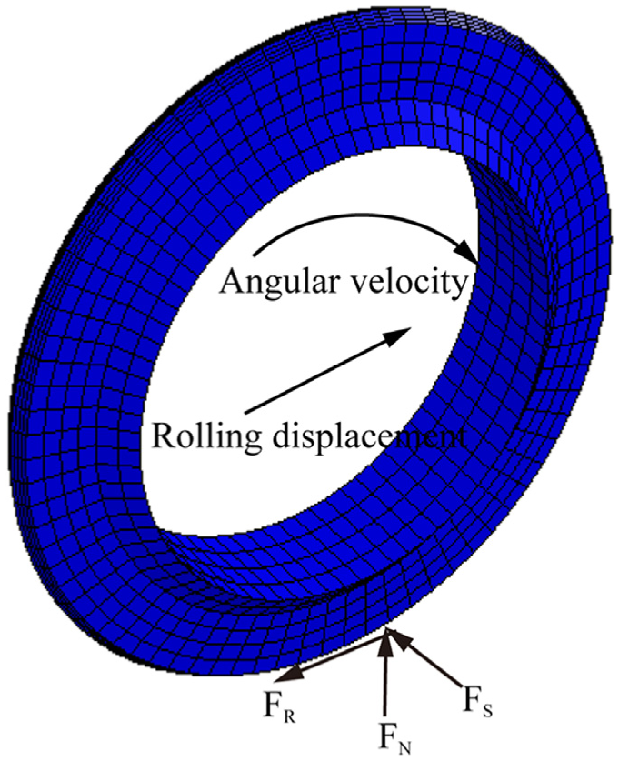
Normal force FN, the rolling force FR, and the side force FS acting on a disk cutter rotating with some angular velocity, resulting in some rolling displacement.
The various forces acting on the cutter with respect to time are shown in Figure 6. The damage region of the simulated rock sample and its cross section normal to the z-axis are shown in Figure 7. As can be seen from the simulation results, the rock sample initially experienced elastic deformation. With increasing cutting forces and penetration depth, plastic deformation was produced as the compressive stress exceeded the uniaxial compression strength. The damage appeared with the accumulation of plastic deformation, and a crushed zone under the disk cutter was formed. FN and FR gradually increased during this stage. The deformation of rock increased with increasing penetration depth, and simulation elements were removed from the simulation whenever the erosion criterion was satisfied. FN declined with the removal of elements. FS fluctuated about a value of zero over the entire simulated period. Owing to the nature of the other forces, the resultant force acting on the disk cutter varied in a manner largely equivalent to FN. Finally, the forces acting on the disk cutter stabilized and fluctuated about their respective average values after the penetration depth reached 7.6 mm (at 2 s), and their average values are given as 160.81 kN (FN), 18.60 kN (FR), and 7.71 kN (FS). The average resultant force is 163 kN.

Variation of the forces acting on the disk cutter with respect to time: (a) normal force (FN) versus time, (b) rolling force (FR) versus time, (c) side force (FS) versus time, and (d) resultant force versus time.

(a) Damage induced in the rock sample and (b) the damage in a cross section normal to the z-axis.
The forces acting on the disk cutter varied with respect to the penetration depth, and the results of the present simulation are compared with those obtained experimentally from LCM 4 in Figure 8 for penetration depths of 3.8, 5.1, 6.4, and 7.6 mm, respectively. The contact surface area increased with increasing penetration, resulting in correspondingly increased forces. The average values of FN derived from the simulation are in good agreement with the experiment values, FR is about 10% of FN, and the average values of FN and FR are slightly smaller than those of the experimental results.

Relationships between the forces acting on the disk cutter and penetration depth, as establish by the present simulations relative to those obtained experimentally from a linear cutting machine: 4 (a) the relationship between normal force (FN) and penetration depth, (b) the relationship between rolling force (FR) and penetration depth, and (c) the relationship between side force (FS) and penetration depth.
In the process of tunnel excavation, the strength of a compressed brittle rock strongly depends on the lateral confining pressure, where the rock compressive strength increases with increasing confining pressure. The peak stress and corresponding strain also increase. To illustrate the influence of confining pressure on the cutting forces, an equivalent confining pressure was applied to the free surfaces of the rock sample in the simulation at a penetration depth of 7.6 mm. The cutter forces obtained by simulation during the cutting process were, respectively, calculated for confining pressures of 10, 15, 20, 25, and 30 MPa, as shown in Figure 9. The values of FN are noticeably increased when exerting a confining pressure on the rock sample. The confining pressure not only increases the strength of the rock but can also transform the rock from a brittle material to a plastic material, such that FN becomes greater than that for an unconfined rock surface. However, no obvious change is observed for FR, indicating that the confining pressure has little influence on it. The value of FS fluctuated about zero, as shown in Figure 6(c), providing an average value much smaller than the other two force components. Therefore, the effect of confining pressure on this component was not considered.

Variations in the normal (FN) and rolling (FR) forces with respect to confining pressure.
Another factor that affected the rock strength is the temperature. In the process of tunnel excavation, the surrounding rock mass may experience a certain high temperature. The previous study shows that with the increase in temperature, the brittleness of rock is weakened and the ductility is strengthened. The peak strength is decreased. The cutter forces obtained by simulation were then, respectively, calculated for different temperatures of 25°C, 50°C, 75°C, 100°C, 125°C, and 150°C, as shown in Figure 10. The normal and rolling forces decreased with increasing temperatures. The result is in agreement with the literature. 43

Variations in the normal (FN) and rolling (FR) forces with different temperatures.
The rock is a rate-dependent material. Zhang and Zhao 44 described in detail the development and the state of the art in dynamic testing techniques and dynamic mechanical behavior of rock materials. When the strain rates of rock material changed with certain range from 10−5 to 101 s−1, there was little variation in the compressive strength. The strain rate of rock sample is in this range during the process of disk cutters breaking rock. So, the cutter forces changed with different strain rates are not simulated.
Rock fragmentation process for two disk cutters
Effect of cutter spacing on the rock fragmentation process
The s/p ratio for two disk cutters is an essential parameter in the cutting process, and an optimal value of s/p exists for each specific rock formation. The size of the rock sample employed in this simulation was equivalent to that employed in the previous section, and all other modeling parameters were unchanged. The finite element model employed for simulation of the two disk cutters was establish as shown in Figure 11. We assumed that the two disk cutters were installed in tandem, the first in the front and the second following by 220 mm. The obtained cross-sectional damage contours normal to the z-axis are shown in Figure 12 for the respective cutter spacing values of 51, 76, 100, and 120 mm. The damage area under each disk cutter exhibits a large overlap for a cutter spacing of 51 mm, whereas the damage region is disconnected when the cutter spacing is 120 mm. The red area represents the damage or fracture part of the rock sample. These are the chips during excavating tunnel. Reasonable cutter spacing values based on the simulation results are 76 and 100 mm.

Finite element model of the rock and two disk cutter systems.
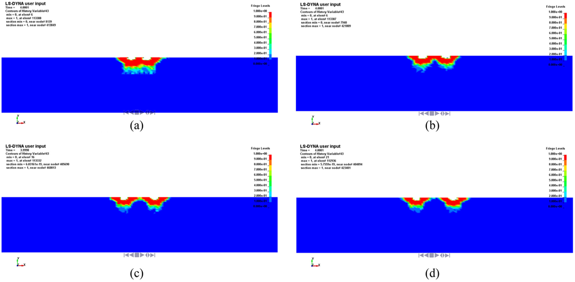
Damage contours normal to the z-axis for different cutter spacing values of (a) 51, (b) 76, (c) 100, and (d) 120 mm.
Values of the SE were obtained according to the numerical results with different s/p ratios, as shown in Figure 13, and are used to compare the relative cutting efficiency. A very narrow spacing initially results in a high SE for a given penetration. The value of SE decreases until a relative low level is reached. After that the spacing is further increased followed by an increasing SE. This indicates that the SE is minimal at a particular cutter spacing, and thus, cutting is optimal. 4

Relationship between the s/p ratio and the specific energy for the two disk cutters.
For penetration depths of 7.6 mm, the minimum SE value occurs at an s/p value of 10. The optimum values of s/p varied from 10 to15. For s/p ratios of 15 or greater, the damage region obtained by simulation existing between the cut traces was independent, leading to the formation of ridges. The results obtained from the present numerical modeling agreed well with those obtained during LCM testing. 4
Forces acting on the two disk cutters
The average values of FN and FR acting on the two disk cutters varied with cutter spacing, as shown in Figure 14. The average forces acting on the first cutter are greater than those acting on the second for spacing values of 51 and 76 mm (and, for FR, 100 mm as well). For FN, the average values on the two disk cutters differ by 1–3 kN, and the maximum value of which occurred at a cutter spacing of 76 mm. The average values of both FN and FR gradually reduced for spacing values greater than 76 mm and remained stable for spacing values of 120 and 140 mm. The different forces acting on the two tandem cutting disks for the more closely spaced configurations are owing to the fact that the first cutter causes some damage to the rock, and the relatively close spacing results in reduced forces acting on the second cutter. However, when the spacing exceeds a critical value, the cutting activities of the two cutters do not interact with each other, and the forces acting on the two cutters are equivalent.

Force variations with respect to cutter spacing: (a) average normal force (FN) with cutter spacing and (b) average rolling force (FR) with cutter spacing.
Conclusion
The previous studies are mainly focused on the 2D numerical modeling of the rock fragmentation based on the DEM and the FEM. The presented model was applied to simulate the fracture process with disk cutters by 3D FEM. A plastic damage material model for rock based on the extended Drucker–Prager strength criterion and the Johnson–Cook material model was proposed to describe the plastic compressive damage of rock-like material. The model was implemented into finite element software LS-DYNA. A finite element model comprising rock and a disk cutter was established to simulate the rock-cutting process. The presented model was applied to simulate the rock fracture process with disk cutters. The damage region of rock and cutting forces were obtained. The results accurately reflected the damage and failure process of rock and were in good agreement with LCM test results.
According to the simulation results, both the normal and the rolling forces fluctuated about average values that increased with increasing penetration depth. The side force fluctuated about a value of zero, which changed little with increasing penetration depth. The normal force exhibited an obvious increase under conditions of an applied confining pressure, whereas no significant change in the rolling force was observed.
The optimum s/p values determined during numerical modeling of two disk cutter systems agree well with those obtained during LCM testing. The optimum s/p values varied from 10 to 15. For s/p ratios of 15 or greater, the damage area existing between cut traces did not overlap, leading to the formation of ridges. The average normal and rolling forces acting on the first cutter are slightly greater than those acting on the second when the cutter spacing was relatively small.
Footnotes
Academic Editor: António Mendes Lopes
Declaration of conflicting interests
The author(s) declared no potential conflicts of interest with respect to the research, authorship, and/or publication of this article.
Funding
The author(s) disclosed receipt of the following financial support for the research, authorship, and/or publication of this article: This work was financially supported by the National Basic Research Program of China under grant no. 2013CB035402.