
Abstract
The fracture and fragmentation of rock materials are basic and important problem in geomechanics and blasting engineering. An approach, which can simulate the process of fracture and fragmentation of rock materials, is introduced in this work. A beam–particle model is first introduced in the frame of the discrete element method. In the beam–particle model, the neighboring elements are connected by beams. Consequently, a beam network is formed in the particle system. The strength characteristics of rock materials are reflected by the beam network. The strength criterion was then built to verify whether a beam exists or not. The process of rock fracture and fragmentation is described by the gradual disappearance of beams. Finally, two cases were presented to indicate the validity of the method proposed in this work.
Introduction
The fracture and fragmentation of rock materials are a current subject of keen interest, which are widely used in sciences and engineering, for example, mining exploitation, tunnel piercing, and protection works. At present, the numerical methods, which were used to simulate the fracture and fragmentation of rock materials, can be divided into two types: the method based on the continuum mechanics and the method based on multibody dynamics.
For the method based on the continuum mechanics, most simulations were completed by the finite element method (FEM) in which a constitutive relation and strength criterion need to be selected or constructed.1–3 However, the construction of the constitutive relation and strength criterion is difficult since the rock materials exhibit typically discontinuous, anisotropic, and heterogeneous characteristics. Therefore, the difference exists between the simulated and the experimental results. Otherwise, the flyrock, crack formation, and development are also difficult to be simulated by the method based on the continuum mechanics. The reason lies that the common nodes between the neighboring elements in the unmixed FEM would not be separated. Nevertheless, some researchers still tried to develop different types of mechanical models in the frame of FEM to break through the limitations of FEM such as the fictitious crack model (FCM), 4 the discrete cracking model (DCM), 5 the smeared cracking model (SCM),6,7 and the random lattice model (RLM). 8 The above-mentioned models are nonlinear fracture mechanics representation, which are general model to all kinds of materials. However, practical and numerical difficulties prevent its application in practical cases.
For the method based on multibody dynamics, the discrete element method (DEM) 9 was employed to simulate the fracture and fragmentation of rock materials since the fracture and fragmentation are the process from integrated state to granular state. The DEM, also called a distinct element method, is any of a family of numerical methods for computing the motion and effect of a large number of small particles. Although DEM is very closely related to molecular dynamics, the method is generally distinguished by its inclusion of rotational degrees of freedom as well as stateful contact and often complicated geometries. With advances in computing power and numerical algorithms for nearest neighbor sorting, it has become possible to numerically simulate millions of particles on a single processor. At present, DEM is becoming widely accepted as an effective method of addressing engineering problems in granular and discontinuous materials, especially in granular flows, powder mechanics, and rock mechanics. The DEM can realistically simulate the contacts, crush, and collisions between bodies.
A beam–particle model (BPM), which was proposed by Kun and Herrmann, 10 was employed to simulate the fracture and fragmentation of rock materials. In this work, the BPM proposed by Kun and Herrmann was extended to simulate three-dimensional problem. A beam network was first constructed to reflect the strength of the characteristics of rock materials. Then, the mechanical behaviors of beam network were described by the matrix displacement method (MDM).
Contact forces and particle motions
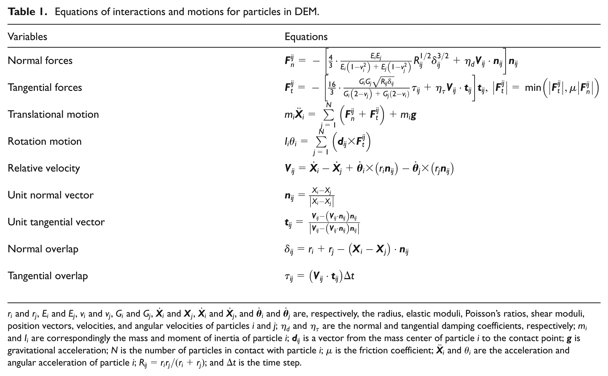
The simplified expressions of Mindlin’s theory11,12 are introduced to calculate the normal and tangential forces for two particles in contact with this study. The motions of particles are described by DEM. The equations of interactions and motions are listed in Table 1.13,14
Equations of interactions and motions for particles in DEM.
BPM
The simulated object is discretized into an assembly of particles in the BPM. In this work, the particle with spherical shape is used to discretize an object. The contact detection method 15 is first initiated to identify all neighboring particles for a particle. Then, a beam is added to connect arbitrarily two neighboring particles. As a result, a beam network is formed in the particle system. The strength of the material is reflected by the beam networks in BPM. The length of a beam is equal to the distance between two particles’ centers which lie at the beam ends. The beam cross section is supposed to be circular. The diameter of a beam cross section is determined as one-sixth of the beam length to ensure the requirement by Euler–Bernoulli beam theory. The interactions and motions of particles can be calculated by DEM. 9 Figure 1 shows a beam network in a particle system, and Figure 2 shows a deformed beam under the forces applied on the two ends of the beam.

Beam network in a particle system.
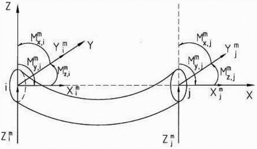
Schematic diagram of a deformed beam.
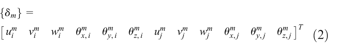
In the BPM, the deformation of a beam between two neighboring particles at a certain time is already known according to the DEM. Therefore, the end forces of a beam can be calculated by the MDM. 16 The forces and torque at the two ends of a beam can be expressed as

where
where

where
A beam would disappear only when the tensile strain and bend angle exceeds permissible value. Therefore, the fracture criterion 10 is
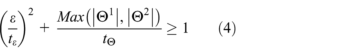
where
Two cases
Two cases were simulated to verify the validity of the method proposed in this work. The first case is to simulate a uniaxial compressive test of a rock specimen, and the second case is to simulate a blasting test of geotechnical medium with multilayers. In the two simulations, the specimens were generated by a seed expansion method (SEM). 17
The specimens used in the two simulations were generated by the SEM. 17 Seeds were first generated inside a given boundary, which include four spheres. The bases, which include three spheres, can be obtained by local Delaunay tessellation, which serve to generate new spheres by a simple algebraic calculation. This process is called as seed expansion. The distance function is employed to determine the distance between particles and boundaries. A refilling method has been developed in order to improve the packing density.
Simulation of uniaxial compressive test
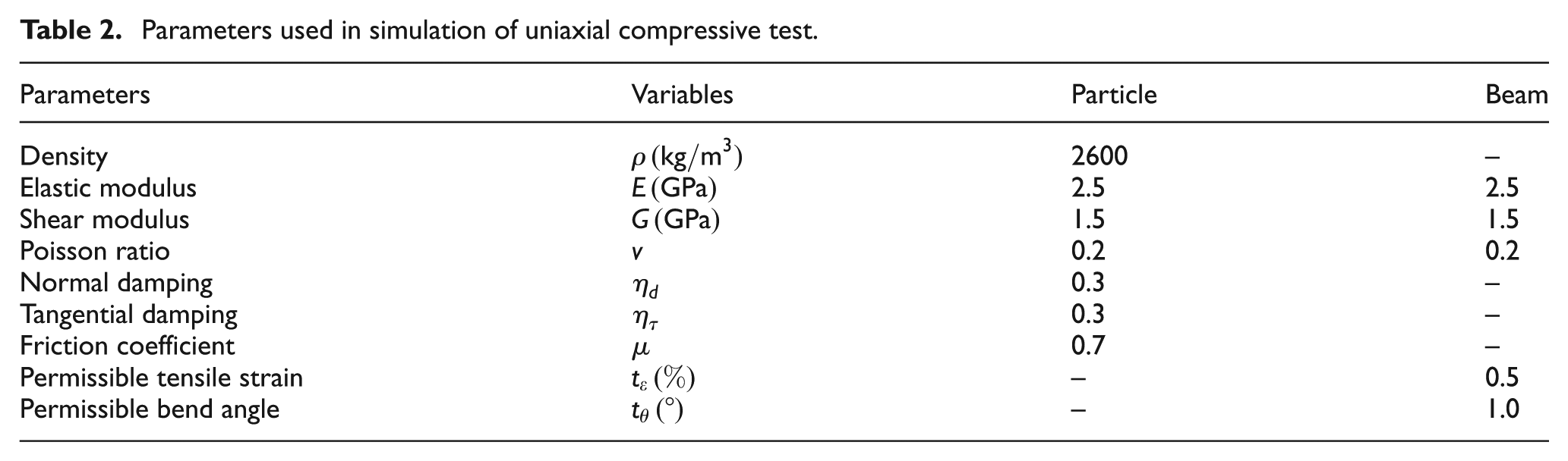
A uniaxial compressive test was simulated using the method proposed in this work. The pressure load, which was generated from a compression testing machine in a uniaxial compressive test, was applied in the simulation. The specimen generated by the SEM contains 21,432 spheres. The simulated parameters are listed in Table 2. The time step is 10−6s. It took 2 h or so to implement the simulation. The simulated results are shown in Figure 3. The comparison of uniaxial compressive curves from numerical simulation and experiment is shown in Figure 4. The simulated uniaxial compressive strength is approximately 10% less than that of experiment.
Parameters used in simulation of uniaxial compressive test.

Configurations of uniaxial compressive test for a rock specimen (specimen size: 50 mm × 100 mm).

Simulated and experimental uniaxial compressive curves.
Simulation of explosion in geotechnical media
To verify the validity of this method proposed in this work, a explosion in a geotechnical media was simulated. The specimen was also generated using the SEM. The specimen contains 405,672 spheres. For convenience, an empirical formula 18 is employed to describe the explosion pressure attenuation with time, that is

where
Comparison of the simulated and the explosion test results.


Simulated and practical result configurations for an explosion in a geotechnical media ((a) at 0.8 ms, (b) at 2 ms, (c) at 20 ms, and (d) photograph of the practical explosion result).
Discussion and conclusion
The BPM was developed in the frame of DEM in this work. A uniaxial compressive test and explosion in technical media were simulated using the method proposed in this work. The simulated results show that (1) the fracture and fragmentation can be well modeled by the BPM and (2) the phenomena of crack generation, crack developing, fragments formation, and fragments flying can also be reflected by the simulated results. Therefore, the BPM is suitable to simulate the process of fracture and fragmentation in which large deformation and rigid motions of specimen are involved. The method proposed in this work can break through some limitations of the methods based on the continuum mechanics when simulating large deformation and rigid motions.
Footnotes
Academic Editor: Chuanzeng Zhang
Declaration of conflicting interests
The authors declare that there is no conflict of interest.
Funding
This work was supported by the grant from the National Natural Science Foundation of China (no. 51174076). This grant is gratefully acknowledged.