
Abstract
Dynamic tension tests and compression tests were carried out for 5083-H111 aluminum alloy to investigate the dynamic mechanical behavior and its effect on energy absorption characteristics of an energy-absorbing device. The material constitutive relations were obtained at various levels of strain rates by means of tests. Three material models were performed on the energy-absorbing device of railway vehicles. We investigated the influence of the material dynamic behavior on the energy absorption capability. The results indicate that 5083-H111 aluminum alloy is endowed with negative strain rate sensitivity at medium–low strain rates and possesses the feature of negative and then positive strain rate sensitivity in the range of medium strain rates. The material presents obvious strain rate strengthening effect at high strain rates. Moreover, the order of magnitudes of the strain rate in the train collision is 0–2. It belongs to the medium strain rate. The practical absorbed energy of the structure made of 5083-H111 alloy is less than that of the same structure without regard to the strain rate effect in design phases.
Introduction
The aluminum alloy is one of the main materials used in the carbody structure of some subway trains and high-speed trains. All electric multiple units apart from CRH1 are made of aluminum alloys in China. The accidents of train collisions cannot be completely avoided by employing active safety measures. It is of great importance to investigate the crashworthiness of railway vehicles in China after the accident of China’s high-speed train crash shown in Figure 1. Large deformation of carbody structures may occur in the course of train collisions. The mechanical properties of aluminum alloys in plastic zone have a significant influence on the deformation and energy absorption of carbody structures.

Accident of the high-speed train collision in China.
In the studies of passive safety for trains, the strain rate effect of material is generally not considered in energy-absorbing structures.1–8 The Cowper–Symonds model is applied to describe the strain rate effect in steel carbody structures.9,10 A new type of energy-absorbing device for vehicles is studied based on the Johnson–Cook model.11,12 It is generally acknowledged that the aluminum alloy is not sensitive to strain rates. The flow stress of aluminum alloys, such as 6060 and 6082, is almost not sensitive to strain rates at high strain rates, and the 7000 series aluminum alloys possess moderate strain rate sensitivity.13,14 High strength damping aluminum alloys and pure aluminum L2 possess significant strain rate sensitivity.15–17 However, casting aluminum alloys, high temperature damping aluminum alloys, and Al/Li alloys are endowed with particular strain rate weakening effect, which is called negative strain rate sensitivity.18,19 Negative strain rate sensitivity is also found for some alloys in the 5000 series at strain rates below 1 s−1.20–23 Unlike the normal strain rate sensitivity of steel, the flow stress decreases with the increasing strain rates due to the negative strain rate sensitivity. Different ingredient proportions of aluminum alloys may cause significant differences in material properties. Therefore, it is very necessary to investigate the dynamic mechanical behavior of aluminum alloys of railway vehicles.
The train collision is a process of dynamic deformation. Different parts of structures exhibit different stresses and strain rates, which change with time. The dynamic responses of carbody structures are mostly in the range of medium strain rates since the velocities of most train collision accidents are not very high. 10 Some researchers consider the strain rate effect by using existing constitutive models, but the parameters of the models are almost based on experiences. The dynamic behavior of metal materials is investigated at a wide range of strain rates by many researchers.13–22 However, the strain rates are too low or too high for aluminum alloys. The results are not suitable for the analysis of train collisions. Moreover, the strain rate sensitivity of 5083-H111 alloy is unclear at medium strain rates (1–102 s−1), which is important for the study of train collisions. This article focuses on the dynamic mechanical behavior of 5083-H111 aluminum alloy used in carbodies of Chinese high-speed trains. We especially pay attention to the strain rate sensitivity at the medium strain rate. Dynamic tension and compression tests are conducted on the alloy at room temperature. We obtain the stress–strain curves at strain rates of different orders of magnitude by means of impact tests. The dynamic mechanical behavior of the material is shown at a wide range of strain rates. Finally, we analyze the influence of the material dynamic behavior on the energy capacity of an energy-absorbing device.
The remainder of this article is organized as follows: section “Material and methods” presents the material and testing methods in detail. Testing results and discussion are represented in section “Results and discussion.” Section “Analysis of energy-absorbing devices in head cars” describes the influence of the material dynamic mechanical behavior on the energy capacity. Finally, the concluding remarks are presented in section “Conclusion.”
Material and methods
The 5083-H111 aluminum alloy is used as the test material. The aluminum alloy is endowed with good properties of corrosion resistance and welding. The main chemical components are listed in Table 1. All the specimens are made of the same raw material.
Components of 5083-H111 aluminum alloy.

The specimens of the static tests and the dynamic tension tests are the plates of dumbbell shape. The size of the specimen is shown in Figure 2. The quasi-static test is carried out with a MTS machine. The dynamic tension tests of medium strain rates are conducted with a INSTRON testing machine. The medium strain rate region ranges from 1 to 102 s−1. All the specimens of dumbbell shape are pulled until fracture takes place.

Specimen of dumbbell shape plate.
The specimens of dynamic compression tests are the cylinder with the size of Φ10 mm × 8 mm. The high strain rate is generally larger than 103 s−1. The tests of high strain rates are implemented on the split Hopkinson pressure bar (SHPB) testing device which is shown in Figure 3. The diagram of fundamental principle of the SHPB system is depicted in Figure 4. The SHPB device consists of the striker, input bar, specimen, output bar, absorbing bar, bumper, high dynamic strain instrument, computer, and so on. The diameters of the striker, input bar, and output bar are equal to 14.5 mm. The lengths of the striker, input bar, and output bar are 200, 400, and 525 mm, respectively. The velocity of the striker is controlled by the pressure of an air gun. So, the velocity of every test is an approximate value. The basic principle of the SHPB is described as follows. The striker impacts the input bar at a high velocity. The elastic stress wave which is also called the incident wave generates in the input bar. The incident wave is recorded by the strain gage on the input bar. Afterward, part of the incident wave is reflected when it reaches the interface between the input bar and the specimen. The reflected wave is gauged by the strain gage on the input bar again. Moreover, the transmitted wave which passes through the specimen is measured by the strain gage on the output bar. The high dynamic strain instrument records the signals of the incident wave, the reflected wave, and the transmitted wave. According to the theory of one-dimensional wave propagation, we can obtain the strain rate, average strain, and average stress of the specimen. The equations based on the assumption of homogeneity are given as follows 24

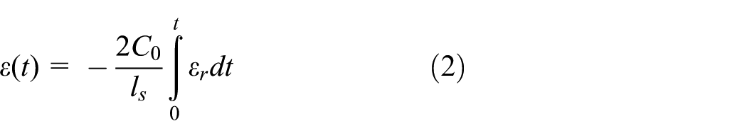
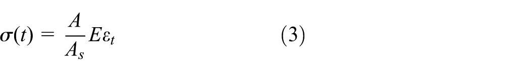
where t,

Split Hopkinson pressure bar (SHPB) testing device.

Schematic diagram of the split Hopkinson pressure bar (SHPB) system.
Results and discussion
The static curve of true stress versus true strain obtained with the MTS machine is used to compare the results of the dynamic tension and compression tests. Several dynamic tests at approximately identical strain rates are conducted to acquire the curve which is more reasonable.
Results of dynamic tension tests
Several dynamic tension tests are carried out at the strain rate of 5, 10, 100, and 400 s−1. The true stress versus true strain curves are shown in Figure 5, which also depicts the static stress–strain curve. The figure shows that the yield stresses of these curves are all approximately equal to 150 MPa. The failure strain increases with the strain rate. It is worth mentioning that the curves of the strain rates of 5, 10, and 100 s−1 are lower than the static curve. The flow stresses are less than that of the static curve at the same strain. The phenomenon is known as the negative strain rate sensitivity. The curve of the dynamic tension test exhibits the trend of getting close to the static curve as the strain rate increases to 400 s−1.
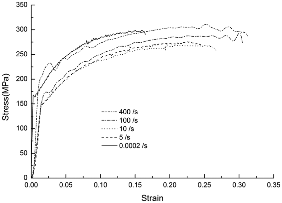
True stress versus true strain curves of the dynamic tension tests.
In order to verify the reliability of the above tests, two other tension tests are conducted repeatedly at the strain rate of 10 s−1. The results are shown in Figure 6. The true stress versus true strain curves are still lower than the static curve. In conclusion, the dynamic curve is lower than the static curve for 5083-H111 aluminum alloy when the strain rate is lower than a certain value. The dynamic curve may get close to the static curve or exceed it as the strain rate increases. Consequently, the 5083-H111 alloy possesses the strain rate weakening effect (negative strain rate sensitivity) at medium–low strain rates. It is endowed with the feature of negative and then positive strain rate sensitivity in the range of medium strain rates.

Verification of the dynamic tension tests.
Results of dynamic compression tests
The dynamic compression tests are conducted at high strain rates using the SHPB testing device. The specimens of the same size generate different results at different impact velocities. The strain rates are 1064 and 1171 s−1, respectively, when the velocity of the striker is 20.6 m/s. The corresponding strain rate is 2317 s−1 at the velocity of about 23.5 m/s. The testing results are shown in Figure 7. The static curve is also depicted in Figure 7 as a reference. The yield stresses of the dynamic compression tests approximately increase to 200 MPa at the high strain rates, which is greater than the static yield stress. The failure strain at the strain rate of 2317 s−1 is greater than that of the strain rate of 1171 s−1. In addition, the ultimate strength of the former is also greater than that of the latter. The flow stresses of high strain rates are greater than the corresponding value of the static result at the same strain. So, 5083-H111 aluminum alloy possesses the strain rate strengthening effect at high strain rates, which is also called the positive strain rate sensitivity.

True stress versus true strain curves of the dynamic compression tests.
Discussion of dynamic constitutive relations
The Cowper–Symonds model 25 and the Johnson–Cook model12,22 are two classical models in which the strain rate effect is considered. The equations of the models are expressed as follows

where σf and σs are the flow stress and the quasi-static yield stress, respectively; εe and n represent the effective plastic strain and the strain hardening exponent; β and EP are the coefficients with respect to strain hardening; and C and P denote the material parameters of strain rate hardening.
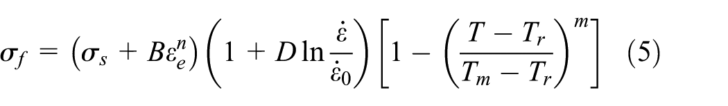
where σf and σs are the flow stress and the static yield stress; εe, B, and n are the effective plastic strain, the strain hardening coefficient, and the strain hardening exponent, respectively; D denotes the coefficient with respect to strain rate effect;
The strain rate effect term in the Cowper–Symonds model is only related to the material parameters C and P. This model is usually applied to describe the strain rate strengthening effect. However, it is not applicable for describing the negative strain rate sensitivity. The Johnson–Cook model can be utilized to represent the strain rate sensitivity of metals at low and high strain rates. It can also be used to describe the negative strain rate sensitivity when the material parameter D is negative. However, when it comes to the characteristic of negative and then positive strain rate sensitivity in the range of medium strain rates, the Johnson–Cook model is not applicative. 22 Consequently, the Cowper–Symonds model and Johnson–Cook model are not employed in the simulation of energy-absorbing structure. Modified constitutive relations cannot be approached immediately for the 5083-H111 aluminum alloy in the software LS-DYNA.
In order to describe the special characteristic of 5083-H111 aluminum alloy accurately, a table interpolation method (TIM) is used in this article. The TIM is widely used in nonlinear finite element softwares. All data of the stress versus strain curves are listed in a table. Each curve is provided with a corresponding strain rate. The curve of other strain rates can be acquired by smooth interpolation from adjacent curves. Then, the stress for the corresponding strain can be acquired at a certain strain rate in this way. It is generally recognized that the relation between the flow stress and the strain rate is the exponential relationship or the logarithmic relationship. The stress–strain curves at strain rates of every order of magnitude have been given in this article. As a result, this kind of interpolation can achieve a certain precision. Higher precision can be obtained if more stress–strain curves of other strain rates are provided. The special trend of material constitutive relations has no effect on the TIM. Any particular strain rate effect can be described by the TIM as long as there are enough test curves at different strain rates.
Analysis of energy-absorbing devices in head cars
The strain rate only affects the carbody structure where severe plastic deformation occurs in train collisions. It has no influence on the material property of most carbody structures where only small elastic deformation takes place. So, the strain rate status of train collisions can be represented by that of the energy-absorbing structure of the carbody. Assuming that there is no material failure in the simulation of train collisions, most of the dissipative energy is absorbed by the coupler and the energy-absorbing structure. As a result, we only need to consider the strain rate effect in the energy-absorbing structure, and the strain rate effect can be neglected in other parts of the carbody structure.
A rigid-flexible vehicle model is built and simulated in the software LS-DYNA. The energy-absorbing structure is considered as an elastic–plastic body, and other parts of the vehicle are considered as rigid bodies. The elastic–plastic body and the rigid bodies are coupled rigidly. The vehicle model is shown in Figure 8. Since the main object is the energy-absorbing structure, the rigid-flexible vehicle model can be utilized to crash with a rigid wall at a constant velocity. We investigate the characteristic of the energy-absorbing structure and the influence of the material dynamic mechanical behavior on the energy absorption capacity of the energy-absorbing structure. The energy-absorbing device is composed of a bolted mounting plate, an anti-climbing plate, and three energy-absorbing tubes. Figure 9 shows the model of the energy-absorbing device and five points monitoring the strain rate status. The geometrical sizes of the tube are shown in Figure 9(b), and the distance between two adjacent tubes is 180 mm. The length of the energy-absorbing tube of the device is 400 mm. The effective length of energy absorption is 300 mm in terms of the rule that the compression travel is recommended as 75% of the total length. The LS-DYNA is employed as the simulation tool. Shell elements of Belytschko–Tsay type are used in the finite element model. The anti-climbing plate is discretized with solid elements. In addition, the self-contact and the surface-to-surface contact are applied in the simulation model. The generalized Von Mises yield criterion is utilized in the model. Moreover, the vehicle mass is 60 t, and the collision velocity is 36 km/h.
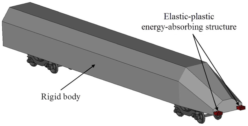
Rigid-flexible vehicle model.
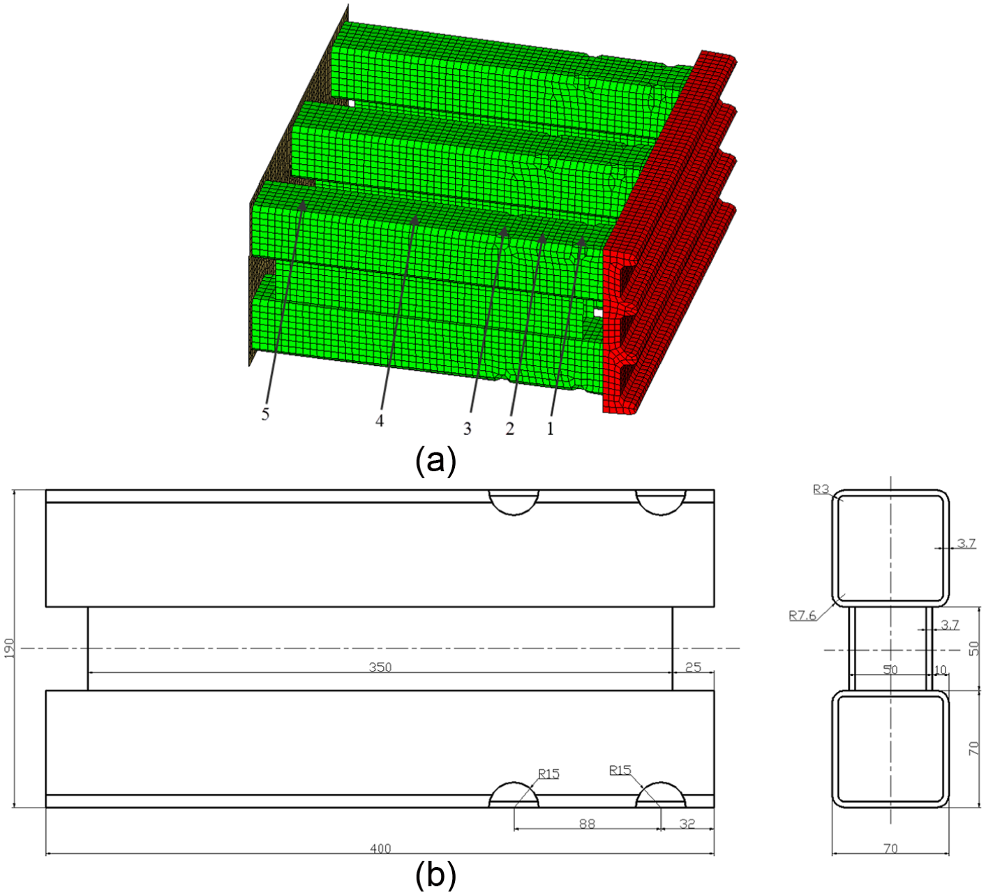
Energy-absorbing device: (a) finite element model and (b) geometrical size of the tube.
Three material models are considered in the vehicle model. The first model is a bilinear plastic hardening model. The second one is a piecewise linear elastic–plastic model. The third one is the piecewise linear elastic–plastic model which describes the strain rate effect by means of the TIM. The material models are listed in Table 2. The density, Young’s elastic modulus, Poisson’s ratio, and yield stress of the three models are 2700 kg/m3, 69,000 MPa, 0.33, and 150 MPa respectively. The strain rate effect is ignored in the first two models. The tangent modulus of the bilinear plastic hardening model is set as 1000 MPa according to the test results. The static stress–strain curve shown in Figure 5 is employed in the second model. The selected values of the static stress–strain curve are given in Table 3. Moreover, the values of required parameters of the third model are also listed in Table 3.
Material models.

TIM: table interpolation method.
Parameters of the material models 2 and 3.

The results of the three models are shown in Figures 10–13. Figure 10 shows the strain rate time history of the five marked points. It is obvious that the strain rate changes with time irregularly. High peaks occur at the initial stage. Then, the wave decreases and shows high-frequency oscillations at the metaphase stage. They decrease to zero at last. The phenomenon is the same as the strain rate time history of metal material in SHPB tests. The average strain rate is low when the monitoring point is far from the crashing interface. In addition, the order of magnitude of the strain rate ranges from 0 to 2, which belongs to medium strain rates. Figure 11 depicts the interfacial forces of the three material models. The forces oscillate with the increasing displacement. The minimum values of the three interfacial force curves are approximately equal, but they do not appear at the same position. The ascending order of the maximum interfacial forces of the three models is: model 1, model 3, and model 2. The final deformation shape of the three models is shown in Figure 12. The final shape of the first model is unstable. On the contrary, the deformation of the last two models is stable. The number of plastic hinges of the first model is less than that of the other two models. The absorbed energy of the three models is illustrated in Figure 13. The order of the absorbed energy is the same as that of the maximum interfacial forces. The absorbed energy of model 3 is 7.05% less than that of model 2.
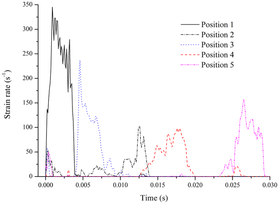
Time history of strain rates.

Comparisons of interfacial forces of three material models.
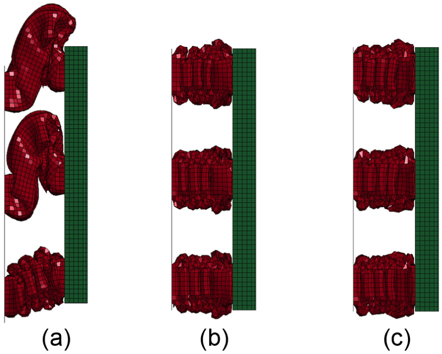
Final deformation shape of three material models: (a) model 1, (b) model 2, and (c) model 3.

Comparisons of the absorbed energy of three material models.
The average interfacial force and the absorbed energy of the model 1 are the smallest on account of the unstable deformation which is generated by insufficient folded deformations in the collision. The interfacial force of the first model is low because off-center deformation occurs in two energy-absorbing tubes. The peak values of every force–displacement curve represent the initial formation of plastic hinges. The valley values of every force–displacement curve imply the final stage of plastic hinges. Due to the special characteristic of 5083-H111 aluminum alloy at medium strain rates, the absorbed energy of the model 3 which considers strain rate effect is less than that of the same model which ignores strain rate effect. That is to say, the designed energy capacity calculated with material models which ignore strain rate effect is greater than the practical energy capacity. Because the special strain rate effect exists in the 5083-H111 alloy in actual collisions, a lot of design of energy-absorbing structures is generally based on static material properties. Consequently, we suggest that at least 10% of the nominal energy capacity should be increased in the design of the energy-absorbing structure made of the 5083-H111 alloy according to the special dynamic mechanical behavior.
Conclusion
We study the dynamic mechanical behavior of 5083-H111 aluminum alloy at medium–low and high strain rates in this article. Some particular phenomena are found through dynamic tension and compression tests. In addition, we also investigate the influence of strain rate effect on the energy absorption characteristic of a certain energy-absorbing structure. The results manifest that the stress–strain curves of 5083-H111 aluminum alloy obtained with the dynamic tension tests are lower than the static stress–strain curve at medium strain rates. But the dynamic curve gets close to the static one with the increasing strain rates. The material possesses the negative strain rate sensitivity at medium–low strain rates. It is endowed with the feature of negative and then positive strain rate sensitivity in the range of medium strain rates. The yield stress and the flow stress of the aluminum alloy are greater than those of the static result in the dynamic compression tests. The material performs strain rate strengthening effect at high strain rates. Furthermore, the strain rates of the energy-absorbing structure are in the range of medium strain rates, and the order of magnitude of the strain rate ranges from 0 to 2. Owing to the special characteristic of 5083-H111 aluminum alloy at medium strain rates, the practical absorbed energy of the energy-absorbing structure is less than that of the same structure ignoring strain rate effect in design phases.
Footnotes
Acknowledgements
The authors would like to thank the editor and reviewers for their valuable comments and suggestions.
Academic Editor: Crinela Pislaru
Declaration of conflicting interests
The author(s) declared no potential conflicts of interest with respect to the research, authorship, and/or publication of this article.
Funding
The author(s) disclosed receipt of the following financial support for the research, authorship, and/or publication of this article: This work was supported by the National Natural Science Foundation of China (51275432, 51405402, and 51505390) and the Independent Research Project of TPL (2014TPL_T04).