
Abstract
In the field of modern large-scale telescope, primary mirror supporting system technology faces the difficulties of theoretically uniform output force request and bias compensation. Therefore, a novel position control system combining hydraulic system with servo motor system is introduced. The novel system ensures uniform output force on supporting points without complicating the mechanical structure. The structures of both primary mirror supporting system and novel position system are described. Then, the mathematical model of novel position control system is derived for controller selection. A proportional–derivative controller is adopted for simulations and experiments of step response and triangle path tracking. The results show that proportional–derivative controller guarantees the system with micrometer-level positioning ability. A modified proportional–derivative controller is utilized to promote system behavior with faster response overshoot. The novel position control system is then applied on primary mirror supporting system. Coupling effect is observed among actuator partitions, and relocation of virtual pivot supporting point is chosen as the decoupling measurement. The position keeping ability of the primary mirror supporting system is verified by rotating the mirror cell at a considerably high rate. The experiment results show that the decoupled system performs better with smaller bias and shorter recovery time.
Keywords
Introduction
Modern telescopes are always designed with larger primary mirrors, which enable astronomers to explore further universe plants with higher image quality. No doubt that as the primary mirror diameter becomes lager, a number of challenges occur in telescope technology, and primary mirror supporting technology will be one of them.1,2 Primary mirror supporting system (PMSS) bears the primary mirror weight and controls the mirror attitude toward telescope mirror cell, without causing excessive surface deformation on primary mirror. The PMSS design should follow two basic principles to guarantee telescope imaging quality: First, the output force of all supporting actuators must be theoretically equal to avoid large deformation on mirror surface, although the active supporting system will adjust the output force in detail; second, the supporting system must be able to compensate the relative position bias between the primary mirror and mirror cell, namely, the supporting system must be a position control system.
For small-scale and middle-scale telescopes, 9-point Grubb supporting systems are always adopted to generate theoretically uniform output force. A spherical hinge and a triangular support plane are utilized to balance internal counterforce among supporting points of the same partition. As the telescope becomes larger, 118-point-Hindle supporting system becomes an alternative choice. This supporting system provides more supporting points and guarantees the primary mirror with less surface deformation. Such supporting systems are so-called mechanical whiffletree supporting system, and the supporting points can be increased to as many as 54 points if needed. Despite providing uniform force, these multilevel supporting systems bear complicated mechanical structures, and they do have a strict upper limit of supporting points. Above all, the displacement bias between mirror cell and primary mirror cannot be compensated on mechanical whiffletree supporting system.
Traditional position control system mainly comprises electro-hydraulic servo systems (EHSS) and servo motor systems (SMS). EHSS always include oil source, servo valve, and hydraulic cylinder or motor, and servo valve ensures precise position control of EHSS. As an alternative option for position control, EHSS have advantages such as high power-to-weight ratio, good compliance to payload capability, and high immunity to wear. Yet EHSS exhibit significantly high nonlinearities in their dynamic behavior due to fluid compressibility and complex flow properties of servo valves. Researchers have made great efforts to overcome the nonlinearities of EHSS. These measurements include immune proportional–integral–derivative (PID) control, 3 adaptive robust control based on wavelet neural network technology, 4 adaptive fuzzy sliding mode control, 5 output feedback control, 6 real-time control based on a neurobiologically motivated algorithm, 7 adaptive controller design algorithm with external disturbances, 8 and tracking error–based adaptive control. 9 Eliminating the negative effects of nonlinearity, EHSS play an important part on modern position control system. Nevertheless, EHSS do not perform excellent enough on micrometer-scale position control system. Besides, periodic interference of hydraulic pump and unavoidable fluid leakage of hydraulic component make it harder to apply EHSS on precise optical instruments. As an alternative choice for precise position control, SMS include amplifier, servo motor, and screw to realize linear movement. Plenty of researches have been performed to promote the positioning ability of SMS, mainly focusing on controller design and optimization of controller parameters. Such controller design includes L2 robust control, 10 friction compensation based on a genetic algorithm, 11 active disturbance rejection control, 12 sensorless control using Kalman filter, 13 reduced-order observer design, 14 and sliding mode control. 15 Optimization of controller parameters includes fuzzy controller optimization based on adaptive gravitational search, 16 PID controller tuning with a genetic algorithm, 17 and PID controller tuning using a bat algorithm.18,19 Hence, SMS show excellent positioning behavior with either classical controller or advanced control technology and seem to be a suitable solution for PMSS. Nevertheless, SMS do not show good compliance to payload capability as EHSS do, which make it difficult to generate uniform output force on supporting points.
To meet the demand, a novel position control system (NPCS) combining the good compliance of EHSS and the precise position ability of SMS is proposed. This system utilizes an amplifier and a servo motor to control the output displacement of a hydraulic amplifying cylinder. Then, based on the principle of communicating vessels, the system converts the amplifying cylinder displacement into micrometer-scale displacement of supporting points with uniform output force. The rest of this article is organized as follows: section “System description” presents the entire structure and kinematic behavior of the PMSS and basic structure of the NPCS. Mathematical model of the position control system is constructed in section “Mathematical model of NPCS.” Then, controller design based on mathematical model and relevant experiments are carried out in section “Controller design, simulations, and experiments of NPCS.” Section “Position keeping experiment of PMSS” verifies the practicability of the NPCS on PMSS. Finally, conclusions are provided in section “Conclusion.”
System description
General structure of PMSS
General structure of the platform is shown in Figure 1. The prior purpose of the PMSS is to generate uniform output force on supporting points. The mirror cell is installed on a swivel table (not shown in the figures), and when the mirror cell inclines, gravity distribution will change, and such position bias between primary mirror and mirror cell will occur. So, the subsequent purpose of the PMSS is to compensate the bias.

General structure of PMSS.
The supporting points of primary mirror are divided into three partitions, and the locations of all supporting points are specifically optimized to control the surface deformation of primary mirror. The number of supporting points in a partition is three. Also, if the primary mirror becomes larger, it can be extended without complicating the structure of PMSS. As shown in Figure 1, the working hydraulic chambers in the same partition are parallel connected with each other and then the supporting cylinders in the same partition work based on the principle of communicating vessels, which ensures the uniform output force of supporting points. Due to the fluidity of hydraulic oil, the supporting cylinders in the same partition will automatically adjust their output displacement according to the primary mirror attitude. Specifically, the supporting cylinders in the same partition provide a virtual pivot supporting point on the primary mirror. Output displacements of three partitions determine the attitude of the primary mirror, and each partition contains an oil control unit and three or more supporting cylinders. To compensate the bias between mirror and cell, each partition works as an electro-hydraulic position control system.
Kinematic analysis of PMSS
As mentioned above, all the supporting points of a partition provide a virtual pivot supporting point on the primary mirror. Then, the primary mirror can be regarded as a moving plane supported by three parallel homologous electro-hydraulic actuators. Figure 2 depicts the schematic configuration of the 3-degree-of-freedom (DOF) electro-hydraulic parallel mirror. Moreover, two Cartesian coordinate systems are also added to PMSS, and {B} coordinate system is the body coordinate system fixed to the moving primary mirror, while {C} coordinate system is the base coordinate system fixed to the mirror cell.

Schematic configuration and coordinate systems of PMSS.
All the actuators movements conduct along the Z-axis of {C} coordinate system. The kinematic pair between partition 1 and primary mirror is a Hooke joint which allows rotation around the X-axis and Y-axis of {C} coordinate system but no rotation around the Z-axis of {C} coordinate system. The kinematic pair between partition 2 and primary mirror is a spherical joint plus a plane joint which allow the contact point to move parallel to the X-Y plane of {B} coordinate system. The kinematic pair between partition 3 and primary mirror is the same as that of partition 2. Consequently, the primary mirror can only conduct three motions: linear motion along the Z-axis and angular motions around the X-axis and Y-axis of {C} coordinate system, denoted as heave (q1), pitch (q2), and yaw (q3), respectively. The ith partition actuator length is denoted as li (i = 1, 2, 3), and according to the basic geometry locating principle, the primary mirror attitude is entirely determined by li.
Three position sensors are installed on the location of virtual pivot supporting point, attached to the mirror cell (Figure 1, linear variable differential transformer (LVDT)). These position sensors monitor the position bias between the primary mirror and mirror cell. To compensate the bias, the displacement of each partition actuator can be described as
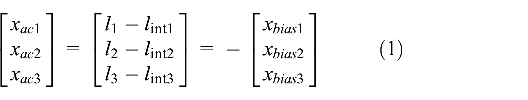
xbiasi is the position bias of ith partition.
Description of the NPCS
Figure 3 shows the schematic diagram of an actuator partition position control system. The supporting cylinders are installed on the mirror cell, and each rod of supporting cylinders is attached to the upper platform using an interface device which allows the contact point to move parallel to the primary mirror. The output displacement of all supporting cylinders is presented as one supporting cylinder output displacement in Figure 3. Then, the NPCS includes a DC motor, a screw, an amplifying cylinder with small effective area, a supporting cylinder with large effective area, an accumulator, and two transmission pipes, as illustrated in Figure 3.

Basic hardware configurations of NPCS.
In this supporting system, the primary mirror attitude toward mirror cell is determined by the displacement of supporting cylinders of three NPCSs. The large effective area ratio between the supporting cylinder and the amplifying cylinder assures the supporting system with micrometer-level positioning accuracy. The screw converts the DC motor rotation into the amplifying cylinder translation, thereby determining the flow direction between the working chambers V1 and V2. The accumulator provides the NPCS with a steady working pressure.
Some sensors are installed in this system to monitor these hardware configurations, which include the following:
P2: pressure sensor of the supporting cylinder of lower chamber;
P3: pressure sensor of the supporting cylinder of upper chamber;
Ω: angular speed sensor of the DC motor;
Xv: magneto telescopic position sensor of the amplifying cylinder;
Xp: LVDT position sensor of the supporting cylinder;
T: temperature sensor of the supporting cylinder.
Based on the hardware configurations, the single-input and single-output (SISO) position control system is depicted in Figure 4. In this system, the supporting cylinder displacement Xp is the control target. The desired position is predesigned and compared to the position feedback signal. Through controller action, the DC motor produces reasonable rotation and then decides the motion of the amplifying cylinder and thereby changes the supporting cylinder displacement by hydraulic fluid transmission.

Schematic diagram of NPCS control.
To obtain superior performance, nonleakage and frictionless supporting cylinder has been designed so far Li. 20 The idea of nonleakage design makes it possible to apply hydraulic system on PMSS. In order to choose a practicable controller, the mathematical model of NPCS will be constructed in the following section.
Mathematical model of NPCS
NPCS is the crucial subsystem of PMSS. The servo motor controls the converting cylinder movement and thereby decides the flow direction of oil filled between the imposed chamber of the converting cylinder and the lower chambers of the supporting cylinders. An accumulator fulfilled with pressured nitrogen is connected with upper chambers of the hydraulic cylinders, and this measurement declines dramatic pressure fluctuation. The displacement of supporting cylinder piston is determined by both chambers and influenced by the load. The model of actuator partition shown is introduced in this section, and for feasibility and simplification, several following assumptions are made:
One actuator partition contains only one supporting cylinder, and the external load is simplified as an inertia load;
All mechanical components in the actuator partition are rigidly connected;
Neglect the pipe effect between the accumulator and the upper chamber of the supporting cylinder and consider the pressure changing procedure inside the accumulator as a constant temperature procedure;
Neglect the pipe effect between the converting cylinder and the lower chamber of the supporting cylinder.
A simplified schematic diagram is depicted in Figure 4. The system can be divided into a hydraulic subsystem and an electromechanical subsystem.
Hydraulic subsystem modeling
The hydraulic subsystem transforms the displacement from converting cylinder to supporting cylinder. Applying the law of continuity to each chamber, the load flow continuity equations are given as equations (2)–(5)


According to assumptions (2) and (4), we obtain

Then, equations (2)–(5) can be simplified as

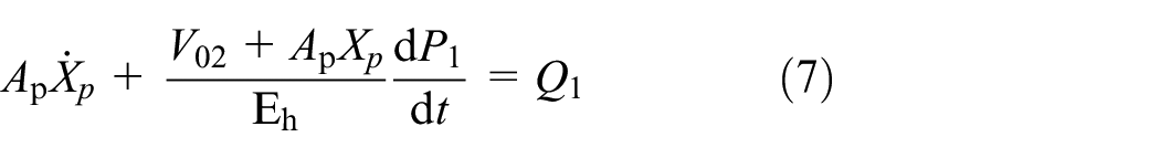
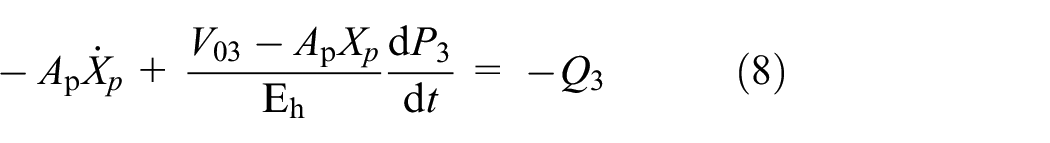

Combining equations (6) and (7), we obtain

State equation of nitrogen in the accumulator can be described as
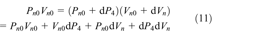
where Pn0 and Vn0 are the initial pressure and volume of nitrogen in the accumulator, respectively. Note that

Then, from equation (11), we obtain

Combining equations (8), (9), and (12), we obtain

Since the system works at low pressure ranging from 2 to 5 bar, we can easily obtain
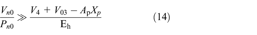
Then, equation (14) can be simplified as

By applying Newton’s second law, the supporting cylinder’s force balance equation is

Combining equations (10), (15), and (16) and proceeding Laplace transform, we obtain


From the above equations, the transfer function from converting cylinder displacement to supporting cylinder displacement can be depicted as

Electromechanical subsystem modeling
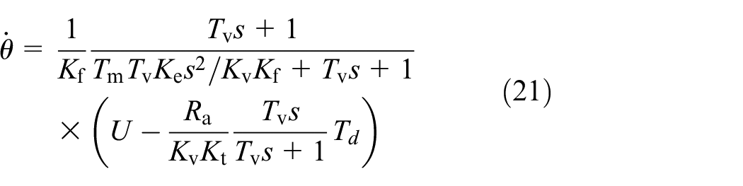
The electromechanical subsystem converts the voltage from controller to converting cylinder displacement. Compared to mechanical components, amplifier has high response frequency. For the selected amplifier and servo motor, the relationship of motor output velocity, input voltage, and load torque can be depicted as
Applying Newton’s second law to converting cylinder, the force balance equation is

Change equation (19) to Laplace form, then we obtain

A screw is utilized to change motor rotation to cylinder translation, and the relationship can be described as


From equations (21) to (25), the transfer function from control voltage to converting cylinder displacement can be depicted as

NPCS modeling discussion
To sum up, the hydraulic subsystem can be described as a second-order system, and the electromechanical subsystem can be described as a second-order system with an integral. For most occasions, such electromechanical subsystem can be simplified as a first-order system with an integral. Then, the NPCS can be regarded as third-order system with an integral. This electro-hydraulic position control system avoids the nonlinearity of hydraulic valves, and it works at a small range of displacement with high positioning precision, so it is reasonable to linearize the system model as above. Practicable controllers will be adopted in the following section to realize micrometer-scale position control of NPCS.
Controller design, simulations, and experiments of NPCS
Environment description
Nowadays, adaptive and robust controllers are often used to achieve better performance for hydraulic actuators. However, such controllers always require measurements of actuators’ velocity and hydraulic pressure in addition to actuators’ position, and it might be difficult to obtain these signals in real time. 21 Besides, these controllers are always suffering with two major problems: limited accessibility for online calibration and heavy computational load, which cause great difficulties in implementation. Classical and modified proportional–derivative (PD) control technologies are widely used. 22 They are easy to implement and always show excellent behaviors, especially for low-order systems.23–26 Thereby, classical PD controllers’ performance of NPCS will be verified by mathematical simulations and experiments in this section.
For the simulation parts, NPCS mathematical model is constructed by MATLAB or Simulink programming according to the linearization procedure in section “Mathematical model of NPCS,” and the sampling time is set to 1 ms. The hydraulic oil properties such as oil bulk modulus and oil viscosity are set with constant values.
The control performance experiment is carried out on an NPCS test rig, which is partly shown in Figure 5. The NPCS test rig features (1) one supporting cylinder, (2) one converting cylinder, (3) one servo motor, (4) one accumulator, (5) digital-to-analog (D/A) PMAC DTB-28B board, (6) analog-to-digital (A/D) PMAC ACC-8B board, (7) signal converter and amplifier, (8) position and pressure transducers, (9) a real-time PMAC controller board, and (10) a personal computer (PC) for human–computer communication and test rig state detection. The control program of the NPCS is programmed in advance and then downloaded to the real-time PMAC controller. The servo control frequency is set to 2.25 kHz.

NPCS test rig.
PD controller design: simulations and experiments
Controller description
The PD controllers can be depicted as in equation (27). Increasing the proportional gain Kp stiffens the servo loop and increases the natural frequency of the closed-loop system. Theoretically, increasing the proportional gain will result in improved positioning and tracking. However, it also brings in the increase on system sensitivity to the noise and disturbance. The derivative gain Kd works like a damper. It prevents overshoot but makes the system sluggish. Nevertheless, in digital system, it amplifies the system quantization noise which might contribute significantly to the error. The velocity feed forward part Kvff help the system with steady-state error reduction
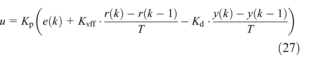
The control block diagram is shown in Figure 6. As mentioned above, Kp reflects the system stiffness, while Kd represents the system damping property. The control parameter can be tuned using a trial-and-error method as follows:
Use a square wave voltage as system input to test the open-loop linearity;
Initialize ΔKp, Kd, and Kvff to 0 and start tuning Kp from a small value. Increase Kp gradually until the system begin to oscillate at a certain amplitude and then set Kp to 0.7 times the oscillate point;
Gradually increase Kd until the system fluctuation occurs and then decrease it and eliminate the fluctuation. To avoid evident disturbance and noise, set Kp to 0.75 times its current value;
Keep Kvff slightly greater than Kd when tuning and change Kp and Kd slightly to obtain a better performance.
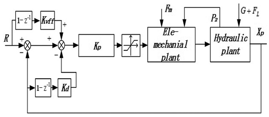
Control block diagram of NPCS.
Simulations
Controller gains are tuned according to the proposed tuning process. Both closed-loop step response and triangle path tracking are tested with certain sets of controller parameters. The simulation parameters are listed in Table 1.
Simulation parameters.

Step response performance for three sets of control gains is shown in Figure 7. The first set employs a relatively smaller constant proportional gain, and the second set uses a relatively high constant proportional gain, and an appropriate proportional gain is applied for the third set. Apparently, the high gain set shows a fast rise time of 40 ms and an overshoot of 8.9%, while the low gain set guarantees a slow rise time of 107 ms but without overshoot, and the appropriate gain set presents a rise time of 67 ms and no overshoot. The changeable gain set shows the most excellent property with a rise time of 37 ms and a slightly overshoot of 1.6%. All four sets of controller parameters ensure the system with a steady-state error of <0.1 µm.

Step response simulation of NPCS.
Control results of triangle path tracking simulation are shown in Figure 8. A maximum tracking error of 2.3 µm is observed for the high gain set and 1.5 µm for the low gain set. The appropriate gain set behaves well with a maximum tracking error of 1.2 µm. As a word, the changeable gain set shows precise and fast response on both step response and triangle path tracking simulations.
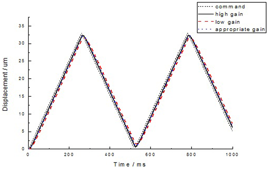
Triangle path tracking simulation of NPCS.
Experiments
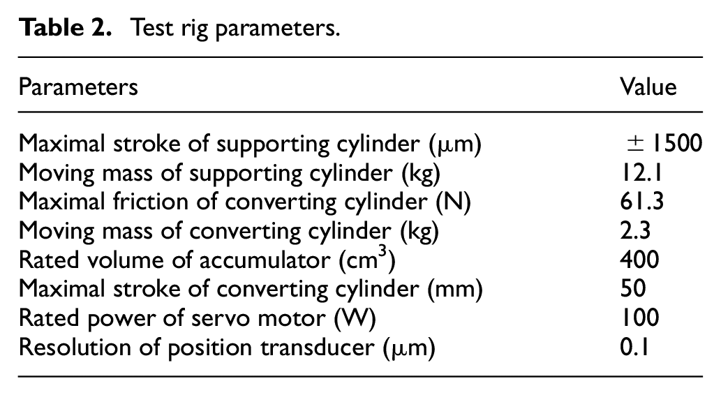
The parameters of the test rig are summarized in Table 2.
Test rig parameters.
All control gains are tuned according to the proposed tuning process, which is similar with the simulation above. All the controller gains are listed in Table 3.
Controller gains.

As shown in Figure 9, the high proportional gain ensures the fastest rise time of 69 ms and a maximum overshoot of 13.05%. Conversely, the low proportional gain assures the system of no overshoot, but the rise time and settling time are lengthened to 230 ms. Intermediately, an appropriate set of control gains guarantees a moderate rise time of 96 ms with a slight overshoot of 2%. Apparently, all the above control gains ensure the system with a steady-state error of <0.5 µm. In a word, the adopted controller presents a precise and fast positioning ability for the proposed actuator partition.

Step response experiments of actuator partition.
Figure 10 shows the results of triangle path tracking experiment. All three sets of parameters are verified with their tracking ability. Yet a time delay ranging from 50 to 100 ms is observed.

Triangle path tracking experiments of actuator partition.
Discussions
Simulation and experiment results verify the usability of the adopted PD controller. Both results indicate that as the proportional gain becomes higher, the control response becomes faster and meanwhile the overshoot becomes larger. Also, compared to the simulation results, the experiment result reveals a time delay of appropriately 22 ms in step response test and a larger time delay in triangle path tracking experiments. In order to promote the system performance with faster response and less overshoot, a PD controller with changeable proportional gain is utilized in the following.
PD controller with changeable proportional gain
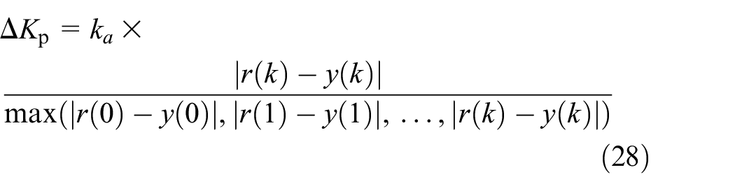
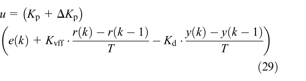
In industry applications, classical PID controllers are always set up with constant control parameters, and such controllers do not perform well enough. The controller can be optimized by increasing the proportional gain when the tracking error is large to fasten response and decreasing the proportional gain when the tracking error is small to avoid large overshoot. An ameliorating proportional gain ΔKp defined by equation (28) is added to equation (27) to obtain an improved property by fastening response without introducing undesirable influence. The modified control law is depicted in equation (29)
The modified PD controller behaves as predicted, as shown in Figure 11. NPCS shows faster dynamic behavior with a rise time of 78 ms and almost no overshoot. A time delay of 22 ms still exists.

Step response of PD controller with changeable gain.
Position keeping experiment of PMSS
A precise and fast position control system is designed so far. The application of NPCS on PMSS is discussed in this section. The overall platform rig is partly shown in Figure 12. All the three actuator partitions share an accumulator, and each actuator partition contains three supporting cylinders.

Test rig of PMSS.
The aforementioned simulations and experiments assume that each NPCS contains only one supporting cylinder. However, each actuator partition may include three or more supporting cylinders in reality, and the three supporting cylinders in the partition do not share the same output displacement and then a position sensor is installed in the virtual pivot supporting point to monitor the output displacement of the actuator partition.
Relocation of virtual pivot supporting point
Coupling effect description and experiments
If the general movements of the primary mirror can be subdivided elementary tasks actuated by one actuator, we can call it a decoupled manipulator. The actuators of the coupled systems influence others’ behavior, and consequently, the decoupled system always shows faster tracking ability and more stable behavior.27,28
Figure 13 shows the difference between coupled and decoupled PMSS control diagrams. The primary mirror position and attitude are determined by a set of position bias between primary mirror and mirror cell [

PMSS control diagram: (a) coupled system and (b) decoupled system.
In the following experiment, the position sensors monitor the position of all three virtual pivot points, and the measured values are recorded. A movement of 20 µm is made in partition 1, if the position sensors 2 and 3 are installed correctly on the virtual supporting.
A strong coupling effect can be seen from Figure 14. In Figure 14(a), a maximum absolute displacement of 3.4 µm is found for partition 2 and 2.6 µm for partition 3. In Figure 14(b), the maximum absolute displacement is 1.2 µm for partition 1 and 2.9 µm for partition 3. In Figure 14(c), the maximum absolute displacement is 3.0 µm for partition 1 and 4.9 µm for partition 2. In a word, the coupling ratio ranges from 6% to 24.5%, which means that none of the sensors completely reflects the output placement of the corresponding partition.
Coupling effect among actuator partitions before decoupling: (a) coupling effect of partition 1, (b) coupling effect of partition 2, and (c) coupling effect of partition 3.
Decoupling measurement and experiments
To weaken the coupling effect, an operative method is presented to relocate the precise position of the virtual pivot points using a differential evolution algorithm.
The overall procedure is described as follows:
Choose predesigned virtual pivot point locations as the current locations;
Change the virtual pivot point locations with small steps around the current locations using a differential evolution algorithm as shown in Figure 15.
Calculate the output displacement of three partitions with the revised virtual pivot point location based on the historical data. If the coupling effect is small enough in the inactive partitions, replace virtual pivot point locations with the new one and go to step 4. Otherwise, go back to step 2;
Use the new displacement of the relocated virtual pivot point as partition displacement feedback and verify the coupling effects on the test rig.

Working procedures of a differential evolution algorithm.
The same experiments are carried to evaluate the measurement, and relevant results are shown in Figure 16. Compared with Figure 14, the coupling effect causes a maximum unwanted displacement ranging from 0.5 to 1.1 µm with a maximum corresponding effect ratio ranging from 2.5% to 5.5%, which is 6%–24.5% before the decoupling measurements. Overall, the proposed method removes most of the coupling effect. After relocation of virtual pivot supporting points, the calculated output displacements of each actuator partition are selected as the feedback displacements of position control systems instead of position sensor measured values, which make the whole PMSS a less coupled system, namely, a decoupled system.

Coupling effect among actuator partitions after decoupling: (a) coupling effect of partition 1, (b) coupling effect of partition 2, and (c) coupling effect of partition 3.
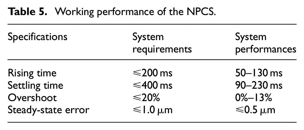
Position and attitude keeping experiments
The major purpose of PMSS is to compensate the position bias when the environment changes. For the following experiments, the whole PMSS is installed on a large swivel table. The mirror cell was controlled to rotate around the X-axis with an angular speed of nearly 10°/s, and the position bias is recorded under three different occasions: PMSS out of control, coupled PMSS under control, and decoupled PMSS under control.
PMSS out of control
Under this occasion, no action is taken to compensate the position bias. As a result, a maximum position bias of 9.1 µm is observed at the maximum inclination (Table 4). The bias is mainly caused by load distribution, so when the inclination increases, the bias becomes larger.
Position bias out of control.

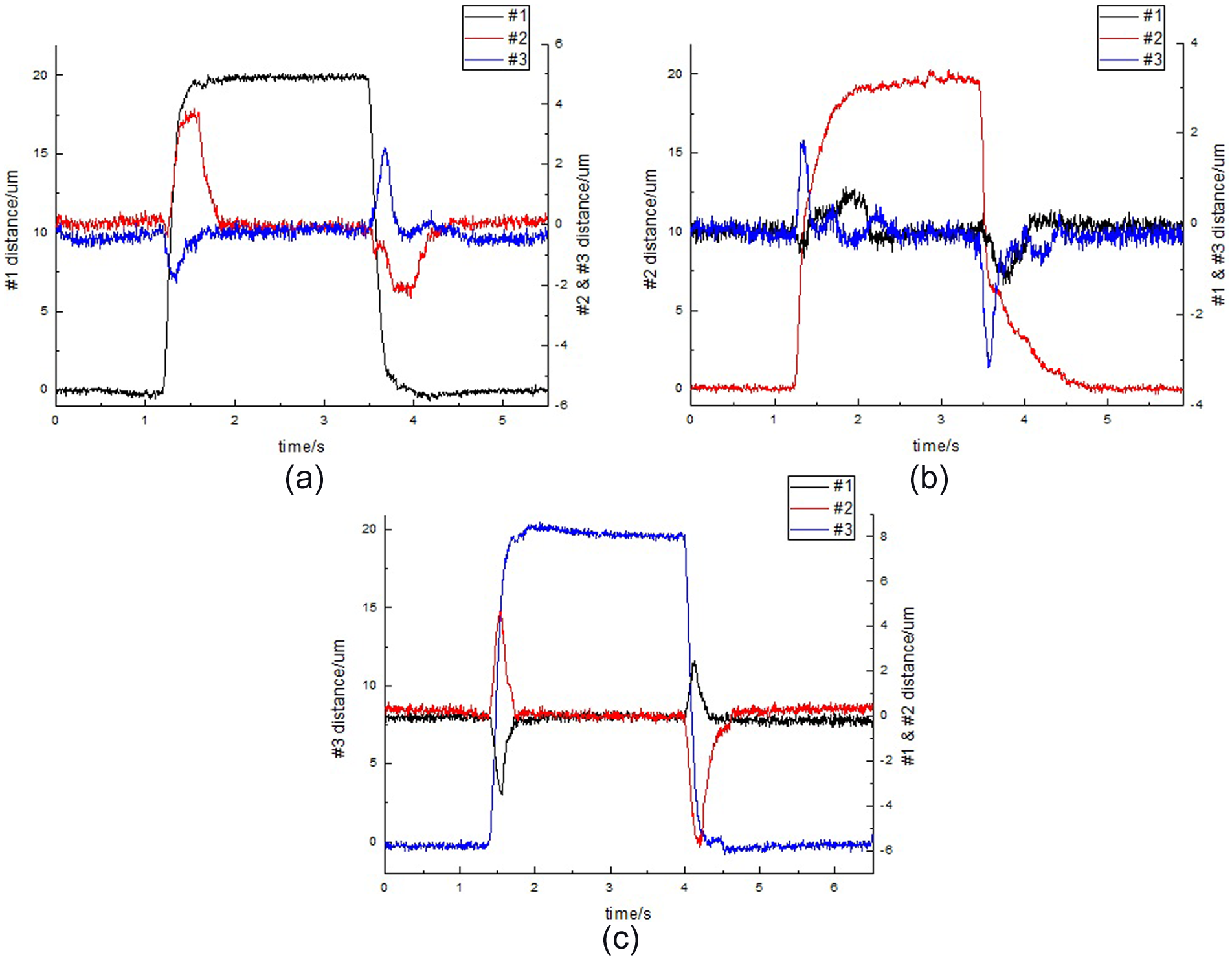
Coupled PMSS under control
Under this occasion, three NPCSs work together to compensate the position bias. The position sensor measured values are selected as the feedback displacements of NPCS.
As shown in Figure 17, the maximum position bias is 1.0 µm for partition 1, while it is −1.0 µm for partition 2 and −2.0 µm for partition 3. When bias occurs in one partition, the other two partitions present bias immediately due to coupling effect, and the recovery procedure lasts for a longer time.

Position bias of the coupled PMSS.
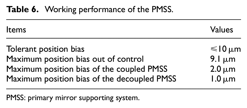
Decoupled PMSS under control
Under this occasion, the calculated output displacements of each actuator partition are selected as the feedback displacements of NPCS, and three NPCSs work together to compensate the position bias.
The position keeping performance is shown in Figure 18. The maximum position bias is 0.3 µm for partition 1, while it is 1.0 µm for partition 2 and 0.4 µm for partition 3. The most apparent position bias is found in partition 3; yet it hardly influences the control action of the other two partitions, and the recovery procedure is quite short compared with that of coupled systems.

Position bias of the decoupled PMSS.
Conclusion
This article has introduced a novel electro-hydraulic position control system and applied it in the supporting system to maintain primary mirror position and attitude. The performance of the proposed system is clarified in Tables 5 and 6, and the conclusion is drawn as follows:
The NPCS ensures the supporting system with theoretically uniform output force on supporting points. As the telescope becomes larger, the mechanical structure of such supporting system remains a one-level structure, which is much simpler than traditional structure with three levels;
With the help of classical PD controller, the NPCS using a servo motor and a converting cylinder shows fast micrometer-level positioning ability with a settling time of <200 ms and almost no overshoot. A modified PD controller ensures the novel system with faster response;
By regulating the output displacement of the NPCS, the primary mirror presents excellent position keeping ability with a maximum position bias of 2 µm when the mirror cell rotates at a considerably high rate;
After relocation of virtual pivot supporting point, the coupling effects of different actuator partitions are mostly removed, and the supporting system shows superior property with a maximum position bias of <1 µm.
Working performance of the NPCS.
Working performance of the PMSS.
PMSS: primary mirror supporting system.
Footnotes
Appendix 1
Academic Editor: Hamid Reza Shaker
Declaration of conflicting interests
The author(s) declared no potential conflicts of interest with respect to the research, authorship, and/or publication of this article.
Funding
The author(s) disclosed receipt of the following financial support for the research, authorship, and/or publication of this article: National Basic Research of China (“973” program; grant nos 2013CB035400 and 2015CB058103), National High Technology Research and Development Program of China (“863” program; grant no. 2012AA041803), and the Science Fund for Creative Research Groups National Natural Science Foundation of China (grant no. 51221004).