
Abstract
In the dynamic study of the double-helical gear transmission, the coupling shaft in the middle of the two helical gears is difficult to be handled accurately. In this article, the coupling shaft is treated as the Timoshenko beam elements and is synthesized with the lumped-mass method of the two helical gear pairs. Then, the numerical integration method is used to solve the amplitude–frequency responses and dynamic factors under diverse operating conditions. A gear vibration test rig of closed power circuit is developed for in-depth experimental measurements and model validation. After comparing the theoretical data with the practical results, the following conclusions are drawn: (1) the dynamic model with the Timoshenko beam element is quite appropriate and reliable in the dynamic analysis of double-helical gear transmission and is of great theoretical value in the accurate dynamic research of the double-helical gear transmission. (2) In both theoretical analysis and experimental measurements, the dynamic factors of gear pair diminish with the increase in the input torque and augment with the increase in the input speed. (3) The deviation ratio of the theoretical data and the experimental results decrease with the increase in the input torque, reaching the minimum at the highest input speed.
Keywords
Introduction
Compared with the single-helical gear, the double-helical gear, also known as the herringbone gear, has the advantages of high carrying capacity, smooth transmission, and small bearing load. 1 In recent years, the double-helical gear transmission system is widely used in aviation and vessel transmission device, and much attention is given to the dynamic characteristics of double-helical gear sets. M Ajmi and P Velex 2 presented a model to analyze the quasi-static and dynamic behavior of double-helical gears, and the model accounted for the time-varying nonlinear meshing stiffnesses, gear and pinion distortions, shape modifications, and floating parts. ZB Zhu et al. 3 studied a dynamic model of the double-helical planetary gear sets using the pairs of gear coupling. YH Liao et al. 4 established a bearing–gear coupling nonlinear dynamic model in a two-stage split double-helical gear transmission, which treated the double-helical gear as two cylinder helical gears, and the impact of the coupling shaft was ignored. F Wang et al. 5 created a bend–torsion–shaft coupling nonlinear vibration model with 12 degrees of freedoms and introduced the time-varying meshing stiffness, the meshinging impact, and the backlash. JS Guo et al. 6 carried out a study to investigate a bend–torsion–shaft coupling nonlinear vibration model with the time-varying meshing stiffness and the meshing impact. C Wang et al. 7 developed a three-dimensional dynamic model of the double-helical gear transmission with the concentrated parameter theory. ZH Sheng et al. 8 established the dynamic model of the double-helical planetary gear system with three-dimensional motion. In most of these aforementioned studies, the double-helical gear is treated as two helical gears with the equal helix angle but the opposite directions, and the effect of the coupling shaft of the double-helical gear is treated as the effect of stiffness and damping. The literature review presented above reveals that the stiffness and damping model is widely used for the coupling shaft of the double-helical gear. In this model, the bending, the tension–compression, and the torsional stiffness and damping are all calculated with the theory of mechanics of materials and are substituted into the equilibrium equations of the system so as to further analyze the dynamic characteristic of the system. The reason why this method is so prevalent is its good legibility and computability. Nevertheless, the model is too simple and the effect of the coupling shaft is not considered sufficiently, which would significantly affect the accuracy and reliability of the dynamic model.
In recent years, a new dynamic model of the double-helical gear had been presented, and the improved model introduces the finite element theory into the classical lumped-mass dynamic model of the double-helical gear.9,10 P Sondkar 9 created a dynamic model of the double-helical planetary gear sets, which introduced the effects of the transmission error, the gyroscopic effect, and the time-varying meshing stiffness. The coupling shaft between the two helical gears is deemed as Euler–Bernoulli beam elements, coupling the bilateral nodes created with the lumped-mass method. In this model, the finite element theory and the classical lumped-mass method are applied together. By assembling the mass and stiffness matrices of the gears and the Euler–Bernoulli beam elements, the coupling effect of two helical gears and the coupling shaft is taken into account.
The Euler–Bernoulli beam element and the Timoshenko beam element are widely used in the finite element analysis.11,12 The Euler–Bernoulli beam element is focused on bending deflection, but the shear deformation and the rotation of cross section are ignored. This Euler–Bernoulli beam element is mainly applied to the slender solid beams. The Timoshenko beam is developed on the basis of the theory of Euler–Bernoulli beam, which considers the dynamic effect of the shear deformation and the rotation of the cross section and is especially suitable for the height-span and hollow beam. The coupling shaft of the double-helical gear is a short hollow shaft generally, and the shear deformation caused by the transverse shear stress would induce additional deflection in the shaft and then the cross section is no longer perpendicular to the axis as before. Above all, the shear deformation and the rotation of cross section cannot be ignored, and the Timoshenko beam element is more reasonable and efficient than the Euler–Bernoulli beam element in the dynamic analysis of the double-helical gear.
In this article, the coupling shaft of the two helical gears is treated as Timoshenko beam elements, and the two helical gear pairs are simplified using the lumped-mass method. The synthesized model includes the time-varying meshing stiffness, the time-varying support stiffness of the sliding bearing, and the integrated transmission error in the dynamic analysis simultaneously. The corresponding dynamic equations are solved using the numerical integration method and then the amplitude–frequency responses and the dynamic factors are obtained in various operating conditions. Finally, a gear vibration test rig of closed power circuit is established and the experimental amplitude–frequency responses and dynamic factors are also acquired under the aforementioned operating conditions. By comparing the experimental results with the theoretical data, the accuracy and reliability of the dynamic model with the Timoshenko beam element are verified.
Dynamic model formulation
Equations of motion
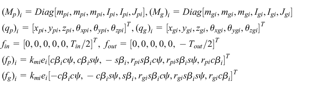
As shown in Figure 1, the dynamic model of the double-helical gear transmission system is established with the lumped-mass method.13–15 The transmission system consists of an external double-helical gear pair and four sliding bearings. The double-helical gear is deemed to be two helical gears whose helix angles are in opposite directions. The input torque acts on the two driving helical gears, and the output torque acts on the two driven helical gears. The coupling shafts of the double-helical gears are treated as two tandem Timoshenko beam elements. {kζx, cζx, kζy, cζy, kζz, cζz} (ζ = p, g) are the support stiffness and damping of the sliding bearings, which act on the middle node of the two coterminous Timoshenko beam elements. mpi and mgi are the masses of the helical gear; Ipi, Igi, Jpi, and Jgi are the diametral and polar mass moments of inertia of the helical gear, all of which are concentrated on the geometric centroids, respectively. Every node has 6 degrees of freedom {x, y, z,θx,θy,θz}. The meaning of the other parameters in Figure 1 is as follows: Tin and Tout are the input and output torques, respectively; nin and nout are the input and output rotation speeds, respectively; kmi and cmi are the meshing stiffness and damping, respectively; ei is the integrated transmission error; βi is the helix angle; and ψ is the pressure angle. The meaning of the subscripts is as follows: p and g denote the driving and driven of the gear pair, respectively; i = L, R denotes the left or right helical gear of the double-helical gear; and x, y, and z are the three directions of the coordinate. In addition, cψ ≡ cos(ψ), sψ ≡ sin(ψ), cβi ≡ cos(βi), and sβi ≡ sin(βi) in this article.

Dynamic model of double-helical gear transmission.
According to Newton’s second law, the dynamic equations of unilateral helical gear pair i (i = L, R) of the double-helical gear transmission are shown as follows

The symbol “

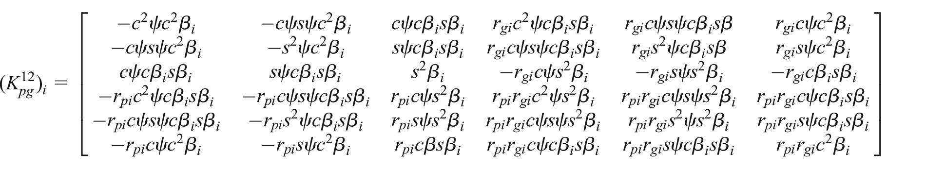
After substituting equation (1) into equation (2) and transforming the equations into matrix form simultaneously, the equations can be expressed by

where


As mentioned above, the Timoshenko beam elements are used to couple the helical gears on the left and right sides of the double-helical gear. The schematic diagram of the double-helical gear with Timoshenko beam elements is shown in Figure 2. 9
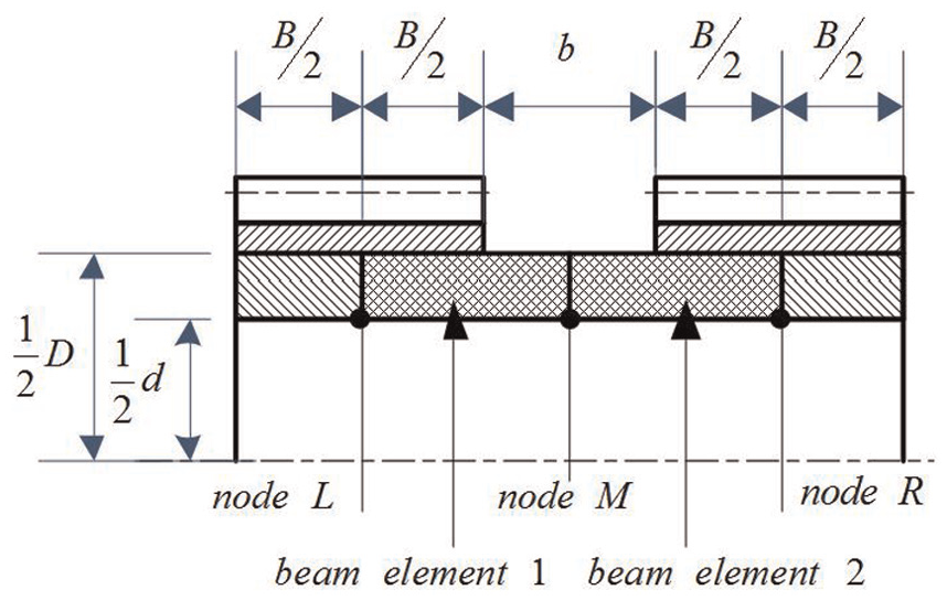
Schematic of double-helical gear with Timoshenko beam elements.
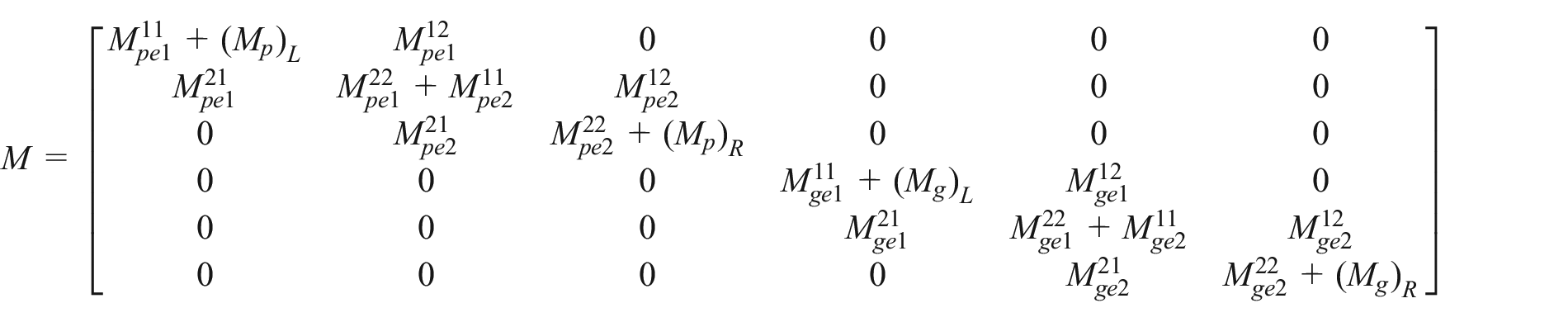
In Figure 2, d is the inner diameter of the double-helical gear shaft, and B is the face width of the single helical gear. D is the outside diameter of the coupling shaft, and b is the length of the coupling shaft. The coupling shaft treated as Timoshenko beam elements 1 and 2 spans from the midpoint of the right tooth surface to the left. The masses and the rotational inertias of the left helical gear concentrate on node L. It is applicable for node R as well. The mass and the rotational inertia of the coupling shaft concentrate on the nodes of every Timoshenko beam element, respectively. The node M is used to connect the bilateral helical gears and the coupling shaft with the stiffness and damping matrices that represent the support effect of the sliding bearings. The stiffness and mass matrices are given as follows

where qζ = [(qζ) L , (qζ) M , (qζ) R ] T (ζ = p, g) is the corresponding displacement vector; and (qζ) L , (qζ) R are equivalent with (qp) i , (qg) i in equation (3).
Timoshenko beam element
The schematic of a three-dimensional Timoshenko beam element of two-node and 6 degrees of freedom is shown in Figure 3. qe = [x1, y1, z1, θx1, θy1, θz1, x2, y2, z2, θx2, θy2, θz2] T is the generalized displacement vector of the element. l is the length of the element, and A is the cross-sectional area of the element.

Schematic of Timoshenko beam element.
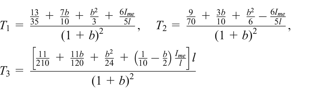
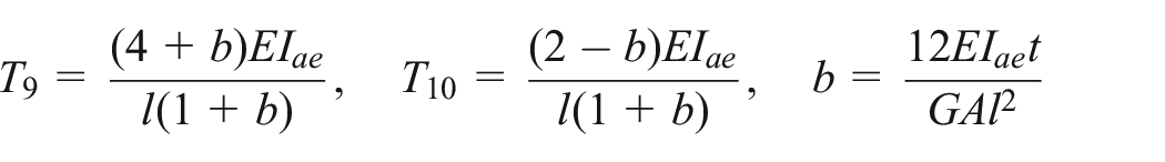
The Timoshenko beam element is developed on the basis of the classical beam (Euler–Bernoulli beam) theory by taking the shear deformation into account. Given that the structure of coupling shaft is simple, and could be regarded as an issue of linear elasticity, the superposition principle is applicable here. The procedure to handle the influence of the shear deflection is as follows: the beam deflection is divided into two parts which are caused by bending and shear, respectively, and the two kinds of deflections are subsequently analyzed with the classical beam theory separately, and thereafter, the desired consequence could be obtained through the superposition of the two results. The stiffness and mass matrices of the nth (n = 1, 2) Timoshenko beam element and the deducing process could be found in Wang 16 , Doyle 17 , Pilkey, 18 and Du et al. 19 me is the mass of the element per unit length. Ime and Jme are the diametral and polar mass moments of inertia of the element per unit length, respectively. Iae and Jae are the diametral and polar area moments of inertia of the element, respectively. E and G are Young’s modulus and the shear modulus of elasticity, respectively. t = 0.75 is defined as the correction factor for circular cross section. The matrices and the other symbols are shown as follows


Equation (4) is assembled systematically with equation (3) and then the overall dynamic equations of the double-helical gear are obtained

where M is the mass matrix, and K = Kmesh + Kb is the overall stiffness matrix which consists of the meshing stiffness matrix Kmesh and the support stiffness matrix Kb. q(t) is the overall displacement vector. F(t) is the overall force vector. The parameters can be shown in matrix form as follows

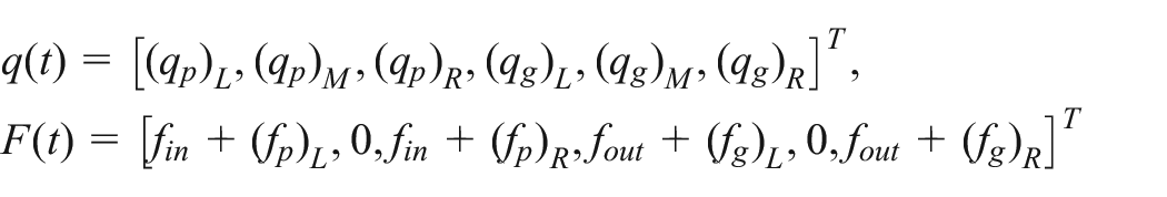
The support stiffness matrix Kb is defined as Kb = diag [0 Kbp 0 0 Kbg 0]. Kbp and Kbg are the support stiffness matrices of 6 degrees of freedom of the sliding bearings given as Kbζ = diag [Kζx Kζy Kζz 0] (ζ = p, g), acting on node M in Figure 2. C is the proportional damping matrix given as C = ς1K + ς2M, and ς1 and ς2 are the proportionality constants.
Equation (5) is a positive semi-definite differential equation with 24 degrees of freedom, for θ is the displacement in the torsion direction and is not subject to the constraints. The rigid body displacement of the gear transmission system can be removed by the soft-spring-fixing method, 20 which introduces a spring into the output of the double-helical gear transmission system to constrain the torsion displacement. The order of magnitude of the spring stiffness is not more than 102 generally, much smaller than the support stiffness, the meshing stiffness, and the torsion stiffness of the system, and the additional spring has little influence on the dynamic response accordingly. Thereupon, a stiffness of kfix = 4 × 10² N m/rad is added to the 24th row and the 24th column in the K matrix in equation (5).
After dimensional normalization, the equation of motion can be expressed as

where M, C, K, F, and Q are the mass matrix, the damping matrix, the stiffness matrix, the torque vector, and the displacement vector, respectively.
Dynamic parameters
The time-varying meshing stiffness of the gear pair can be expressed as 21
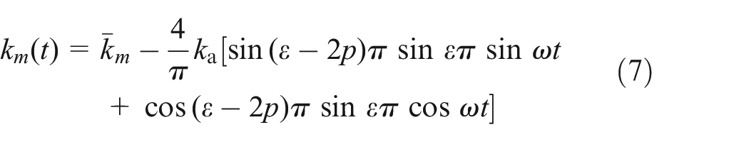
where the amplitude ka and the mean value
The support stiffness and damping of the sliding bearings {kζx, cζx, kζy, cζy, kζz, cζz} (ζ = p, g) are solved with the neural network method and can be acquired in Wang. 22
The integrated transmission error is a comprehensive parameter, and the parameter synthesizes the effect of the manufacturing errors and the installation error and can be defined as23,24

where the amplitude of the transmission error Ae is given according to the accuracy of the gear system. ϕ is the initial meshing phase of the gear pair.
Dynamic analysis
Basic parameters
The basic parameters of the double-helical gear transmission system are shown in Table 1.
Basic parameters.

Solution of equation
In order to solve the dynamic equations, the Runge–Kutta numerical integration is implemented out to acquire the relative meshing displacement δL and δR and the geared speeds
According to Sondkar 9 the dynamic model with the Euler–Bernoulli beam element is more effective and accurate than the conventional dynamic model in the dynamic analysis of the double-helical gear transmission. And section “Introduction” states that the dynamic model with the Timoshenko beam element should be more precise than the dynamic model with the Euler–Bernoulli beam element theoretically in the dynamic modeling of the double-helical gear transmission. For verifying the superiority of the dynamic model with the Timoshenko beam element, the dynamic model with the Euler–Bernoulli beam element is established and the dynamic equations are solved with the Runge–Kutta numerical integration method and then the dynamic factors are computed with the same method mentioned above.
In order to carry out a systematic theoretical analysis of the double-helical gear transmission, 18 operating conditions (six input speeds 1200, 1450, 1700, 1950, 2200, and 2450 r/min and three input torques 130, 210, and 290 N m) are used to carry on the theoretical operation. The theoretical amplitude–frequency responses and the theoretical dynamic factors of two theoretical models under three operating conditions are listed in Figures 4 and 5.
Theoretical amplitude–frequency responses and dynamic factors of dynamic model with Euler–Bernoulli beam element: (a) spectrogram of vibration acceleration 130 N m–1200 r/min, (b) dynamic factor (1.1903) 130 N m–1200 r/min, (c) spectrogram of vibration acceleration 210 N m–1950 r/min, (d) dynamic factor (1.1309) 210 N m–1950 r/min, (e) spectrogram of vibration acceleration 290 N m–2450 r/min, and (f) dynamic factor (1.1057) 290 N m–2450 r/min.

Theoretical amplitude–frequency responses and dynamic factors of dynamic model with Timoshenko beam element: (a) spectrogram of vibration acceleration 130 N m–1200 r/min, (b) dynamic factor (1.2359) 130 N m–1200 r/min, (c) spectrogram of vibration acceleration 210 N m–1950 r/min, (d) dynamic factor (1.1655) 210 N m–1950 r/min, (e) spectrogram of vibration acceleration 290 N m–2450 r/min, and (f) dynamic factor (1.1620) 290 N m–2450 r/min.
Dynamic experiment
Experimental rig
In this article, a vibration test rig of closed power circuit of the double-helical gear transmission is established with the parameters in Table 1. Since this kind of test rig only consumes a small amount of energy to meet the operating conditions, cooling devices could be ignored to simplify the entire experiment facilities. The schematic diagram of the test rig is shown in Figure 6. The test rig is composed of an accompanying gear box and a test gear box. Both of them are of double-helical gear transmission with the same parameters, except that the support devices are different. The gears in the accompanying gear box are supported by the rolling bearings; however, the driving gear in the test gear box is supported by the tilting pad journal bearings, and the driven gear is supported by the cylindrical sliding bearings. The use of the tilting pad journal bearings and the cylindrical sliding bearings together can compensate the axial load and reduce the axial vibration, and the operation state of the test rig will be close to the theoretical analysis of the dynamic model to the largest extent. Two elastic shafts are used to connect the two gear boxes. The elastic shafts can stockpile the deformation energy and form the closed power circuit of the test rig. In the experiment process, the direct current (DC) electric motor only needs to overcome the frictional resistance of the test rig.

Schematic of gear vibration test rig of closed power circuit.
The test rig is shown in Figure 7 and is driven by a DC electric motor whose speed is regulated by a programmable logic controller (PLC). The DC electric motor connects to the left end of the pinion shaft of the accompanying gear box through a couple of pin couplings with elastic sleeves, and the right end of the pinion shaft connects to the torque meter and then connects to the high-speed elastic shaft through couplings. The torque meter can measure the torque of the high-speed elastic shaft in real time, which is the input torque of the test gear box. The right end of the high-speed elastic shaft connects to a couple of loaded flanges with a couple of couplings. The loaded flanges can be exerted on a quantitative torque via the loaded wrench. The right loaded flange connects to the left end of the pinion shaft of the test gear box. The driven shaft of the test gear box connects to the driven shaft of the accompanying gear box through the low-speed elastic shaft with a couple of couplings. Two high-speed circular grating encoders are installed on the extension of the driving and driven shafts of the test gear box, respectively, with two pairs of diaphragm couplings. The circular grating encoder is an angular sensor and used to measure the angular displacement between the driving and driven shafts in the experiments, and the signals are sampled with PCI8514 data acquisition card. The signals are analyzed with data analysis software programmed by C# and MATLAB and then the relative meshing displacements, the relative speeds, and the relative accelerated speeds in the direction of action line can be acquired. The data acquisition interface of the PCI8514 and the data computation interface of the software are shown in Figure 8.

Gears vibration test rig of closed power circuit.

UI of data processing: (a) data acquisition interface and (b) data computation interface.
Experimental procedure
With the purpose of contrasting the theoretical analysis results, 18 identical operating conditions (six input speeds 1200, 1450, 1700, 1950, 2200, and 2450 r/min and three input torques 130, 210, and 290 N m) are employed in the experiment. The experimental procedure is as follows:
Examine the test rig, turn on the computer and the sensors, launch the lubricating oil system of the sliding bearings, and run for 5 min under a steady state.
Start the data acquisition system, acquire three groups of data (the interval time is 10 s), compare the difference of the data, and confirm that the data acquisition system is under a normal state, otherwise adjust it.
Apply the torque with the loaded wrench according to the minimum load presented above and record the value of the torque meter.
Start the DC electric motor, regulate the PLC to the minimum input speed presented above, open the data acquisition software after running for 2 min, and record the experiment data of the current operating condition.
Increase the input speed, return to Step 4, and have a test at another input speed, till all the input speeds are tested.
Stop and refrigerate the test rig for 10 min, return to Step 3, increase the input torque, and have another test at another input torque, till all the input torques are tested.
Turn off the test rig and analyze the experimental results.
Experimental results and discussion
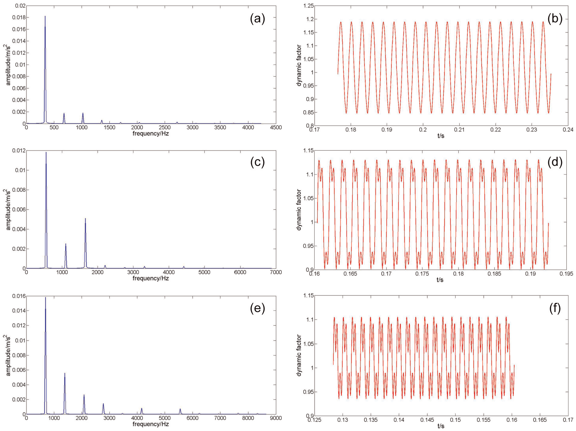
The experimental amplitude–frequency responses and the experimental dynamic factors can be obtained with the method of section “Solution of equation.” In addition, in order to facilitate the results comparing and analysis, the filtering technique is used in the data processing to eliminate the negative influences of the white noise. The experimental amplitude–frequency responses and the experimental dynamic factors of three different operating conditions corresponding to Figures 4 and 5 are shown in Figure 9.

Experimental amplitude–frequency responses and dynamic factors: (a) spectrogram of vibration acceleration 130 N m–1200 r/min, (b) dynamic factor (1.2720) 130 N m–1200 r/min, (c) spectrogram of vibration acceleration 210 N m–1950 r/min, (d) dynamic factor (1.2081) 210 N m–1950 r/min, (e) spectrogram of vibration acceleration 290 N m–2450 r/min, and (f) dynamic factor (1.1667) 290 N m–2450 r/min.
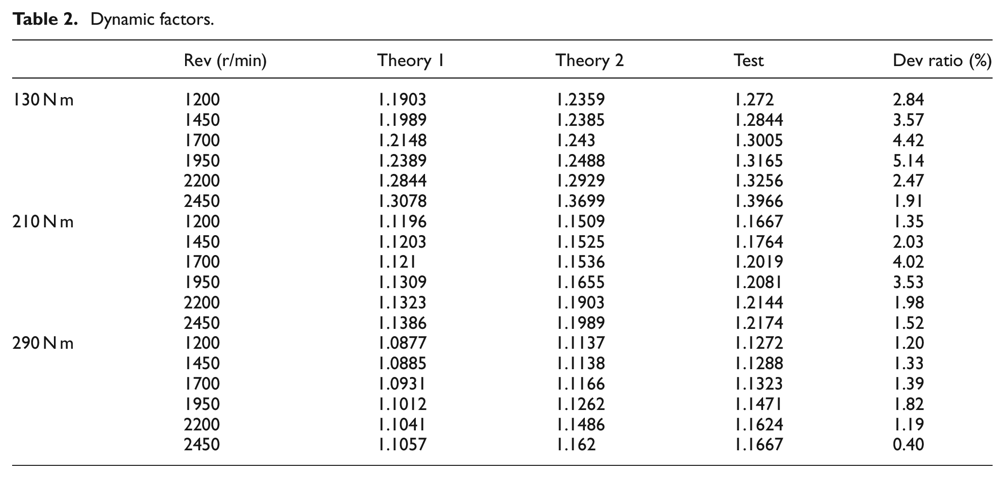
The theoretical results and experimental data of the dynamic factors are summarized in Table 2 and Figure 10. In Table 2, Rev is the input speed of the driving gear, Theory 1 is the theoretic results of the dynamic model with Euler–Bernoulli beam element, Theory 2 is the theoretic results of the dynamic model with Timoshenko beam element, Test is the experimental results of the vibration test rig of closed power circuit of double-helical gear transmission, and Dev ratio is [(dataTest − dataTheory 2)/dataTest] × 100%.
Dynamic factors.

Summary of dynamic factors.
Figures 4, 5, 9, and 10 and Table 2 show that
The theoretical and experimental amplitude–frequency responses indicate that the theoretical harmonic frequencies of both dynamic models show a satisfactory agreement with the experimental harmonic frequencies. At several primary low-order harmonic frequencies, the theoretical harmonic amplitude proportions of the dynamic model with Timoshenko beam element are more consistent with the experimental harmonic amplitudes than the dynamic model with Euler–Bernoulli beam element. The dynamic factors of the dynamic model with Timoshenko beam element are much closer to the experimental results than the dynamic model with Euler–Bernoulli beam element. Under 18 different operating conditions, the deviation ratios of the theoretical data based on Timoshenko beam element and the experimental results are very low, and the maximum is 5.14% at 130 N m, 1950 r/min and the minimum is 0.4% at 290 N m, 2450 r/min, and most of the rest are below 3%. So the dynamic model with Timoshenko beam element can elaborate the structure and the dynamic characteristic more accurately and reliably than the dynamic model with Euler–Bernoulli beam element and has a great theory value in the dynamic analysis of the double-helical gear transmission.
The theoretical data of the dynamic model with Timoshenko beam element indicate that the dynamic factors augment with the increase in the input speed in the case of identical input torque. Figure 10 shows that the theoretical dynamic factors based on Timoshenko beam element increase remarkably at 130 N m, especially after the input speed exceeds 2200 r/min and rises gradually at 210 and 290 N m. The experimental results of the vibration test rig verify these conclusions. Moreover, the deviation ratio of the theoretical data based on Timoshenko beam element and the experimental results increases initially and then drops reaching the maximum at 1700 and 1950 r/min and the minimum at 2450 r/min. The reason is that the theoretical analysis is based on an ideal lubrication state of the sliding bearings. In fact, the lubrication film of the sliding bearings needs a high revolving speed, and the lubrication state would become worse with the increase in the input speed before the formation of the lubrication film. Therefore, higher input speed could develop an ideal lubrication state of the sliding bearings, and the theoretical analysis is much closer to the actual running state.
The theoretical data of the dynamic model with Timoshenko beam element indicate that the dynamic factors diminish with the increase in the input torque in a specific input speed, which is consistent with the experimental results. Moreover, the deviation ratio of the theoretical data based on Timoshenko beam element and the experimental results decrease with the increase in the input torque, and the deviation ratio at 290 N m is lower than that at 130 and 210 N m under corresponding input speeds. The reason is that the time-varying meshing stiffness model is deduced based on an ideal engagement state; however, the actual state is not perfect because of the existence of the manufacturing errors such as the tooth surface roughness, pitch deviation, tooth profile deviation, and installation errors. The meshing force between the driving gear and driven gear augments with the increase in the input torque. The meshing stiffness enlarges with the increase in the total length of the action lines, and the engagement of the gear pair tends to an ideal state and the deviation ratio could become lower increasingly. As a result, bigger input torque could develop an ideal engagement state, and the theoretical analysis could be closer to the actual running state.
Conclusion
In this article, a dynamic model of the double-helical gear transmission is established with the lumped-mass method and the Timoshenko beam of the finite element theory. Since the Timoshenko beam includes the mechanical effect of the shear deformation and the rotation of the cross section in theory, it is more suitable for the coupling shaft of the double-helical gear rather than the Euler–Bernoulli beam and the equivalent stiffness and damping. The corresponding dynamic equations are solved with the Runge–Kutta numerical integration and then a vibration test rig of closed power circuit of double-helical gear transmission is set up to verify the theoretical validity of the model with the Timoshenko beam:
The contrast of the theoretical results and the experimental data indicates that the dynamic model with the Timoshenko beam element can describe the dynamic characteristics of the double-helical gear transmission more accurately than the dynamic model with the Euler–Bernoulli beam element. The dynamic model with the Timoshenko beam element is feasible and reliable and has a great theoretical value in the dynamic research of the double-helical gear transmission.
The theoretical analysis of the dynamic model with the Timoshenko beam element indicates that the dynamic factors will augment with the increase in the input speed at a certain input torque and diminish with the increase in the input torque at a certain input speed. The experimental results of the vibration test rig of closed power circuit verify the above-mentioned conclusion in several different operation conditions. Furthermore, this conclusion is in accordance with the earlier studies by RF Li and JJ Wang 14 and JS Guo. 21
The deviation ratio of the theoretical data of the dynamic model with the Timoshenko beam element decreases with the increase in the input torque at a certain input speed and acquires the minimum at the highest input speed at a certain input torque. The experimental results of the vibration test rig of closed power circuit also confirm the conclusion in several different operation conditions. That is to say, the dynamic feature of the double-helical gear transmission device at the higher input speed and bigger input torque is much closer to the theoretical analysis using the dynamic model with the lumped-mass method and the Timoshenko beam of the finite element theory.
In summary, the dynamic model with the Timoshenko beam element and the analytical results presented above are of great significance and show strong potential in the accurate dynamic analysis of the double-helical gear transmission.
Footnotes
Academic Editor: Ramiro Martins
Declaration of conflicting interests
The author(s) declared no potential conflicts of interest with respect to the research, authorship, and/or publication of this article.
Funding
The author(s) disclosed receipt of the following financial support for the research, authorship, and/or publication of this article: The authors gratefully acknowledge the financial support of the National High Technology Research and Development Program of China (2009AA04Z404).