
Abstract
In developing a shoulder prosthesis, in addition to appropriate payload and range of motion under the constraints of weight and shape, impact absorption is very important for safe use. Hybridization of two different actuators (pneumatic elastic actuators with the features of lightness and intrinsic visco-elasticity, and servo motors that have stable torque and a large range of motion in combination with an antagonistic mechanism) was employed to achieve the development of the shoulder prosthesis. A two-link, two-degree-of-freedom arm was used to test the different hybridization configurations in order to investigate the impact absorption. A dynamic simulation platform based on four bimanual activities of daily living was established to obtain the required range of motion and torque for joints of a two-link, four-degree-of-freedom arm. The number of pneumatic elastic actuators required and the dimension of the antagonistic mechanism mechanical structures were optimized using the dynamic simulation platform. The best configuration of the two types of actuators was determined using the dynamic simulation based on the impact absorption results and other criteria. Moreover, a simplified prototype driven by hybrid actuation was made. It was shown that the pneumatic elastic actuator joint could improve impact absorption, and the actuator configuration of shoulder prostheses is activity of daily living dependent. The prototype could reproduce a certain activity of daily living motion, indicating its feasibility in daily living.
Keywords
Introduction
Although prosthetic fingers,1–3 hands,4–8 trans-radials,9–11 and other types of prostheses12,13 have been well studied, there have been few studies on shoulder prostheses. Because shoulder amputees are not able to manipulate their prosthetic arm with a much shorter residual limb, an appropriate output force and range of motion (ROM) are much more necessary than with other prostheses such as hand and trans-radial prosthesis.
In developing a shoulder prosthesis, in addition to appropriate payload and ROM under the constraints of weight and shape, impact absorption is very important for safe use in daily living. However, to the best of our knowledge, there has been no research taking into account these factors, especially safety with validation by testing impact absorption in a comprehensive manner.
Softness of an intact arm could contribute to impact absorption, thus reducing the damage caused by a possible collision with other objects in the course of daily living. Although a motor-actuated mechanism could provide “pseudo-softness” through impedance control with sensory information14,15 it faces a problem with time delays. On the other hand, flexible components are directly introduced to actuator mechanisms for intrinsic softness. These components were springs, a magnetorheological (MR) damper, shape memory alloys (SMAs), a mechanical prismatic slider, and pneumatic elastic actuators (PEAs).6,16–24 PEAs are also called pneumatic muscle actuator.20,22,23 Because the peak value of impact force and acceleration occurs in a very short period of time,25,26 the intrinsic softness has a beneficial effect over “pseudo-softness” on absorbing the impact from an unpredicted collision. In our previous study, a shoulder prosthesis was designed according to a policy that favored PEAs using a 4-degree-of-freedom (DOF) arm model based on a simplistic straight-line trajectory for a motion of typical activities of daily living (ADLs). 27 The impact absorption feature was investigated based on the maximum impact value of a drop impact test with a simplified 1-DOF arm. Apparently, the tests with the 1-DOF arm could not reveal the impact absorption effect of a different combination of actuators.
On the other hand, motors, as actuators, could potentially generate both a large working space and a stable output force. Also, the motion could be controlled to be speedy and accurate. Moreover, motors have advantages of accessibility and cost-effectiveness. In related work of shoulder prostheses, higher DOFs and multifunctional arms driven by motors have been studied.28–32 The arm 29 for targeted muscle reinnervation (TMR) is considered to be an especially state-of-the-art technology. However, such motor devices generally have less back-drivability, due to the strong holding torques and multiple reduction gear. This means that a prosthetic arm and its joints are rigid and could give rise to injuries, because the arm could not cushion the impact of collisions or contacts and consequently convey the impact force to the interface between the prosthesis and the user’s body. Moreover, a motor usually lacks lightness in comparison to its output force. The arm30,31 taking into account wearability (including usability and comfort) and functionality (from the aspect of payload, velocity, and mobility) incorporates a safety device. The safety device consists of a steel pin and a flat spring, which allows the upper arm to freely rotate in case of an unexpected higher external load acting on the arm in order to prevent the impact force due to accidental impacts from being transmitted to the user’s body. However, with respect to the weight, in turn, many prostheses including the abovementioned shoulder prostheses weigh above 2 kg. However, the lighter weight is desirable for amputees.33,34
In this study, a hybridization of two different actuators (PEAs and servo motors) in combination with an antagonistic mechanism (AM) was employed to deal with the design problem. PEAs have lightness, intrinsic visco-elasticity (i.e. safety 35 ), and good power-weight performance compared to standard industrial pneumatic cylinder actuators or motors.36–38 However, they also have a small ROM and a stroke-dependent output force. Moreover, PEAs are slow and inaccurate due to their hysteresis characteristics. The hybridization can take advantage of and compensate for weakness of both the PEA and the motor. 39 A two-link, 2-DOF arm was used to test the different configurations of hybridization, in a series of drop impact experiments, in terms of impact absorption. A dynamic simulation platform based on the motion data of four bimanual ADLs including a drinking motion which was measured in our previous study40,41 was established and used to obtain the required ROM and torque for each joint of the two-link, 4-DOF arm. Because PEAs are prismatic actuators, which could only generate the force by contraction, an AM with a pulley is required in order to generate a bidirectional rotational motion for a joint. The number of PEAs required and the pulley radius in the AM could be optimized using the dynamic simulation platform. Based on the optimization results, the ADL dependency could be investigated. Finally, a prototype could be built and used for investigating the reproducibility of a certain ADL.
Methods
Drop impact test
In order to compare the impact absorbability between the PEA AM and the servo motor joint in a multiple joint situation, drop impact tests were performed on a two-link, 2-DOF arm, which consists of two links, LU (upper arm link) and LF (forearm link), and two joints, JS (shoulder joint) and JE (elbow joint). JS was linked to a sliding table with a rotational shaft and ball bearings. The sliding table was placed on the measurement plane of the sensor of the force gauge (ZTA-DPU-500N, IMADA Corp., 2000 Hz, 500 N). 42 JS and JE were connected to and actuated through the output rotational shaft of the PEAs (PM-10P, SQUSE Inc., Japan, 0.003 kg, 23.8 cm3 (simulated value), maximum 100 N, average contraction ratio 30% per piece) 43 or the motor (RS405CB, Futaba Corp., 0.067 kg, 35.6 cm3, 4.7 N m (48.0 kg cm, gravity acceleration g = 9.8 m/s2)) 44 as shown in Figure 1(a)–(c).

Test arm of two-link-2-DOF: (a) experimental equipment of impact force measurement. The test arm consists of the link LU (upper arm) and LF (forearm) with joint JS (shoulder) and JE (elbow). (b) AM with four PEAs and a pulley of radius r = 30 mm. Its output rotational shaft is connected to JS or JE. (c) Servomotor whose output rotational shaft is connected to JS or JE. (d) Configuration SM-EM in Table 1. The motor in (c) is connected to JS and JE. (e) SP-EM. The AM with four PEAs (b) and motor is connected to JS and JE, respectively. (f) SM-EP. The motor and AM with four PEAs are connected to JS and JE, respectively. (g) SP-EP. The AM with four PEAs is connected to JS and JE.
Four configurations, shown in Table 1 and Figure 1(d)–(g), were tested. In fact, the PEA joint can generate the torque by composing the AM as shown in Figure 1(b). In our previous experiments, the relationship between the stroke xPEA (mm) and output force FPEA (N) of the PEA for air pressures of 0.2 MPa was derived as follows. 27 In the experiments, 27 three pieces of PEAs, which were connected serially, were used for averaging purposes. Weights from 1 kg (9.8 N) to 10 kg (98 N) were added in increments of 1 kg (9.8 N) to the end of the series of PEAs, and 0.2 MPa air pressure was applied (all PEAs were actuated) after adding each weight. The change in length, xPEA, with respect to the unloaded natural length of each PEA piece was measured under each weight, and the measurements were repeated 10 times. The relationship, which was considered to be linear, was shown in the measurement region (9.8–98 N)

Impact test configurations.

PEA: pneumatic elastic actuator; SM-EP: shoulder-motor-elbow-PEA; SM-EM: shoulder-motor-elbow-motor; SP-EM: shoulder-PEA-elbow-motor; SP-EP: shoulder-PEA-elbow-PEA.
Two PEAs were used in parallel on each side as shown in Figure 1(b) (a total of four PEAs), and their lengths were adjusted while considering equation (1), and the radius, r, of the pulley was set to 30 mm in order to compare the PEAs and AM joint with the motor joint under similar conditions.
Weights of 0.98 and 1.96 N were dropped from a height of 30 mm and collided with a cover which was fixed on the LF for avoiding a collision with the PEAs, as shown in Figure 1(a), (f), and (g). When using the PEAs and AM, air pressures of 0.2 and 0.1 MPa were tested. The following are indexes measured in the test. All measurements in the collision experiments were repeated 10 times for averaging purposes. Here, the undernoted average impact difference value represented roughly the vibrational transmission and was measured every 0.0005 s for 0.4 s (800 points) after the collision as shown in Figure 2.
Waveform for 0.5 s (1000 measured points);
First peak of impact force;
Second peak of impact force;
Time from collision to second peak;
Average of impact difference value (Id) for 0.4 s.

Average impact difference value. The average impact difference value per 0.0005 s in waveform for 0.4 s was measured. Moreover, this value was also averaged by 10 repetitions.
ADL measurement
In order to accomplish the goals of the shoulder prosthesis, which is lightweight, simple, and useful for matching the needs of users, the prosthetic mechanism should be designed with a focus on the motion or functions of intended ADLs. This focus leads to an improvement of lightness and simplicity, that is, maintenance and lasting usage.45,46 Unilateral arm amputees are deemed capable of carrying out roughly 80% of ADLs with their intact arm. 47 Therefore, prostheses with functions that support bimanual coordination motions are considered reasonable except for one-handed ADLs. In this article, four such bimanual ADLs were selected as intended motions for development of the prosthesis as follows. The motions were conducted by one healthy subject, who was 170.5 cm tall and right-handed. The left-hand coordinate was measured by a motion tracking system (OptiTrack, 60 Hz) and is depicted as red plots in Figure 3. The position of each part was laid out as shown in Figure 3.
Drinking: reaching for, grasping, unscrewing the top of (by the right hand), and drinking a bottled water of 0.5 kg in a sitting posture;
Putting on socks of 0.05 kg in a sitting posture;
Tying: wearing a tie of 0.05 kg in a standing posture;
Hanging; hanging up a washed cloth (shorts 0.2 kg) using clothespins in a standing posture.
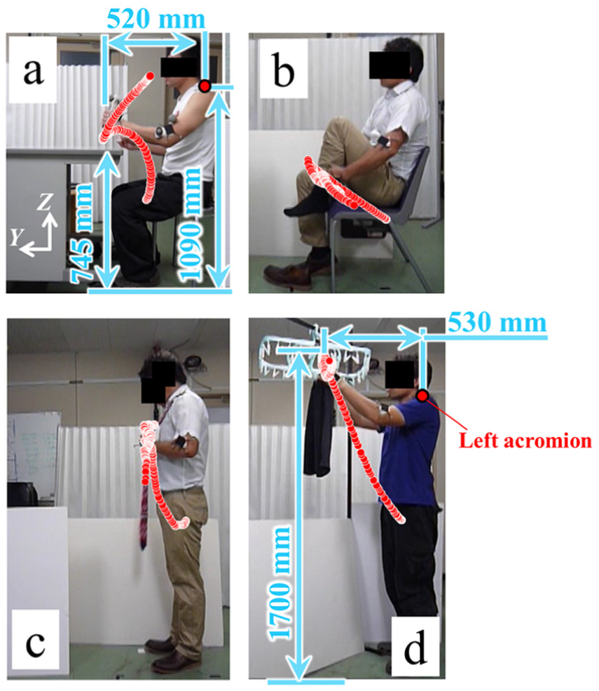
Motions of four ADLs: (a) reaching for, grasping, unscrewing the top of, and drinking bottled water in a sitting posture; (b) putting on socks in a sitting posture; (c) wearing a tie in a standing posture; and (d) hanging up a washed cloth (shorts) using clothespins in a standing posture.
Link model simulation
In order to calculate the required joint ROM and torque when conducting the four ADL motions, a shoulder prosthesis link model for a prototype was developed as shown in Figure 4. The model consisted of two links (upper arm, LUA, and forearm with hand, LFAH), two joints (2-DOF shoulder J1–J2 and 2-DOF elbow J3–J4), and a 1-DOF hand whose ROM and torque were not calculated, and only one dimension was used as a part of LFAH in the link model simulation. The prototype based on the model aims to reproduce the ADL motion. In this study, it was assumed that the prosthesis prototype would not be applied to amputees directly but rather to healthy subjects first to confirm the validity of the design and its performance. Thus, the model generating the prototype was designed to be worn at the front of the intact shoulder of the healthy subject who conducted the four ADL motions in the previous section using a socket, as shown Figure 4(b) and (c). Body surface data of the subject in Figure 4(b) were scanned by a three-dimensional (3D) scanner, and the socket fitting the shoulder and fixing the link was designed. A global coordinate system


where H(θ) is the inertia term,

Link model. (a) Two-link, 4-DOF link arm model. (b) Global coordinate system
AM optimization
In order to compose the AM using PEAs for joints of a two-link, 4-DOF prosthesis, several factors need to be determined. In this study, the required number of the PEAs and the radius of a pulley in the AM were used as parameters for the optimization. Multiple PEAs were applied in parallel and in series depending on the required joint ROM and torque calculated for ADL motions using equation (3) as shown in Figure 5. Then, let the number of PEA serial and parallel connections, the pulley radius, and the torque generated by the AM in the joint

AM composed by PEAs: (a) case of one PEA on the antagonist side and one PEA on the agonist side. Thus, total PEAs are 2 (sc = 1, pc = 1); (b) four PEAs on each side (sc = 2, pc = 2); and (c) six PEAs on each side (sc = 2, pc = 3).
Considering the sampling rate of the motion tracking system for ADL measurement, the point data of

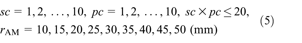

where TAM is the torque generated by the AM in joint J and T is the required torque of J.
Finally, the optimal parameters were decided with the following estimative indexes of the candidates. To keep the balance, for example, it was setup such that a solution with
Minimum number of pieces of PEAs;
Maximum ROM;
Larger margin (100 × (
Balance between
Optimization of hybrid actuation: selection strategy of actuators in joints
Taking into consideration the results of the drop impact test and the required number of pieces of PEAs, that is, the weight of the AM with the PEAs including the pulley and accessory, a decision was made in each joint about whether the AM configured in the previous section was employed using the dynamic simulation platform. If the AM was calculated to be unfit for a certain joint because of such a consideration, the motor was used in place of the AM for the joint. In this article, to select the weight of the AM, 0.067 kg, which equaled the weight of one motor, was set as a single criterion for the judgment. In this way, the two-link, 4-DOF prosthetic arm model was configured. As a result, whether an ADL-independent configuration could be acquired could be investigated.
Reproducing of ADL motion with prototype
Based on the configurations acquired using the dynamic simulation platform, a prototype was built and tested for a trajectory reproducing the experiment in order to explore its feasibility in daily living.
Results
Drop impact test
The results of the evaluation indexes described in subsection “Drop impact test” of section “Methods” are shown in Figures 6 and 7. The waveform was made using the average values for 10 times of measurement. In the waveform shown in Figure 6, the data were smoothed using a moving average of 10 points and three repetitions for visibility. Here, measured negative values, which meant a tensile force, were due to the effect of load cell inertia in the force gauge. The average values of raw data were used in Figure 7 too.

Waveform for 0.5 s after collision: (a) test under a condition that the collided weight = 0.98 N and air pressure of PEAs = 0.1 MPa; (b) 0.98 N and 0.2 MPa; (c) 1.96 N and 0.1 MPa; and (d) 1.96 N and 0.2 MPa.

Evaluation indexes in impact test: (a) first peak of impact force for 0.5 s, (b) second peak of impact force for 0.5 s, (c) time from collision to second peak, and (d) average impact difference value for 0.4 s.
Link model simulation and AM optimization
The results of the simulation for four ADL motions are shown in Figure 8 and Table 2. The required joint angle
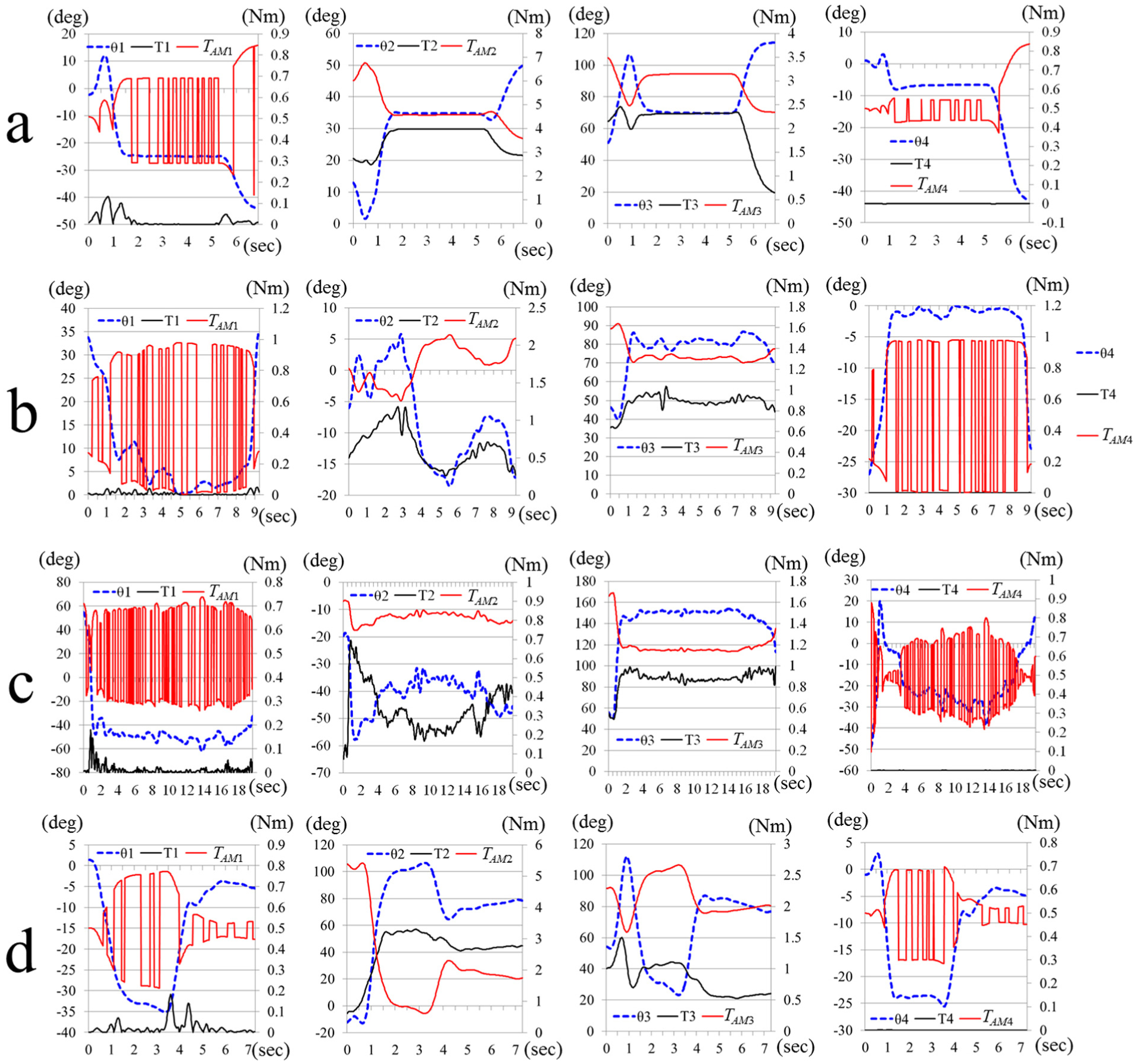
Required joint angle θ, torque T, and enabled torque TAM of AM with PEAs: (a) θ, T, and TAM in drinking motion; (b) motion of putting on socks; (c) tying motion; and (d) hanging motion. Due to the failure combination, TAM2 falls well below T2 in J2.
Configurations for AM with PEAs in four ADL motions.
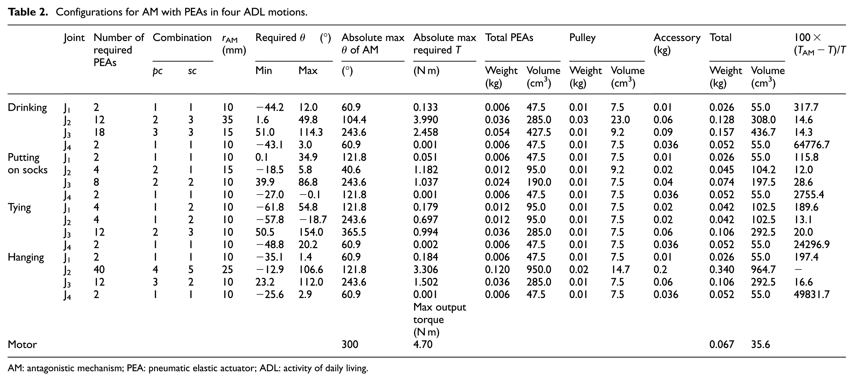
AM: antagonistic mechanism; PEA: pneumatic elastic actuator; ADL: activity of daily living.
Optimization of hybrid actuation: consideration of actuator configuration
The configuration of two types of actuators for the arm was decided based on the results of the drop impact test and simulation. At first, essentially, the shoulder-PEA-elbow-PEA (SP-EP), shoulder-PEA-elbow-motor (SP-EM), and shoulder-motor-elbow-PEA (SM-EP) showed better impact absorption than shoulder-motor-elbow-motor (SM-EM) under all conditions of air pressure and weight of collision, as shown in Figures 6 and 7. Moreover, in comparison between SP-EM and SM-EP, SM-EP was considered to have better absorption because of smaller peak values, longer time to peak, and smaller average impact difference, which means lower vibration. Therefore, it is clear that the AM with PEAs in the elbow is effective. However, this is considered to be because of the collision point on the forearm link, LF, was closer to the AM in the elbow. Therefore, the impact to the shoulder was decreased. For achieving softness of the two-link, 4-DOF arm as a whole, either shoulder, J2, or elbow, J3, should employ the AM against a disturbance in the direction of gravitational force, as shown in Figure 4(c) and the drop impact test results.
On the other hand, the simulation results revealed the disadvantages of the AM. First, the number of PEAs in the AM for each ADL motion was various. The AM of J2 could not meet the requirement in the hanging motion as described in previous section. On another front, a lot of PEAs were required in J3 for the elbow; more than J2 in the remaining three motions. Above all, the AM of J3 in the drinking motion was heavier than the weight of two motors, 0.134 kg. Therefore, considering the difference of results between the impact absorption and the weight between the AM and motor, the motor was considered to be realistically suitable for J2 in the hanging motion and for J3 in the drinking motions.
Second, J1 and J4 did not require a large torque and ROM, that is, a lot of PEAs. Comparing the AM with one motor with respect to weight and volume, there is not much difference between the two types of actuators relative to the situation of J2 and J3 as shown in Table 2. Therefore, the PEAs with an AM were also employed in J1 and J4, in all ADL motions. The above results in the actuator configuration for each ADL motion were rounded up in Table 3.
Actuator configuration of the arm for each ADL.
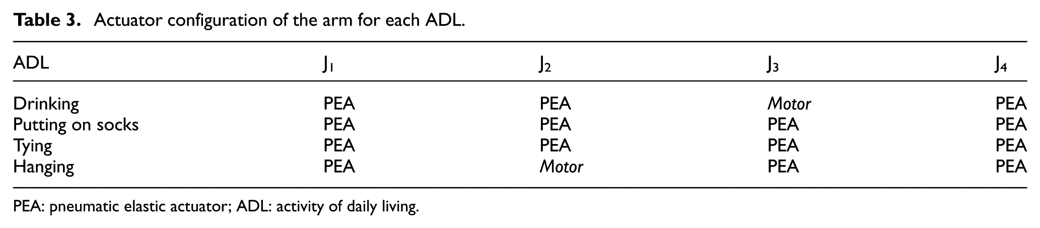
PEA: pneumatic elastic actuator; ADL: activity of daily living.
Reproducing of ADL motion with prototype
Based on the configurations in Table 3, a prototype was built and used for a trajectory reproducing the experiment in order to explore its feasibility in daily living. In this article, the objective motion for the reproduction was set to the drinking motion, and adapting all ADL motions is a future objective. Moreover, in all ADLs, including the drinking motion in Figure 8, the rotational direction change that is, on-and-off of the activation for the PEAs in J1 and J4 was often repeated every minute in the simulation. The PEAs are considered to be difficult to control for such behavior due to their hysteresis characteristics and low reaction speed. Moreover, J1 and J4 are insulated from the influence of gravity, that is, the weight of a collision object comparing J2 and J3. Therefore, in this article, we give priority to validating the feasibility of a lightweight shoulder prosthetic arm with hybrid actuation, a simplified prototype where the AM with PEAs was changed to the motor in J1 and J4 as shown in Table 4. Prototyping, which fully follows the configuration in Table 3, and building the control aspect adaptive to the configuration will be addressed in another paper.
Actuator configuration for the simplified prototype for drinking motion.

ADL: activity of daily living.
The prototype was designed and built as shown in Figures 9 and 10. The body surface data of the subject were used for a decision of the dimension and shape of the prototype including the two-link, 4-DOF arm, shoulder socket fitting the subject’s shoulder, and 1-DOF hand performing bottle grasping. The hand was specialized for grasping a bottle for simplicity and lightness using the data as shown in Figure 9(a). The motor of J3 was placed at a proximal part in the upper arm for decreasing its weight’s influence on the J2, and it drove J3 with a belt pulley as shown in Figure 9(b). The whole weight of the prototype arm including actuators was 0.776 kg, as shown in Figure 10(a). In this article, a backpack system, which could decrease the fatigue of user’s lower back by transferring the weight of the distal arm to the proximal trunk, was employed,
49
and the 12 PEAs of J2 and the servo motor which was employed for J5 was set in the backpack using remote actuations with flexible Bowden cables as shown in Figure 10. By transferring the PEAs for AM to the backpack, the space for the installation could be ensured, and multiple actuators could be embedded by connecting them with

Design of prototype. (a) 3D model of socket and 1-DOF hand. The hand was designed to generate a grasping force of more than 100 N, and only the thumb was set to rotate around J5. (b) Prototype of shoulder prosthesis. The prototype was offset 135 mm from the intact arm in the Y-direction as described in subsection “Link model simulation” of section “Methods.”

Prototype worn by subject: (a) the weight of the hand, forearm, upper arm, socket, and backpack was 0.102, 0.158, 0.516, 0.244, and 0.924 kg, respectively; (b) lateral view of prototype; and (c) back view of prototype.
In the AM of J2, an open-loop proportional controller was used to regulate the air pressure for PEAs, and gain desired θ2. Although the blue pathway made by modifying the hand tracking data in Figure 4(e) was used to calculate the
The results of the experiment are shown in Figure 11. An error between the hand position in the trajectory and the six points of the target was caused by the influence of a minor deviation of the subject’s posture and a slippage of the socket when reproducing the drinking motion, as observed in Figure 11. Thus, the hand and mouth position were required to change slightly with the trunk and neck motions of the subject for grasping at point 5 and the drinking at point 6 in order to ensure the execution of the ADL motion. Finally, the prototype could move the grasped bottled water of 0.25 kg (including the weight of the motion tracking marker that was mounted at the upper part of the bottle) to the mouth.

Experiment of drinking motion: (a) Point 1 (start point) in the motion in Figure 4(f); (b) Point 2 (reaching); (c) Point 3 (reaching); (d) Point 4 (reaching); (e) Point 5 (grasping and unscrewing the top); (f) Point 6 (drinking); and (g) measured trajectory of intact hand, of prototype, and the six target points. Errors between points 1–6 and the trajectory at each point are 43.6, 58.0, 37.2, 19.2, 59.8, and 74.5 mm, respectively.
Discussion
At first, the joint with PEAs showed the best validity with respect to impact absorption. SP-EP showed not only smaller first and second peak values and a longer time from collision to the second peak, but also smooth and low-vibration waveforms in Figures 6 and 7. This slow transmission of the force provides a possibility for additional development, for instance, reaction with some control strategy. In general, SM-EP showed better index values than SP-EM. This is because that collision point is closer to the AM joint with PEAs in SM-EP combination, as described in subsection “Optimization of hybrid actuation: consideration of actuator configuration” of section “Results.” Therefore, AM should be used in either a shoulder or elbow to guarantee preferential softness.
In the simulation, the decided configurations of PEAs in the AM of each joint for each ADL motion, that is, ROM and torque, were not same. Moreover, the layout of PEAs and AM/motor for each joint in the arm was also different between all ADLs. At first, the hanging trajectory was different from the other three motions in terms of more distance and a higher reaching motion as shown in Figure 3. This means needing a larger angle of the shoulder, J2, for the hanging motion. Moreover, an AM with PEAs joint that meets the condition in equations (5) and (6) could not be acquired. That means more than 40 PEAs will be necessary, which is impractical. Therefore, the AM joint was confirmed to be inappropriate for such motion because the joint angle, that is, the PEAs contraction is larger, and output is smaller as shown in equation (1). Therefore, too many PEAs were necessary. In other words, the AM shoulder joint is considered to be suitable for a working space that was lower than around the mouth from the results of drinking, tying, and putting on socks.
In the drinking motion, the shoulder J2 was small, and the elbow J3 was large, contrary to the hanging motion. This is just as valid for the motions of putting on socks and tying because subjects move their hand close to their body by folding their arm, that is, elbow, for the motion at the space close to the body. Therefore, the motor was employed for J3 in drinking. The unnecessity of the motor, that is, fewer PEAs in the AM for J3 in putting on socks and tying than drinking in spite of a larger angle is considered to be due to the lighter weight of 0.05 kg compared to 0.5 kg for the drinking bottle as described in subsection “ADL measurement” of section “Methods.” Moreover, the actuator configuration of the arm, which enables it to perform all four ADL motions simultaneously, is shown in Table 5. Basically, the greater the number of ADL motions that are intended, the more PEAs, and the bigger the total weight (kg) and volume (cm3) that is required in order to cover various joint angles, rotational directions, and torques. Hence, the motor application increases for the conformance to many ADL motions. However, in case of a similar joint angle and torque, such as the relationship between the tying motion and the putting on socks motion, the same actuator configurations are employed, as shown in Table 3. Therefore, factors such as the number of intended ADLs influencing the necessary joint angle and torque, the similarity or multiplicity between intended ADLs, and the PEA joint’s adoption, that is, prioritizing safety and softness, are considered to be in a trade-off relationship.
Actuator configuration for all four motions.

ADL: activity of daily living.
In all four ADLs, the load of J1 and J4 was lighter. This is considered to be due to immunity from the gravity force directly. Therefore, the PEAs with an AM were employed for J1 and J4 in the simulation, although the motor was used in the prototype. The difficulty of controlling PEAs with their hysteresis characteristics and low reaction speed was considered, and the vibration that occurred in J1 and J4, which resulted from rapidly switched activation of antagonist and agonist, is shown in Figure 8. In the future, the influence of the hysteresis using PEAs with an AM joint in J1 and J4 with the real machine must be investigated.
Next, the prototype two-link, 4-DOF arm with a 1-DOF hand is discussed. The weight, 0.776 kg, of this prototype arm (compressor, battery, and control unit were not included) was considered to be light in comparison to the other prosthetic arms13,28,30,32 as shown in Table 6. Moreover, because the forearm and hand had a sufficient strength for the drinking motion, it is possible to reduce the weight additionally by decreasing the thickness of the ribs in the chassis. The grasping force was approximately half of the simulated value as described previously. This is considered to be due to the cable routing and wire stretching and should be remedied in future. The hand itself could grasp the bottle of 0.5 kg. However, the arm could not convey the bottle of 0.3 kg in the experiment of drinking motion. This was influenced by a belt slippage of the joint J3 in Figure 9(b). Therefore, an improvement of the transfer mechanism could enhance the performance. The anthropomorphic hand and forearm appearance were materialized with the 3D scanner and designed so that the socket could fit the shoulder of the healthy subject. However, the deviation of the subject’s trunk posture and shoulder socket caused the trajectory error shown in Figure 11(g). A minor gap between the socket and the intact shoulder was considered to have an effect on the hand trajectory. It is necessary to improve the fixation of the socket. In the future, a meaningful challenge for the trajectory generation is to implement a method of the feedback control that can improve the precision.
Comparison of weight.

DOF: degree of freedom; CAD: computer-aided design.
Conclusion
In this article, hybridization of two different actuators, PEAs and servomotors, in combination with an AM, was employed to deal with the design problem of shoulder prostheses. A two-link, 2-DOF arm was used to test the different configuration of hybridization in a series of drop impact experiments, in terms of impact absorption. A dynamic simulation platform based on the motion data of four bimanual ADLs was established and used to obtain the required ROM and torque for each joint of the two-link, 4-DOF arm. The number of PEAs required and the dimensions of the mechanical structures for the AM were optimized using the dynamical simulation platform. According to the experiment and based on the drop impact test results and other criteria, the configuration of two types of actuators was determined, and a simplified prototype was made.
Results showed that the joints with PEAs could absorb more impact force than with motors. The ADL measurement experiments revealed that the actuator configuration of shoulder prostheses is ADL dependent. In motions requiring more distance and higher reach, such as the hanging motion, a larger angle and torque of the shoulder, J2, were necessary. Therefore, the PEAs with an AM joint were confirmed to be inappropriate for such motion. Consequently, the motor joint predominated the candidate pool, more than the PEAs, which needed a considerable number of pieces. The AM with PEAs is suitable for the motions that do not require high and distant reaching. Based on these results, a simplified shoulder prosthesis that met the ROM and torque requirements for one specific ADL was prototyped, and the trajectory of the ADL was reproduced. The prototype with the hybridization of two different actuators could reproduce the ADL motion, indicating its feasibility in daily living.
However, it is necessary to conduct further investigation. The prototype, which fully follows the optimized configuration, as shown in Tables 3 and 5, that is, the compatibility for other important ADLs motions and control for the visco-elasticity and the motion with hysteresis of PEAs, should be addressed in future.
Footnotes
Appendix 1
Academic Editor: Alicia Casals
Declaration of conflicting interests
The author(s) declared no potential conflicts of interest with respect to the research, authorship, and/or publication of this article.
Funding
The author(s) disclosed receipt of the following financial support for the research, authorship, and/or publication of this article: This work was primarily supported by the Japan Society for the Promotion of Science (JSPS) Grant-in-Aid for Scientific Research (B), Grant Number 26282160.