
Abstract
Human arms undertake most tasks in the activities of daily living (ADLs). When designing shoulder prostheses for high-level upper-limb amputees, we should consider not only how to realize high degrees of freedom under weight and shape constraints but also the user's individual task space in daily life. An appropriate mechanical structure that can make full use of state-of-the-art actuators and a scheme to optimize the structure's configuration to match users' spatial access and manipulability requirements are essential. In our previous research, a small pneumatic-actuator-driven parallel mechanism was studied as a shoulder prosthetic arm. In this paper, a systematic procedure is proposed to design the mechanism for a shoulder prosthesis considering force and spatial accessibility. This procedure includes ADL measurements to obtain the task spaces for individual subjects, indexes to evaluate the force and spatial accessibility and an optimization process based on kinematic and statics models. With this approach, the parallel mechanism was optimized for one important ADL task group, considering the trade-off between its required force and working space. Moreover, it was confirmed that the proposed design procedure could find solutions for various spatial specifications. That is, the approach could be used for individualized shoulder prosthesis design.
Keywords
1. Introduction
Human arms undertake most tasks in the activities of daily living (ADLs). A shoulder prosthesis might lead to a great improvement in the quality of the ADLs for high-level upper-limb amputees. A shoulder prosthetic system is a typical and extreme case of a motor-sensory substitution for an amputee. Compared with forearm, upper-arm and lower-limb prostheses, a shoulder prosthesis has to provide its user with more assistance. Thus, it requires higher degrees of freedom (DOFs), which require a large number of actuators. In a case where each actuator is heavy, this would result in a large size and a heavy weight. Moreover, the spatial accessibility relies almost completely on the DOFs of the shoulder prosthesis because the residual stump is usually too small to provide mobility to the prosthesis.
In recent years, various studies have been conducted on developing prostheses and robot manipulators that could be adapted to shoulder amputees. These devices have diverse functionality and high performance [1-3]. For example, a five-DOF prosthetic arm driven by DC motors with gearheads has been built where the mechanism of the arm could duplicate the human radius and ulna [4]. In addition, an artificial arm with a spherical ultrasonic motor has been developed, which has three DOFs like a human arm joint and can be driven silently without gears [5].
Most of these prostheses are supported by metal frames or parts and are driven by motors, with a total weight of around 2–3kg. According to a questionnaire given to amputees, it is desirable that the weight of a prosthetic arm be less than 0.9kg [6]. Adopting light elastic pneumatic actuators is a way of saving weight. Some researchers have developed devices with pneumatic actuators that could be used as manipulator arms [7], [8]. However, they are not for prosthetic use. In our previous studies [9], [10], we proposed a small pneumatic-actuator-driven parallel mechanism as a shoulder prosthetic arm.
Two of the major advantages of pneumatic actuators are their viscoelasticity and back-drivability, which are expected to contribute to safety against collisions or contact between the prosthetic shoulder and its environment in daily living use. Furthermore, the parallel mechanism compensated for the lack of rigidity caused by the use of soft actuators. However, it is still necessary to determine a design method for the parallel mechanism that considers the force and spatial accessibility under the constraints of weight and shape (its appearance should be similar to that of a human arm). To the best of our knowledge, there has been no research on prosthesis design focusing on spatial accessibility and its trade-off with the required driving force, considering real ADLs.
In this paper, a systematic procedure is proposed to design the mechanism for a shoulder prosthesis considering the force and spatial accessibility. This procedure includes the measurement of ADLs to obtain the task spaces for individual subjects, indexes to evaluate the force and spatial accessibility, and an optimization process based on kinematic and statics models.
The paper is organized as follows. In Section 2, an overview of the shoulder prosthesis design procedure is given. Section 3 shows the components of the design process. Some experimental results are shown in Section 4, with a discussion given in Section 5. Section 6 concludes this paper and describes future work.
2. Outline of design procedure
In this section, to increase the understandability and convenience of the explanation, the mechanical structure of the shoulder prosthetic arm is first described. Then, the design constraints and design variables are introduced, followed by an outline of the design approach.
2.1 Basic structure of shoulder prosthesis
Figure 1(a) shows the appearance and prototype of the shoulder prosthesis developed in our previous study [9], [10]. The arm is composed of three segments, as seen in Figure 1(b), (c), and each segment is connected to the next one in the series at an angle, which is called the mounting angle. These mounting angles are labelled as ϕ(ϕxi,ϕyi), (i = 1, 2, 3), for segments 1, 2 and 3, respectively. Here, the state of the arm before actuator activation is defined as stand-by state. In [9] and [10], three segments were initially aligned in a straight line, as shown in Figure 1(a), (c), i.e., the mounting angle ϕ was set to zero. However, in this study the initial mounting angles were investigated for better spatial accessibility. The results were then compared with the results of our previous research, in which the lengths of segments 1, 2, 3 and ϕ were set to 150, 170, 200mm and 0 degrees, respectively (this configuration is defined as the benchmark configuration), as shown in Figure 1(c) and (d).

Arm mechanism and geometry (unit: mm in (d))
In Figure 1(e), the arm's inner structure is illustrated. Each segment contains a parallel link mechanism with pneumatic actuators. Segment 1 links two disks, called base 1 (grey) and moving platform 1 (blue), with backbone 1 and three pneumatic actuator sets, which consist of two actuators, connected in parallel, per set. Thus, segment 1 has a total of six actuators. Backbone 1 is placed in the centre of base 1 and joined to the centre of moving platform 1 using two passive rotational joints, as shown in Figure 1(f). Backbone 1 is presumed to be a compression spring that can only move in a longitudinal direction. This enables moving platform 1 to move along the longitudinal direction of backbone 1 and turn the joint of moving platform 1 and backbone 1 around. Segment 2 has the same structure as that of segment 1, except that half the actuators are used, because the required force of segment 2 is assumed to be less than that of segment 1. Segment 3 comprises a robot hand, actuators for realizing hand grasping and backbone 3 fixed to the centre of base 3 (grey) of segment 3.
A pneumatic actuator (PM-10P, Squse Inc.: 0.003kg, 100 N, average shrinkage ratio: 30%) and an air compressor (MP-2-C, Squse Inc.: 0.18 kg, 0.4 MPa) are also proposed. Our estimation of the weight of the entire system is 1.982kg (arm without hand: 0.492kg, hand: 0.25kg, backpack system (See Figure 1(a)) with all accessories: 1.24kg) based on a CAD calculation, the details of which are listed in Table 1. As a guide, in the previous study, the prototype arm's weight without the hand, as shown in Figure 1(a), was 0.38kg.
Estimation of component weights
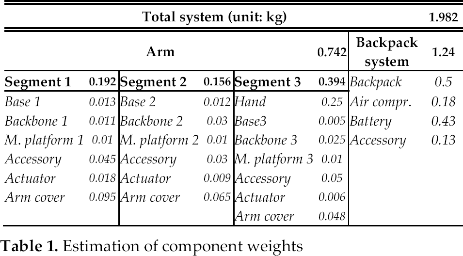
One may question the fact that this weight is far greater than the desired one (0.9kg) reported by [6], as discussed in Section 1. We argue that the total weight of the arm and hand is only 0.742kg, while the backpack contains the remaining weight, i.e., 1.24kg. From the viewpoint of both statics and dynamics, weight proximal to the body centre is a lesser burden than a distal weight. Since the backpack is to be tightly and securely attached to users' back, i.e., it should be very close to the centre of the body, it is reasonable to not count the weight contained in the backpack as the weight of the prosthetic arm.
2.2 Constraints, specification and design variables
2.2.1 Design constraints
The design constraints can be listed as follows. Most of these have been mentioned in the preceding sections.
The maximum force of each small elastic pneumatic actuator is 100N.
A parallel link mechanism was employed for each segment to compensate for the lack of rigidity.
The weight of the prosthetic arm and robot hand (except for the battery and air compressor) should be under 0.9kg.
The appearance of the prosthetic arm should meet cosmetic requirements and the structure should be somewhat anthropomorphic.
2.2.2 Specifications
The working space and payload of the prosthetic arm were specified as follows.
Because the prosthesis is designed for use in daily life, the working space of the prosthetic arm should meet the individual user's target space. In this study, rather than the users' occupational requirements, we determined the target space based on ADLs. First, based on a functional independence measure (FIM) [11] evaluation sheet, which is in widespread clinical use, we chose three types of ADLs according to their importance:
eating from a lunch box
drinking a bottle of water
brushing teeth
The hand trajectory during these motions was measured using a motion capture system, by which the ADL target space, called the ADLA (ADL area), was identified to evaluate the spatial accessibility. The details of this measurement and analysis will be given in Section 3.
Moreover, the payload set up in these cases was as follows.
10N (considering the weights of the hand [0.25kg] and lunch box [around 0.7kg] as static forces)
2.2.3 Design variables
The objective of the design process is to find suitable values for the following two design variables to meet the specifications under constraints.
The stand-by state (this is determined by mounting angle ϕ as described in Section 2.1). Note that the stand-by state can also be adjusted by using biasing spacers to allow the alignment of the actuators, as shown in [10].
The configuration of the arm (physical dimensions such as the length, outside diameter and mounting angle of the arm mechanism)
2.3 Design approach
The optimization-based design approach includes four steps.
Measuring the typical ADL to identify the target space for a specific individual user.
Generating numerous candidates for the design variables, under the constraints described in Section 2.2.
Calculating the values for a set of indexes reflecting the spatial accessibility, output performance and manipulability, based on kinematics and statics, for all of the candidates. The indexes and models will be explained in Sections 3.2 and 3.3, respectively.
Choosing the optimal configuration using a set of selection criteria, which will be described in Section 3.4 (in a case where no candidate meets the criteria, go to Step 2).
3. Important components for design process
3.1 Determining task spaces for prosthetic arm
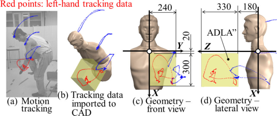
In this study, a motion tracking system (OptiTrack) was employed to measure the hand trajectory during the specified ADL. The experiment to measure the ADL of eating from a lunch box is shown in Figure 2(a). Reflective markers were attached to the head, neck, shoulders, elbows and hands. All of the ADL tracking was conducted at 60Hz and the times for tracking the three types of ADL mentioned in Section 2.2.2 were 20 seconds, 1 minute and 2 minutes, respectively.

Motion tracking and 3D human data (unit: mm)
A 3D model of a human and coordinate system, as shown in Figure 2(b), was employed for illustration purposes. The model utilized 50th percentile CAD data from a Japanese male who was 167.0cm tall. We set the origin O (0, 0, 0) at the intersection of the horizontal plane (X = 0) and the coronal plane (Z = 0), passing through the acromion with the median sagittal plane (Y = 0). The positions of the acromion were assumed to be (0, ±170, 0).
3.1.1 Target space for 3 types of ADL–ADLA
The human subject in the experiment was 165.0cm tall and was sinistral. Therefore, the left hand of the subject was tracked during the three types of ADL.
Figures 3(a)–(c) show the data for the three types of ADL. Moreover, the green box that covers the hand trajectory (red colour) in Figure 3(d) was identified as the target space (ADLA). The dimensions of ADLA for the human subject are shown in Figures 3(f) and (g).

Setting up ADLA (unit: mm)
3.1.2 Target space for right hand transformed from ADLA to test adaptability of design approach–ADLA'
Another target space, ADLA‘, symmetric to ADLA with respect to the XZ-plane, was acquired by symmetric transformation, as shown in Figure 4. This corresponds to the right-hand target space of the same subject. This target space could be used to test the adaptability of the proposed design approach.

ADLA' (unit: mm)
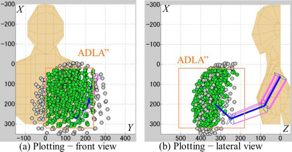
3.1.3 Target space for putting on socks–ADLA″
The ADL of putting on socks was also measured to acquire a target space (ADLA″) (Figure 5). This target space can be used to test to what extent a prosthetic arm designed for a group of ADLs could adapt to a very different type of ADL. The hand trajectory for putting on socks is certainly different from that for eating and brushing teeth, without the physical dimension of the prosthetic arm.
ADLA″ of putting on socks (unit: mm)
3.2 Kinematics and statics models
A kinematics model of the arm structure was developed to analyse the behaviour of the hand and its working space. The coordinate system of the arm is shown in Figure 6. The O-XYZ is the world coordinate system, as in Figures 1, 2 and 3. The local coordinate system OB1-x1y1z1 is set up at the centre of base 1, with the z1-axis directed along backbone 1. The local coordinate systems OB2-x2y2z2 and OB3-x3y1z3 are placed at the centres of base 2 and base 3, respectively. The contact points of the pneumatic actuators to the base and moving platform are B1i, B2i and M1i, M2i (i = 1, 2, 3), which were aligned equiangularly along the peripheries of circles with radii rBj and rMj (j = 1, 2), as shown in Figure 6(a). Bj1 and Mj1 are in each local xj-axis direction (j = 1, 2). Backbone 3 is placed at OB3 along the z3-axis. At this time, the lengths of backbones 1, 2 and 3, and each actuator are lBi, l1i and l2i (i = 1, 2, 3), respectively. l1i includes two parallel actuators, as shown in Figure 1(e).

Motion of segments 1, 2 and 3
As noted before in Figure 1(b), segment 1 is mounted rotating by (ϕx1, ϕy1) with respect to the human trunk (i.e., O-XYZ) as shown in Figures 1(b), 1(c) and 6(a). In addition, segments 2 and 3 are mounted rotating by (ϕx2, ϕy2) and (ϕx3, ϕy3) with respect to segment 1 (Ob1-x1y1z1) and 2 (OB2-x2y2z2), respectively. When the actuators are activated as shown in Figure 6(b), their lengths change (expressed discretely: l1i and l2i become l1i ‘and l2i’, i = 1, 2, 3). Thus, lB1, lB2, B2i and M1i, M2i (i = 1, 2, 3) are converted into lB1, lB2, B2i ‘and B1i’, B2i‘. Moreover, two passive joints (joint 1 of moving platform 1 and joint 2 of moving platform 2, see Figure 1(e)) rotate by θxi and θyi (i = 1, 2), respectively. Let the rotation matrix of the mounting angles of segments 1, 2 and 3, and the matrix of joints 1 and 2, be Rϕ1, Rϕ2, Rϕ3 and Rϕ1, Rϕ2. In addition, let the coordinate of the hand position, i.e., backbone 3's end tip, be P(x, y, z). Then the length of each actuator l1i’ and l2i ‘(i = 1, 2, 3) and P can be framed as follows.

Here, the design variables, as described in Section 2.2, are summarized as follows (see Figure 6).

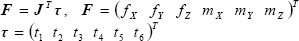
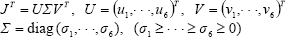
In order to evaluate the required force of the prosthetic arm's end tip, i.e., that of one of the actuators, the statics are calculated. By using the virtual work principle, the relation between the generated force of hand position P, F and that of each actuator, τ, is acquired as follows. Here, fX, Y, Z and mX, Y, Z are forces in the X-, Y- and Z-axis directions and moments around the X, Y and Z axes of the world coordinate system, respectively. τ(t1, …, t6) are each actuator's generative forces. J is the Jacobian matrix of the arm structure.
In this study, the dynamical characteristics were not considered in the evaluation and simulation. However, this does not mean that dynamical factors are not important for the prosthetic arm. On the contrary, even for the ADLs investigated in this study, such as tooth brushing, without taking the inertia of the segments and viscoelasticity of the actuators into consideration, it is difficult to realize even that kind of periodical motion. However, under the assumption that the motion of the amputees would be slower than that of normal people, without considering the dynamical factors, the design process would be much simpler. Certainly, after the design and manufacture of the prosthetic arm, the dynamical characteristics should be investigated using experiments.
3.3 Evaluation indexes
Because of the constraints, a design that meets the specifications completely could not be expected. Therefore, defining indexes to find optimal or sub-optimal designs is necessary. According to the aforementioned analysis, two types of indexes should be considered.
Spatial accessibility (using kinematics, this is later expressed by three indexes)
Output performance and manipulability (by statics)
Moreover, to deal with the multiple-criteria optimization problem, rather than selecting the best solution using the weighted sum of multiple criteria, the lower bound of each criterion was set up to explore the solutions that meet multiple least requirements. The lower bound was given as a percentile-based threshold, which will be explained in Section 3.4.
3.3.1 Spatial accessibility
In order to obtain the index of spatial accessibility, the working space had to be calculated. The design variables were first discretized. Then the coordinates of the end effector
N: Number of points
In addition, the evaluation indexes of spatial accessibility using N were described as follows.
C: distance between centre of Σ
D: Distribution of Σ
E: Entropy of Σ
Here, C represents a fitting measure for the working space, i.e., Σ
D in ADLA
Here, E represents the information entropy of Σ
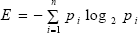
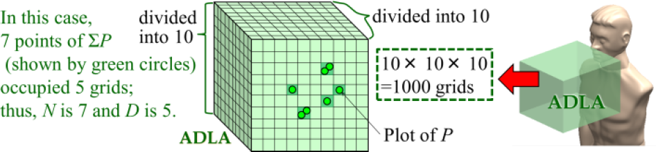
Here, n and pi correspond to the total number of grids in ADLA and the ratio of the number of end tip points

Specific example of E
The spatial accessibility of the shoulder prosthesis could be evaluated using D and E, together with C.
3.3.2 Static evaluation
3.3.2.1 Required force
By using (3), the required forces can be calculated. As noted in Section 2.2, on the basis of a hand weight of 0.25kg and a lunch box weight of around 0.7kg, we suppose that an external force of 10N (1kg) acts on the hand position
F1: Maximum required force per actuator of segment 1, which has six actuators, at Σ
F2. Maximum required force per actuator of segment 2, which has three actuators, at Σ
3.3.2.2 Manipulability
The condition number is based on a singular value of matrix
By using the singular value, we use the following condition number w as the estimation index element based on the manipulability ellipsoid [14]:

w is the ratio of the maximum radius to the minimum of the ellipsoid. When this value is larger than 1 and closer to 1, the ellipsoid shape is closer to spherical. Thus, w is an index that stands for the directional uniformity of the manipulability ellipsoid.
To evaluate different aspects of the system, the evaluation index of manipulability (M) was adapted using (6) as follows.
M: 3rd quartile of w of points
Given the function of the manipulator, it is desirable that the forces that could be generated at
Because of the possibility of very bad manipulability in some postures, it is necessary to specify the lower bound for the worst manipulability that could be allowed.
3.4 Selection of optimal configuration
Using the design variables in (2), the optimal configuration is selected in an exploratory trial. First, the evaluation indexes C, D, E, F12 and M of the benchmark configuration for ADLA are confirmed as a standard for comparison. The variables of the benchmark configuration, as shown in Figure 1(d), are summarized in (7). As previously noted, angle ϕ is set to zero.
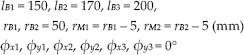
Next, calculations that roughly change lBi (i = 1, 2, 3) and rBj (J = 1, 2) in (2) compared to (7) are performed to examine the trade-off between the required force and the working space of the arm for ADLA. Based on the results, rBj and rMj (j = 1, 2) are selected. The variables are changed as follows.

Finally, by using variables (9) and the above selected rBj and rMj, the indexes of all the candidate configurations are calculated and the optimal configurations are selected using the evaluation indexes in Section 3.3 for ADLA, ADLA' and ADLA″. A total number of 32 × 44 × 33 = 62,208 candidate configurations can be obtained.

Here, thresholds were determined as follows to reflect the constraints from spatial accessibility.
C: Lower than 0.2th percentile
D: Higher than 99.8th percentile
E: Higher than 99.8th percentile
Thresholds were determined as follows to reflect the constraints from the required forces and manipulability.
F1, E2 and M: Lower than 40th percentile
Because F1 and F2 were considered to some extent in the above-mentioned examination of the trade-off between the required force and the working space, the restraint conditions for F1 and F2 with M are set up weakly, while those for C, D and E are set up strongly. The configuration that meets the aforementioned conditions would be considered the prospective solution. The optimization is performed with the flow as in Section 2.3.
3.5 Difference between roles of spatial accessibility indexes D and E
The evaluation indexes for the spatial accessibility, D and E, look the same. However, they have different properties. As previously described, D and E represent the distribution broadening and uniformity of Σ
4. Results
4.1 Benchmark configuration
A plot of

Plotting benchmark configuration and optimal one for ADLA and ADLA' (unit: mm)
Values of evaluation indexes

4.2 Examining trade-off between force and working space
A total of 33 × 52 = 675 configurations, as shown in (8), can be made and these are identified as No. 1 - No. 675, as listed in Table 3. The evaluation indexes D, F1 and F2 were calculated for all of the combinations, as shown in Figure 10, where the horizontal axis represents the ID of the combination.

Trade-off between force and working space
IDs of 675 combinations (unit: mm)
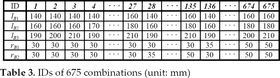
In Figure 10, two characteristic cycles can be confirmed. The first is a cycle consisting of sets of 27 IDs, which corresponds to an increase in rB2. In this cycle, F2 decreases greatly. The other is a cycle consisting of sets of 135 IDs, which corresponds to an increase in rB1. Here, F1 decreases greatly. Moreover, D decreases gradually in tandem with rB2 and especially with rB1. F1 and F2 increase and decrease minutely as a result of the effects of lB1, lB2 and lB3, but these seem to be small compared to rB1 and rB2. There are a few F1, F2 = 0, where D = 0, because the sum of lB1, lB2 and lB3 is too long to fit any plotting point
4.3 Optimal configuration
Using the optimal rB = 35 and rM = 30 mm, the indexes of all the candidate configurations are calculated and one configuration is selected with the threshold values based on the indexes.
A comparison of the evaluation indexes and plotting in the ADLA between the optimal configuration and the benchmark one is presented in Table 2 and Figures 9(a) and (b). In Figure 9, the posture of each illustrated arm is the stand-by state (much of the same is true in Figure 11 and 14). As listed in Table 2, all of the indexes except F1 and F2 are improved considerably. The F1 and F2 of the optimal configuration are caused by a smaller moment arm, rB1,2 and rM1,2. In Figure 9, Σ
Optimizing putting on socks in ADLA″ (unit: mm)
The optimal configuration of ADLA' is compared to that for ADLA in Table 2 and Figures 9(b) and (c).
The thresholds of ADLA ‘are the same as in the case of ADLA. In Figure 9(c), it can be confirmed that this configuration corresponds to ADLA’ by comparing the optimal configuration in ADLA.
4.4 Adjusting mounting angle ϕ for ADLA″
For a completely different task, putting on socks, the location of task space ADLA″ changed significantly. Taking the mounting angle as the design variable and keeping length l and radius r fixed to the same values as the optimal ADLA configuration presented in Table 2, the design approach finds the solution expressed in Table 4 and the plot Σ
Design variables and indexes of optimal configuration for putting on socks in ADLA'

4.5 Validation of differences between functions of D and E
In order to examine the relationship between D and E, all of the 62,208 candidate configurations were sorted in descending order of D and the upper 1000 configurations were extracted. Then, the corresponding E was compared with D in Figure 12.

Upper 1000 D and corresponding E
In Figure 12, the horizontal axis represents the ID of the configuration. E decreases while vibrating as D gradually decreases. On this occasion, the trends for D and E are seen in several locations, such as No. 285 and No. 810. The details and close-ups of lateral view plots in ADLA are listed in Table 5 and shown in Figure 13, respectively. Comparing these two IDs, in Figure 13(a), the plotting for No. 285 seems to be massed around area A, while the density of the plotting is lower around area B, although D can be counted. In contrast, that for No. 810 is widespread, although smaller interspaces are found. This shows that the effect of E is reflected, D and E are functioning discretely and this relationship can be confirmed to resemble the one between Cases III and IV in Figure 8.
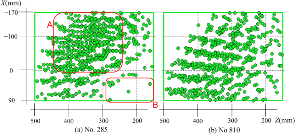
Lateral view plots for No. 285 and No. 810

Threshold difference in plotting (unit: mm)
E, D and design variables for No. 285 and No. 810

5. Discussion
The length l, radius r and mounting angle ϕ in the stand-by state were set up as the design variables. Basically, l and r govern the payload and size of the working space, while ϕ affects its location. Therefore, these variables played different roles for the prosthetic arm.
In this paper, a portion of the standard ADLs, including eating from a lunch box, based on the experimental measurements, is used as ADLA for the evaluation. It was confirmed that our proposed design procedure could correspond to a change in ADLA, as shown in Sections 4.3 and 4.4. Thus, if the ADLA to meet the actual needs of an amputee is re-measured and re-analysed, a new optimal model arm that fits the task space of an individual user can be carefully developed.
As shown in Figure 9, the working space of this parallel mechanism acquired a parasol-like form. In other words, the ranges for the working space in the X- and Y-axis directions are large, while that for the Z axis is small, as shown in Figure 9. Moreover, in the literature, similar ranges for the working space of a robotic device are seen [15]. Therefore, it is important to optimize the mounting angle, ϕxi and ϕyi, and adjust the posture of the working space to fit the ADLA, i.e., the individual user's frequently accessed areas in daily living. It is especially important to make effective use of the longitudinal ranges of the working space.
In addition, it is rational to move the working space of the shoulder prosthesis toward the ADLA, so as to enhance the coverage of this area by the prosthesis, by using C and the other special evaluation indexes, along with the modification of l, r and ϕ to adapt to the changes in ADLA, as a result of any possible specific requirements from users, as shown in the experiment results. Moreover, the introduction of the mounting angle of the segments resulted in a reduction in the actuator's required force because of a shortening of the actual distance from the base of the arm to the end tip position
The design variables, lB1,2,3, rB1,2 and rM1,2, which correspond to the length and thickness of a human limb, are used for optimizing. The exploration of the trade-off between the force and the working space in Section 4.2 showed that rB1,2 have a large effect on the required force of the actuator and the working space. Given the goal of making the prosthesis look as much like a human limb as possible, the thickness is limited to some extent. Thus, smaller values of rB1,2 and rM1,2 are advantageous, both for designing an anthropomorphic arm and to obtain a wider working space. Moreover, the resultant optimal configuration arm shows possibilities for further reducing the moment arm, rB1,2 and rM1,2, because of the margins of F1 and F2, as listed in Table 2. We must review this matter.
In Section 4.5, it was confirmed that D and E were both functioning. The l of No. 810 had a shorter base (lB1) and longer terminal (lB2, lB3) than No. 285. Therefore, the radius of action is larger and the plotting is more widespread. Although the l is longer and the working space is more widespread, a much larger shrinkage ratio is needed for the pneumatic actuator in order to match the working space to ADLA. Thus, a much longer l is impossible.
Although it may seem that the thresholds used in Sections 3.4 and 4.3 place too much emphasis on evaluation indexes C, D and E, here, another optimization is performed by using thresholds that might appear well balanced, as follows.
D, E: Higher than 94th percentile
C, F1, F2, M: Lower than 6th percentile
Comparisons of the results using the thresholds in Section 3.4 (primary optimal configuration) and the abovementioned well-balanced ones are presented in Table 6 and Figure 14. The latter thresholds surpass the former for F1, F2 and M. However, the balance of the plotting does not seem to be good; the former plotting for the ADLA matches the area better. Moreover, the former F1 and F2 are within the tolerance level, i.e., both are much lower than their maximum forces (100N). Therefore, we believe the former thresholds are appropriate.
Threshold difference in indexes

Furthermore, in the custom-made design for an individual user, three aspects could be taken into consideration. The first is the standard ADL considered at this time. The second aspect is the occupational requirement. If one motion is especially important for a specific user's occupation, then that motion should also be taken into consideration. The third aspect is the feasibility of the mechanical design. Because of the structural complexity of human upper limbs, the portability required and the cost limitation, it is difficult to realize shoulder prostheses with the same DOFs and ROM (range of motion) as a human humerus. Therefore, some important ADLs (for example, toilet self-care [16]) that could be performed by the healthy side might be passed over. There is a trade-off between convenience and feasibility. Considering the three aspects, the captured data of the motions could be superimposed to configure the ADLA.
Finally, the optimal configuration arm is selected by using the thresholds that emphasize the space accessibility. However, we believe that there is room to improve the working space and it is necessary to further explore this. The following directions will be explored in a future study: 1) pursuing shorter rB1,2 and rM1,2 and 2) re-analysing and re-evaluating the arm after adding new design parameters (for example, the new mounting angle ϕz1,2,3 in Figures 1(b) and (c)) to enable better combinations.
The adaptability of the design approach for ADLA ‘(right-handed version of ADLA) and ADLA″ (the target space for putting on socks) was tested. ADLA and ADLA’ correspond to the cases of designing for the dominant and non-dominant arm versions of the same task. ADLA″ corresponds to a completely different ADL task. The design approach could find solutions for all the different target spaces. In the case of ADLA″, the physical dimensions of the prosthetic arm were fixed, while various mounting angles were explored. This means the prosthetic arm could deal with different types of ADLs simply by adjusting biasing spacers. Certainly, this needs further investigation.
6. Conclusion
We proposed a systematic procedure to design a shoulder prosthesis considering the force and spatial characteristics by using real motion tracking. The evaluation indexes for evaluating the required force and the spatial accessibility of a shoulder prosthesis were presented. In addition, the effects of the configuration of the segments, including the mounting angle, on the working space and the force of the shoulder prosthesis were confirmed.
The most desirable ADLA for an individual user might be different because of individual differences related to their tasks, physical body dimensions and daily lifestyle. Thus, the approach to determine the configuration is more significant than the optimal configuration itself. Therefore, the results of this study will be helpful in the design process for shoulder prostheses with functional restraint elements. In the near future, new methods to improve the spatial accessibility and force should be devised and investigated. Moreover, in order to fully show the possibilities of the mechanical structure as a shoulder prosthesis, the control and human machine interface for the pneumatic actuator driving the mechanism need further work. Furthermore, it is important to develop new real prostheses to confirm our latest design.
Footnotes
7. Acknowledgments
This work was primarily supported by JSPS KAKENHI Grant Number 25922011 and partially supported by the US International Technology Center.