
Abstract
The brake of winch is to prevent the occurrence of reverse slipping at working time. Based on the analysis of two types of brake, this article establishes the relationship model of the brake force and the angle of the screw thread on the brake shaft and builds the model of the relationship of the brake force and the height of the cone and found that the brake force is the largest when the angle of the screw is 45°. Also found that the brake force increases with the increase in the load, and the brake force is positively related to the height of the cone. Two brake mechanisms are manufactured and arranged in the same winch to conduct the experimental performance comparison. The experimental results show that the temperature of the winch with cone brake finally reaches about 60°C, which is 33% lower than the 90°C of the disk brake, and the no-load current of the cone brake winch is under 60 A, while in the disk brake winch it is over 90 A after 7 min, which consumes 33% energy than cone brake. The cone brake can reduce the occurrence of harmful friction and enhance the efficiency of winch and is able to solve the winch safety problem caused by nylon cable damage because of the heat accumulation.
Preface
Large horsepower vehicles need to install an emergency rescue device which is installed under front bumper of the vehicle, and it is a kind of a host-promoted mechanism that is called winch. The mechanism of the winch brake is to prevent the occurrence of reverse slipping at working time. Winch reversing is very dangerous when the vehicle is in trouble, and it needs to launch the winch to rescue itself.1,2 Sudden winch reversing could make the vehicle in a more dangerous state. Therefore, the reliability of the winch brake is crucial.
Considering the limits of the installation position, the brake is installed inside the roller of winch. This design keeps the brake in a confined space. A lot of heat is produced when the winch works, and the heat accumulates in the drum because the heat dissipation is poor, heat accumulation causes the temperature of drum to rise and then leads the Nylon rope which wraps around the drum to burn out.3,4 Finally, it will seriously affect the service life of the winch and threaten the safety of personnel.
The ratchet pawl mechanism is a reliable brake mechanism, but it will produce a lot of vibration and noise during the operation. Consequently, it will increase both the possibility of mechanical failure and the cost of brake’s manufacturing. As a result of these disadvantages, the ratchet pawl mechanism is not applied widely. The worm gear mechanism is also a kind of brake mechanism, which runs with less noise. 5 However, it will produce a lot of heat in the process. The brake mechanism needs oil lubrication and requires high sealing performance. It needs accurate manufacture which produces high cost, so the brake mechanism with a worm gear mechanism is not applied widely either. Hydraulic winch has a great brake performance, but it has high standards for the hydraulic pump and hydraulic power source device of our vehicle, so this kind of winch is not widely used. 6
Related research
As shown in Figure 1, most of the winches use the design that the brake mechanism is mounted inside the winch roller: the left of the winch is power unit which includes electronic control device and motor; the middle of the winch is executing agency roller, the right of the winch is reduction mechanism. The motor passes the kinetic energy through the brake mechanism to the input terminal of the reducer. The kinetic energy passes through the reducer to the roller. The roller turns winding cable to drive towing vehicle. The brake mechanism connects with the roller by spline. The disk brake spline is machined on the friction disk assembly, rather than the cone brake, whose spline is machined on spline hub brake. So, the friction disk assembly and the spline hub brake relative to the brake shaft static and the friction between relative motion component and relative static component play brake effect when the winch is working.
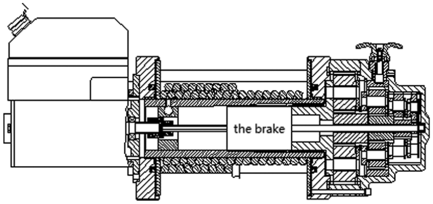
Structure diagram of the winch.
The brake mechanism of embedded-type vehicle winch is disk-type design, as shown in Figure 2. Figure 2 shows the structure diagram of common disk brake mechanism. The motor transfers kinetic energy through the coupling to the cam 2, the lug of the cam 2 coincides with the lug of the internal thread pressure plate 4, and the internal thread pressure plate through the thread pushes the torsion spring 3 to the left. The internal thread pressure plate 4 will no longer squeeze the friction plate and brake is released. Power can be passed to the next unit normally and the winch operates normally. When power is off, the motor stops rotating and the torsion spring 3 pushes the internal thread pressure plate 4 to the right. Under the action of resistance, the internal thread pressure plate 4 presses the friction disk assembly 5 and the internal friction disk 9. The friction disk assembly 5 is connected to the roller by spline, and the internal friction disk 9 is connected with the brake shaft by keyway. The internal thread pressure plate 4 presses the friction disk assembly 5 and the internal friction disk 9 and the brake works. The brake force is stronger when the load is larger.7,8

Structure diagram of common disk brake mechanism.
The reliability of disk brake is very unstable. Under the normal operation of the winch, roller will produce large amounts of heat, which cause the temperature of roller to increase sharply. Eventually, it will burn out the traction nylon rope and cause serious friction wearing, which will affect the whole life of the winch. In addition, there is a hidden trouble in the safety of the operator and the vehicle. 9
The design of the cone brake structure
As shown in Figure 3, it is the structure diagram of cone brake, which is mainly consisting of brake shaft, cam, internal friction disk, spline hub brake and single-row tapered roller bearing. The motor passes kinetic energy to the brake, making the lug of the cam 3 coincides with the lug of the internal thread brake cone 5, and the internal thread brake cone 5 moves to the left through the thread on the brake axle 1. The internal thread brake cone 5 separates from the spline hub brake 6, brake is released, power released by the brake passes to the reducer and drives the drum, and then the winch operates normally. When power is off, the motor stops rotating and the torsion spring 4 pushes the internal thread brake cone 5 to the right. Under the action of resistance, the internal thread brake cone 5 presses the spline hub brake 6. The spline hub brake 6 connects with the roller by the spline, and the internal thread brake cone 5 connects with the brake shaft. The internal thread brake cone 5 presses the spline hub brake 6 and brake works. The brake force is stronger when the load is larger.

Structure diagram of cone brake structure.
Theoretical analysis of braking performance
Loads on the brake shaft generate axial pressure F which is produced by the load couple acting on the screw mechanism and distributed in the contact surface. The screw mechanism is composed of a brake shaft with thread, a connecting piece cam, and internal thread brake cone. The load couple is forced on the cam and the internal thread brake cone and passes axial pressure through thread. As shown in Figure 4, which is the force diagram of thread (the vertical direction of the Figure 4 represents the axial direction and the horizontal direction represents the radial direction). The load force acts on the thread through the reducer, the load forced on the thread is F1, and the transmission ratio of the reducer is 1/32. The angle of thread is α (0 < α < 90°), and F4 is the axial pressure F, which is given as follows


Force diagram of thread.
The friction coefficient between materials is µ. A circle of radius 3 is established in the system of polar coordinates, R = 3 cm, and R1 = 1 cm.
Stress

The micro-area dA is given as follows
The micro-friction

The micro-torque produced by the micro-friction forcing on the axis is

The braking torque generated by one friction surface T is given as follows

The total braking torque generated by four friction surfaces is Tdisk, which is given as follows

Contacting surface of conical brake is a cone. The same infinitesimal method is used to figure out the braking torque. The model cone angle β is established in the three-dimensional cylindrical coordinate system,
The micro-area is dA, which is given as follows


The micro-friction is

The braking torque generated by the friction surface is T

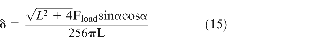

According to formulae (3)–(9), when the load is 60,000 N, the friction coefficient is 0.3. The relationship between T and the angle of the screw is shown in Figure 5.
The relationship between T and the angle of the screw.
The brake torque of disk-type brake is related to working load, friction coefficient, and the angle of the screw. The brake torque of the cone-type brake is not only related to the above factors, but also to the cone length L. In Figure 5, it shows that when the angle of the screw is 45°, the brake torque is the largest, supposing the friction coefficient is 0.3.
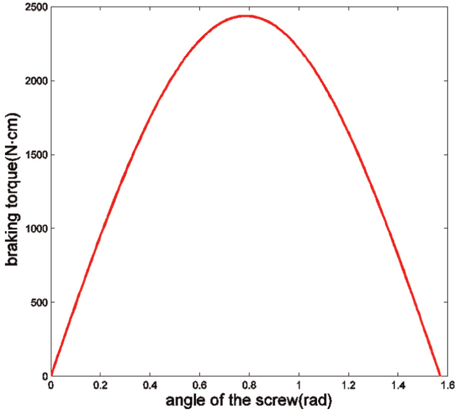
According to formulae (3)–(16), when the load changes, the relationship between the brake torque and the height of the cone is shown in Figure 6. The brake torque increases with the height of the cone and the brake force is stronger when the load is larger.
The relationship between the brake torque and the height of the cone.
Experimental analysis
In order to compare the performance of the two types of brakes, two brake mechanisms are manufactured and arranged in the same winch to conduct the experimental performance comparison. The angle 45° and the cone 6 cm are chosen.
Figure 7 is the winch test platform, whose function is to test the dynamic-load performance of winch. I am provided with two 12,000-pound winches with a disk-type and a cone-type brake mechanism, respectively. They are installed on the test platform to test no-load characteristics and dynamic-load characteristics.
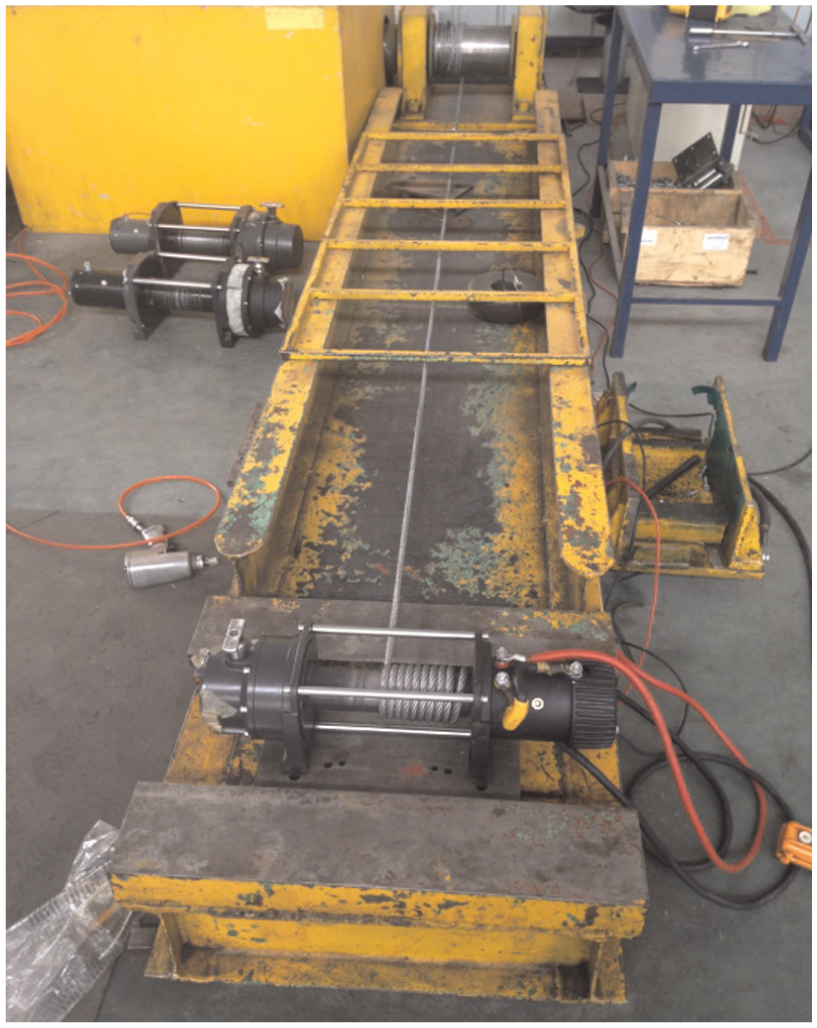
Winch test platform.
First, in the no-load test, two winches operate in the same condition without winch ropes. The brake temperature and current changes are recorded at every interval of 1 min.
Second, in the dynamic-load test, winding rope to the two winch and loading gives a different dynamic load and records dynamic load, the voltage, and current value. According to the recorded data of the no-load test, Figure 8 shows the relation curve of the temperature of two brakes which changes with time, Figure 9 shows the no-load speed of the two winches which change with time, and Figure 10 shows the changes in working currents.

The relationship between temperature of brake and time.
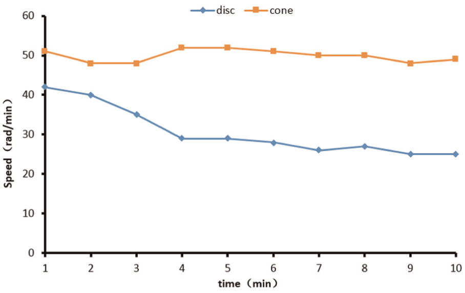
The relationship between no-load speed and time.

The relationship between working current and time.
According to Figure 8, the temperature of the winch with cone brake finally maintains at about 60°C, which is 33% lower than the 90°C of the disk brake. The cone brake has an obvious advantage in the no-load temperature. The temperature had an acute rise when the disk brake works after 3 min during the on-load test, while the cone brake temperature increases gently. From Figure 9, it can be seen that the speed of disk brake winch suddenly declines within 4 min, while the speed of winch equipped with cone brake stays at 50 rad/min. It is obvious that the cone brake has less influence on the no-load speed of winch.
The no-load current is the key to judging the performance of a winch. As shown in Figure 10, the no-load current of the cone brake winch is under 60 A, while in the disk brake winch it is over 90 A after 7 min, which consumes 33% energy than cone brake. Figure 11 shows the relationship between the working current and the load according to the recorded data of the dynamic-load test.

The relationship between working current and load.
From Figure 11, it can be seen that operating current in cone brake is always lower than that in disk brake. The efficiency of the cone-type brake is higher than that of the disk brake. T had no excess friction during the normal working condition of the winch, so there is no need to overcome the friction and the energy loss can be reduced. The cone brake does not produce excess heat and improves the performance of the winch.
Conclusion
Theoretical calculation and experimental results show that the performance of cone brake is better than the disk brake. The cone brake can reduce the occurrence of harmful friction and enhance the efficiency of winch and is able to solve the winch safety problem caused by nylon cable damage because of heat accumulation. The brake force transmission efficiency is the highest when the angle of the screw on the brake shaft is 45°. The disk brake cannot be fully released when the winch works normally. There is large amount of heat generated during the high-speed rotation of the principal axes. Heat accumulates inside the roller and cannot be evacuated. The temperature of the roller rises drastically and would burn nylon rope around the drum in the end. And the friction between the brake disk and the spindle will also reduce the service life of the main shaft. The cone brake can solve the problem, hence the winch performance can be improved significantly.
Footnotes
Academic Editor: Francesco Massi
Declaration of conflicting interests
The author(s) declared no potential conflicts of interest with respect to the research, authorship, and/or publication of this article.
Funding
The author(s) disclosed receipt of the following financial support for the research, authorship, and/or publication of this article: This work was financially supported by the National Natural Science Foundation of Chain (51305177) and the Natural Science Foundation of Jiangsu Province of China (BK20130229).